ISSN: 2278-3075, Volume-9 Issue-2, December 2019
Abstract: The article deals with solid rotor asynchronous electric machine mathematical model. It is substantiated that the use of generalized electrical machine theory for building the mathematical model is rational at the design stage to analyze the electromagnetic and electromechanical processes in an electric machine and a power converter. The mathematical model with some circuits on the rotor was considered to account for the effect of current displacement in a solid rotor. We used the field theory to determine the number of circuits. For this purpose, the calculations series of the magnetic field distribution in the active part of the electric machine when the rotor is stationary (in short circuit mode) and the stator winding are powered by different frequencies currents were carried out. The modeling of a high-speed electric generator with a solid asynchronous rotor was carried out. Its power is 100kW and its rotational speed is 100 000 rpm. The analysis of the high-speed generator parameter approximation showed that the use of three circuits in the equivalent circuit is rational to account for the effect of current displacement in a solid rotor. The mathematical model results when connecting a rotating high-speed electric generator to a voltage source are showed. The assessment of the current displacement effect in a solid rotor was examined twice: with one circuit in a rotor chain and with three circuits in it. Comparison of the electromagnetic processes modeling results showed that the use of three circuits model provides the more accurate representation of electromagnetic processes in the solid rotor asynchronous electric machine. The modeling results significantly differs during transients when using the one-circuit model. In the steady state, the stator current fundamental harmonics and the average value of electromagnetic moment are the same for both models.
Keywords: asynchronous electric machine, mathematical modeling, solid asynchronous rotor, high-speed electric generator.
I. INTRODUCTION
T
he use of a gas power plants is one of the future-oriented area of energy systems development. The use of 50 – 250 kW power plants as a part of distributed generation energy systems and autonomous power supply systems is relevant [1 - 3]. In this power range, the gas micro-turbine high rates operation is possible only when the rotational speed is above 50 000 rpm. The use of gearboxes inRevised Manuscript Received on December 05, 2019.
Pavel Grigorievich Kolpakhchyan, Power Engineering Department, Rostov State Transport University (RSTU), Rostov-on-Don, Russia.
Alexey Rifkatovich Shaikhiev,Power Engineering Department, Rostov State Transport University (RSTU), Rostov-on-Don, Russia.
Alexander Evgenievich Kochin, Power Engineering Department, Rostov State Transport University (RSTU), Rostov-on-Don, Russia.
Margarita Sergeevna Podbereznaya, Power Engineering Department, Rostov State Transport University (RSTU), Rostov-on-Don, Russia.
such systems reduces the energy complex performance and leads to inefficiency of the gas micro-turbines use. In this case the electric generator must be a high-speed electric machine placed on a common shaft with a turbine [4].
Different commutatorless electric machines can be used as high-speed electric generators for gas micro-turbines. The permanent magnet synchronous electric machines have the best specific indicators [5]. However, the problems of ensuring the permanent magnets strength limit the power of the generator depending the rotational speed [6,7]. The refusing to place permanent magnets on the rotor and the use of solid asynchronous rotor can allow overcoming this limitation [8-10].
The analysis of electromagnetic and electromechanical processes in the electric machine and power converter are necessary when developing a solid asynchronous rotor high-speed electric generator. The design stage focuses on the following tasks: selection of rational geometric ratios of an electromechanical converter, defining the effective control methods and control system settings. The use of high-speed asynchronous electric machine mathematical model allows us to deal with these tasks. There for the developing of solid rotor asynchronous electric machine is a current challenge.
II. PROPOSEDMEHODOLOGY
A. Problem Statement
The asynchronous rotor high-speed electric generator was developed by the authors within the agreement of the Ministry of Education and Science of the Russian Federation (unique identity code is RFMEFI60417X0174) [2, 4, 8]. The solid asynchronous rotor high-speed electric machine mathematical model was designed to address the challenges above.
The use of field theory provide the greatest accuracy of the electric machine model. However, the application of this approach to the modeling of electromagnetic processes requires considerable computational time. For the analysis of electromagnetic and electromechanical processes in electrical machines working in conjunction with a power semiconductor power converter, the using the theory of a generalized electric machine is rational [11-14].
The investigated high-speed electric generator is an electric alternating current machine with a solid rotor. The stator winding was five-phase one to improve the harmonic field, magnetic field in the gap and reduce the current in a power semiconductor devices of an electric power converter. The stator has a groove design
with magnetic wedges on the side of the gap. The number of
Mathematical Model of a Solid Rotor
Asyncronous Electric Machine
pole pairs is one. The stator winding is two-layer, simple circuit one. The rotor diameter is 45 mm, the outer diameter of the stator is 110 mm, the air gap is 0.35 mm. The solid rotor in the electric machine under consideration makes it impossible to use the standard mathematical models.
The asynchronous solid rotor high-speed electric generator mathematical model is based on the model of a generalized electric machine.
The main assumptions adopted in this model are as follows:
only the fundamental harmonic of the magnetic field in the gap is taken into account;
two orthogonally centered windings replace the distributed, multiphase stator winding;
saturation of the magnetic system is taken into account by the fundamental harmonic of the magnetic field in the gap; several pairs of diametrical orthogonal concentrated windings replace the solid asynchronous rotor.
The mathematical model parameters determination the theory of magnetic circuits, does not allow us to achieve the necessary accuracy in the case of a solid rotor electric machine. Therefore, the number of winding systems and the parameters of a high-speed electric machine must be determined using the magnetic field calculating methods.
To determine the structure and parameters of the asynchronous solid rotor high-speed electric machine mathematical model we used the approaches, described in [15] and developed in [16-18].
For this, a series of calculations of the distribution of the magnetic field in the active region of the studied electric machine is carried out with the rotor stationary (in the short-circuit mode) and the stator winding is powered by currents with different frequencies. For this purpose, a calculations series of the magnetic field distribution in the active part of the studied electric machine is carried out with the rotor stationary (in the short-circuit mode) and the stator winding is powered by different frequencies currents.
We determined the equivalent circuit parameters of asynchronous electric machine by using the least square method. The imaginary part of stator phase inductance versus the stator current frequency is calculated using the field theory and approximated. The method was modified taking into account the strong influence of the current displacement effect in a solid rotor. At the first stage, we used the simplified equivalent circuit of the one circuit asynchronous electric machine. At the second stage, there were two circuits on the rotor and the values obtained at the first stage were used as the initial approximation of the approximated parameters. With insufficient accuracy of the approximation, one or more stages of calculations must be performed with an increase in the number of circuits on the rotor.
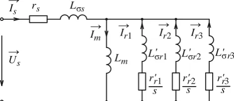
To calculate the distribution of the magnetic field, the FEMM v.4.2 (© David Meeker) software was used ) [19]. For modeling processes in solid asynchronous rotor high-speed generator it is necessary to use three winding rotor systems. In this case, the equivalent circuit of a high-speed asynchronous electric machine has the form as Figure 1 shows, where:
𝑈 𝑠, 𝐼 𝑠are the voltage and stator current;
𝐼 𝑚, 𝐼 1, 𝐼 2,… ,
𝐼 𝑛is the magnetization circuit current and rotor circuit currents;
𝑟𝑠, 𝐿𝜎𝑠 are resistance and stator inductance;
𝐿𝑚 is the magnetization inductance;
𝑟′
𝑟1, 𝐿′𝜎𝑟 1 ; 𝑟′𝑟2 , 𝐿′𝜎𝑟 2; …; 𝑟′𝑟𝑛 , 𝐿′𝜎𝑟𝑛 are active resistances and inductances of the rotor circuits scattering;
𝑠 =𝜔𝑠−𝑝𝜔
𝜔𝑠 is the relative slip;
p is the number of the stator winding poles pairs;
[image:2.595.316.552.194.296.2]ωs, ω are the stator current frequency and rotor angular rotational speed.
Fig. 1: Equivalent circuit of a high-speed electric machine
As a result of calculations, the following equivalent circuit parameters were obtained:
Lm = 0,001405 H is the magnetization inductance Lσs = 0.00003852 is the stator leakage inductance; rs = 0.0715 Ohm is the stator resistance;
L´σr1= 0.00005370 H is the scattering inductance of the
first rotor circuit
r´r1= 0.02201 Ohm is the resistance of the first rotor circuit L´σr2= 0.00014345 H is the is the scattering inductance of
the second rotor circuit
r´r2= 0.10385 Ohm is the resistance of the second rotor
circuit
L´σr3= 0.00015468 Гн is the scattering inductance of the
third rotor circuit
r´r3= 1.5514 Ohm is the resistance of the third rotor circuit
III. RESULTSANDDISCUSSION
A. Equations of A Mathematical Model of A Solid Rotor Asynchronous Electric Machine
The analysis of electromagnetic processes in a power converter is one of the tasks to solve using a mathematical model. It is more convenient to write equations in the coordinate system α – β, which is stationary relative to the stator. In accordance with the equivalent circuit of a high-speed asynchronous electric machine the equations of electric balance for the rotor and stator circuits are as follows:
𝑈 𝑠= 𝑟𝑠𝐼 𝑠+ 𝑑 𝑑𝑡𝛹 𝑠;
0 = 𝑟′
𝑟1𝐼 𝑟1− 𝑗𝑝𝜔𝛹 𝑟1+ 𝑑
𝑑𝑡𝛹 𝑟1;
0 = 𝑟′
𝑟2𝐼 𝑟2− 𝑗𝑝𝜔𝛹 𝑟2+ 𝑑
𝑑𝑡𝛹 𝑟2;
0 = 𝑟′
𝑟3𝐼 𝑟3− 𝑗𝑝𝜔𝛹 𝑟3+ 𝑑 𝑑𝑡𝛹 𝑟3,
, (1)
where 𝑈 𝑠 is the stator voltage vector;
𝛹 𝑠, 𝛹 𝑟1, 𝛹 𝑟2, 𝛹 𝑟3 are the stator flux link vector and rotor circuits;
𝐼 𝑠, 𝐼 𝑟1, 𝐼 𝑟2, 𝐼 𝑟3 are the vector
r
sL
σsU
sI
sI
mI
r1→
I
r2I
r3L
mL
σr1'
L
σr2'
L
σr3'
r
r1'
r
r2'
r
r3'
s
s
s
→
→
→
→
ISSN: 2278-3075, Volume-9 Issue-2, December 2019
of stator currents and rotor circuits;
𝜔 is the angular rotational speed.
The flux linkages and the stator and rotor circuits currents are connected by the following relations:
𝛹 𝑠 = 𝐿𝜎𝑠𝐼 𝑠+ 𝐿𝑚𝐼 𝑚; 𝛹 𝑟1 = 𝐿′𝜎𝑟 1𝐼 𝑟1+ 𝐿𝑚𝐼 𝑚;
𝛹 𝑟2= 𝐿′
𝜎𝑟 2𝐼 𝑟2+ 𝐿𝑚𝐼 𝑚; 𝛹 𝑟3 = 𝐿′𝜎𝑟 3𝐼 𝑟3+ 𝐿𝑚𝐼 𝑚; (2)
𝐼 𝑚 = 𝐼 𝑠+ 𝐼 𝑟1+ 𝐼 𝑟2+ 𝐼 𝑟3.
Taking into account several rotor circuits in the high-speed electric machine equivalent circuit, it is advisable to calculate the electromagnetic moment through the flux linkage and stator current:
𝑀𝑒𝑚 = 𝑚
2 𝛹 𝑠× 𝐼 𝑠 , (3) Wher m is the number of stator winding phases.
To solve equations (1) by numerical methods with consideration to (2), they must be converted to the Cauchy form. The performing of such transformations is analytically difficult when there are more than on rotor circuit in the equivalent circuit. Therefore, the transformations of the right-hand sides of differential equations describing electromagnetic processes in a high-speed electric machine must be performed numerically, at every step of the modeling.
In the equations (1), the integration variables are the projections of the stator flux linkages and the rotor circuits on the α - β axis. To bring this system of equations to the Cauchy form, it is necessary to determine the stator and rotor circuit currents through the flux linkages values. For this purpose, it is necessary to solve a system of linear equations obtained from correlation (2).
The system of equations connecting flux linkages and circuit currents in matrix form is as follows:
[𝛹] = [𝐿][𝐼],
where [𝛹], [𝐼] are the vector projections of flux linkages and stator currents and rotor circuits on the α - β axis.
[𝐿] is the inductance matrix.
The system of differential equations describing electromagnetic processes in a high-speed asynchronous electric machine is given below. The equations are reduced to the Cauchy form and are written in matrix form with respect to the projections of the stator flux linkages and the rotor circuits on the α - β axis.
U L
R D p dt
d 1
, (3) wher [𝑅] is the diagonal matrix of windings active resistances;
[𝑈] is the vector of the voltages applied to the windings. The [D] matrix takes into account the rotation EMF and is as follows:
[𝐷] =
[𝐷𝑠] 0
[𝐷𝑟]
[𝐷𝑟]
0 [𝐷𝑟]
.
where [𝐷𝑠] = 0 00 0 and [𝐷𝑟] = −10 10 are matrices
describing the stator and rotor windings rotation.
The conversion of phase voltages and currents values in their projection on the α - β axis which is fixed relative to the stator and in reverse order are made using the Klark’s forward and reverse transformations for the case of a five-phase electric machine:
𝑋𝛼
𝑋𝛽 = 2 5
1 cos2𝜋
5 cos 4𝜋
5 cos 6𝜋
5 cos 8𝜋
5
0 sin2𝜋
5 sin 4𝜋
5 sin 6𝜋
5 sin 8𝜋
5
⋅ 𝑋𝐴
𝑋𝐵
𝑋𝐶
𝑋𝐷
𝑋𝐸 ;
𝑋𝐴
𝑋𝐵
𝑋𝐶
𝑋𝐷
𝑋𝐸
=
1 0
cos2𝜋
5 sin 2𝜋
5
cos4𝜋
5 sin 4𝜋
5
cos6𝜋
5 sin 6𝜋
5
cos8𝜋
5 sin 8𝜋
5
⋅ 𝑋𝑋𝛼
𝛽 ,
where X is the convertible value.
The equations system (3) is solved by numerical Cauchy methods. In this form, the equations system (3) can be used to create a high-speed electric machine model in such software systems like MatLAB Simulink. This allows you to use this mathematical model for the analysis of electromagnetic and electromechanical processes as part of complex models of the studied objects.
B. Modeling A Solid Asynchronous Rotor High-Speed Electric Generator
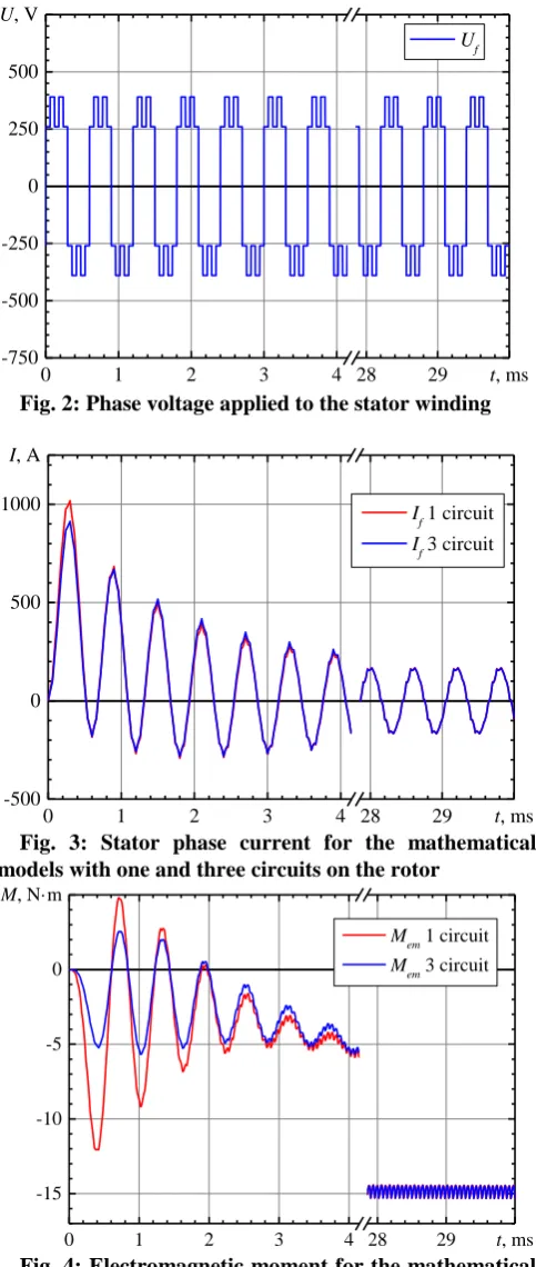
The processes modeling in a solid asynchronous rotor high-speed electric generator was performed as an example of using the considered model. The connection of a rotating electric machine to a voltage source in generator mode was considered. The voltage generated by the electric power converter is applied to the stator winding. The single-pulse modulation is used, the voltage at the input of the converter (in the DC link) is 650 V. The rotational speed of the generator is taken equal to 1666.7 Hz (100,000 rpm), the frequency of the voltage applied to the stator winding is less than 12 Hz, which corresponds to the absolute slip value in the nominal mode.
To assess the effect of current displacement on processes in a high-speed asynchronous electric machine, we studied the use of one and three rotor circuits in the equivalent circuit. The parameters of the rotor circuit in the equivalent single-circuit are adopted on the basis of the equality of the equivalent complex resistance of the rotor chain in models with one and three circuits when the slip is nominal.
The implicit one-step methods show better results in the case when the impulse voltage is applied to the stator windings when solving the equations of the considered mathematical model (3). Therefore, the solution was carried out by the second-order Adams-Moulton method. The simulation step was taken equal to 1 μs.
Fig. 2: Phase voltage applied to the stator winding
Fig. 3: Stator phase current for the mathematical models with one and three circuits on the rotor
Fig. 4: Electromagnetic moment for the mathematical models with one and three circuits on the rotor
IV. ANALYSISOFTHERESULTS
The modeling results show that the use of a mathematical model with three circuits on the rotor provides a more accurate representation of electromagnetic processes in a solid rotor asynchronous electric machine. The difference in simulation results is especially noticed during transients. The maximum difference in currents is 10-15%, and the moments differ by 2.5 times. The value of the fundamental harmonic of the stator current and the average value of the electromagnetic moment for both models coincide. The divergence up to 5% has the swing range and the maximum
values of the phase current.
Also, other modes of operation of a high-speed asynchronous electric generator was simulated. The direct start, power converter supply with various output voltage generating methods and variable load of the electric generator was simulated.
The study results show that the developed mathematical model sufficiently represents electromagnetic processes in the solid rotor high-speed electric machine. Its use allows you to analyze processes with sufficient accuracy and solve tasks.
V. CONCLUSIONS
1. In the design of the solid rotor high-speed electric generator, there is the need for analysis of electromagnetic and electromechanical processes in the electric machine and power converter. For this purpose, the application of the asynchronous electric machine mathematical model based on the theory of a generalized electric machine is rational.
2. The application of a mathematical model with several rotor circuits is necessary to take into account the current displacement effect in the solid rotor.
3. The use of calculations series of the magnetic field distribution in the active part of the electric machine when the rotor is stationary (in short circuit mode) and the stator winding are powered by different frequencies currents is advisable to determine the structure and parameters of a mathematical model of the solid rotor high-speed generator. 4. The use of three circuits in the asynchronous electric machine equivalent circuit is necessary to take into account the effect of current displacement in a solid asynchronous rotor.
5. The use of implicit one-step methods, for example, the second-order Adams-Moulton method is rational to solve the differential equations system for modeling the high-speed asynchronous electric machine.
6. The use of a mathematical model with three circuits on the rotor provides a more accurate representation of electromagnetic processes in a solid rotor asynchronous electric machine. The difference in simulation results is especially noticed during transients. The value of the fundamental harmonic of the stator current and the average value of the electromagnetic moment for both models coincide.
ACKNOWLEDGMENT
The research was carried out within the agreement (them “Scientific and technical solutions to develop the efficient high speed generator equipment for micro gas-turbine unit” № 14.604.21.0174, 26 September 2017) by order the Ministry of Education and Science of the Russian Federation, Federal Target Program “Development of the focal areas for the development the scientific and technical complex of Russia for 2014-2020”. The unique ID for applied research (project) is RFMEFI60417X0174.
0 1 2 3 4 28 29 t, ms
-750 -500 -250 0 250 500
U, V
Uf
0 1 2 3 4 28 29 t, ms
-500 0 500 1000
I, A
If 1 circuit
If 3 circuit
0 1 2 3 4 28 29 t, ms
-15 -10 -5 0
M, N·m
Mem 1 circuit
ISSN: 2278-3075, Volume-9 Issue-2, December 2019
REFERENCES
1. A. Ahmad, Smart Grid as a Solution for Renewable and Efficient Energy. Advances in Environmental Engineering and Green
Technologies. IGI Global, 2016.
https://books.google.ru/books?id=c6EoDAAAQBAJ.
2. P.G. Kolpakhchyan, A.R. Shaikhiev, B.M. Goltsman, A.S. Oshchepkov, “Local Intelligent Energy Systems Based on Gas Microturbines with High-Speed Electric Generators”, International Journal of Mechanical Engineering and Technology, vol. 9, 2018, pp. 51–57.
3. A. Duffy, M. Rogers, L. Ayompe, Renewable Energy and Energy Efficiency: Assessment of Projects and Policies, John Wiley & Sons, 2015.
4. P.G. Kolpakhchyan, V.I. Parshukov, A.R. Shaikhiev, A.E. Kochin, M.S. Podbereznaya, “High Speed Generator for Gas Microturbine Installations.” International Journal of Applied Engineering Research, vol. 12 (23), 2017, pp. 13874–13878.
5. D. T. McGuiness, M. O. Gulbahce, D. A. Kocabas, “A Performance Comparison of Different Rotor Types for High-Speed Induction Motors”, In 2015 9th International Conference on Electrical and Electronics Engineering (ELECO), 2015, pp. 584–589.
6. J.H. Ahn, K.H. Cheol, K. Chang-woo, Ch. Jang-young, “Rotor Design of High-Speed Permanent Magnet Synchronous Motors Considering Rotor Magnet and Sleeve Materials”, IEEE Transactions on Applied Superconductivity, vol. 28, 2018, pp. 1–4.
7. P.G. Kolpakhchyan, B.N. Lobov, A.P. Mikitinskiy, I.V. Rusakevich, “The Production Possibility of Permanent Magnet High Speed Electric Generator Rotors”, 2018 10th International Conference on Electrical Power Drive Systems, ICEPDS 2018 - Conference Proceedings, 2018. 8. P.G. Kolpakhchyan, V.I. Parshukov, A.R. Shaikhiev, A.E. Kochin, M.S. Podbereznaya, “High Speed Generator for Gas Microturbine Installations”, International Journal of Applied Engineering Research, vol. 12 (23), 2017, pp. 13874–13878.
9. L. Papini, C. Gerada, D. Gerada, A. Mebarki, “High Speed Solid Rotor Induction Machine: Analysis and Performances”, In 2014 17th International Conference on Electrical Machines and Systems (ICEMS), 2014, pp. 2759–2765.
10. J. Pyrhönen, J. Nerg, P. Kurronen, U.Lauber, “High-Speed High-Output Solid-Rotor Induction-Motor Technology for Gas Compression”, Industrial Electronics, IEEE Transactions on, vol. 57, 2010, pp. 272–280.
11. E. Levi, “General Method of Magnetising Flux Saturation Modelling in D-Q Axis Models of Double-Cage Induction Machines”, IEE Proceedings - Electric Power Applications, vol. 144 (2), 1997, pp. 101–109. doi:10.1049/ip-epa:19970781.
12. T. Ahfock, A. Hewitt. “Modeling of the Solid Rotor Induction Motor,” In: AUPEC 2005: 15th Australasian Universities Power Engineering Conference, 25-28 Sep 2005, Hobart, Australia.
13. J. Pedra, I. Candela, L. Sainz, “Modelling of Squirrel-Cage Induction Motors for Electromagnetic Transient Programs”, IET Electric Power Applications, vol. 3 (2), 2009, pp. 111–122.
14. Y. Hu, Ch. Jinzhe, D. Xiying, “Analysis and Computation on Magnetic Field of Solid Rotor Induction Motor”, IEEE Transactions on Applied Superconductivity, vol. 20 (3), 2010, pp. 1844–1847.
15. S. Williamson, M.J. Robinson, “Calculation of Cage Induction Motor Equivalent Circuit Parameters Using Finite Elements”, IEE Proceedings B Electric Power Applications, vol. 138 (5), 1991, p. 264. 16. D. Dolinar, R. De Weerdt, R. Belmans, E. M. Freeman, “Calculation of
Two-Axis Induction Motor Model Parameters Using Finite Elements”, IEEE Transactions on Energy Conversion, vol. 12 (2), 1997, pp. 133–142.
17. E. Levi, “General Method of Magnetising Flux Saturation Modelling in D-Q Axis Models of Double-Cage Induction Machines”, IEE Proceedings - Electric Power Applications, vol. 144 (2), 1997, pp. 101–109.
18. V. Wilow, “Electromagnetical Model of an Induction Motor in COMSOL Multiphysics”, EES Examensarbete / Master Thesis. KTH, Electrical Energy Conversion, 2014.
19. D. Meeker, Finite Element Method Magnetics. Version 4.2. User's
Manual, 2018. Available: