iii
UNIVERSITI TEKNIKAL MALAYSIA MELAKA
DEVELOPMENT OF HAND GESTURE ROBOT USING Xbee
COMMUNICATION
This report is submitted in accordance with the requirement of the Universiti Teknikal Malaysia Melaka (UTeM) for the Bachelor of Electrical Engineering Technology
(Industrial Automation and Robotics) with Honours
by
MOHD FAIZ BIN HAT
B071210375
910209-06-5677
iv
DECLARATION
I hereby, declared this report entitled “DEVELOPMENT OF HAND GESTURE MOBILE ROBOT USING Xbee COMMUNICATION” is the results of my own research except as cited in references.
Signature :……….. Name :MOHD FAIZ BIN HAT
v
APPROVAL
This report is submitted to the Faculty of Engineering Technology of UTeM as a partial fulfillment of the requirements for the of Electrical Engineering Technology (Industrial Automation and Robotics) with Honours. The member of the supervisory is as follow:
vi
DEDICATION
vii
ACKNOWLEDGEMENT
First of all, I would like to express my deepest gratitude to my supervisor, Mr.Mohd Zaidi Bin Mohd Tumari, for accept and giving me this wonderful and yet interesting final year project. His supervision both aided me to channel and specify the discussed ideas and at the same time provided much appreciated freedom and support to explore new concepts. However, his endless drives for new and better results is highly appreciated, instead of willing to share his own experience and spend his free time to supervise me throughout the implementation of this project.
My appreciation also goes to my parents who bore immense difficulties to educate their children at the highest level. Their affection and love has brought happiness and joy to my life and therefore made this task becomes much easier to be implemented.
viii
ABSTRACT
ix
ABSTRAK
x
TABLE OF CONTENT
DECLARATION ... iii
APPROVAL ... iv
DEDICATION ... v
ACKNOELEDGEMENT ... vi
ABSTRACT ... vii
ABSTRAK ... viii
TABLE OF CONTENT ... ix-x LIST OF TABLE ... xi
LIST OF FIGURE ... xii
LIST OF SYMBOLS AND ABBREVIATIONS ... xiii
CHAPTER 1... 1
1.1 Project Background ... 1
1.2 Problem statement ... 2
1.3 Scope ... 2
1.4 Objectives ... 2
CHAPTER 2... 3
2.1 Introduction ... 3
2.2 Previous Project Work ... 4
2.2.1 Hand Gesture Robot Movement ... 4
2.2.2 Algorithm ... 5
2.2.3 Glove Controller ... 6
2.2.4 Finger Binary System ... 7
2.2.5 Hand Gesture recognition, Wireless vision, Mobile robot, Color spaces, Skin Detection ... 8
2.2.6 XBee, Arduino, Wireless Sensor Networks ... 8
2.3 Hand Gesture Recognition System For Traffic Light Control (TLC) ... 9
xi
2.4 SIMULATIONS ... 11
CHAPTER 3... 13
3.1 INTRODUCTION ... 13
3.2 Work flow of project. ... 14
3.3 Electrical Hardware Review ... 15
3.4 ARDUINO UNO ... 15
3.5 Xbee Module ... 17
3.6 Xbee Shield ... 18
3.7 Flex Sensor ... 19
3.8 DC Motor... 20
3.9 Motor Driver ... 21
3.10 Design of hand gesture robot ... 22
3.11 Mechanism System Design ... 23
3.12 Circuit System ... 24
3.13 Arduino Software ... 26
3.14 CoolTerm Software ... 26
3.15 Proteus ... 27
CHAPTER 4... 30
4.1 Introduction ... 30
4.2 Flex Sensor Control ... 30
4.3 Robot Movement ... 32
4.4 Robot Communication... 33
CHAPTER 5... 36
5.1 Introduction ... 38
5.2 Conclusion ... 38
xi
LIST OF FIGURES
Figure 2.1: Block diagram for the proposed system ... 4
Figure 2.2: Creation of Makeshift Flex Sensors ... 7
Figure 2.3: Experimental Sensor Network ... 9
Figure 2.4: Diagram Of Hand Gesture Recognition System For TLC ... 10
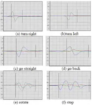
Figure 2.5: The resulting test template sequence for each hand gesture ... 12
Figure 3.1: Hand Gesture Robot Block Diagram ... 13
Figure 3.2: Flow Chart ... 14
Figure 3.3: Arduino Uno Kit ATmega 328 ... 16
Figure 3.4: Xbee Modul S1 ... 17
Figure 3.5: Xbee Shield for Arduino... 18
Figure 3.6: Flex Sensor 2.2” ... 20
Figure 3.7: DC Motor ... 21
Figure 3.8: Motor Driver ... 22
Figure 3.9: Design Hand Gesture Robot ... 23
Figure 3.10: Base Robot Design ... 23
Figure 3.11: Robot Full Mechanical Design ... 23
Figure 3.11: Hand Gesture Circuit On the Glove ... 25
Figure 3.12: Motor Control Circuit ... 29
Figure 3.13: Coding Of Flex Sensor To Arduino ... 29
Figure 3.14: Coding Of Motor Control To Arduino ... 27
Figure 3.15: Xbee Configure Using CoolTerm... 29
Figure 3.16: Proteus simulation software ... 29
Figure 3.17: Motor driver simulation circuit ... 29
Figure 4.1: Robot Climb At 80º ... 33
Figure 4.2:Hand Gesture Robot At 90 Meter ... 35
Figure 4.3: Range Of Xbee Connect And Disconnect ... 35
Figure 4.4: Distance Vs Signal Frequency ... 36
xii
LIST OF TABLE
Table 2.1: Code Generation For Corresponding Gestures ... 5
Table 2.2: Operation In Algorithmic Form ... 6
Table 2.3: Specification DC Motor ... 21
Table 2.4: Value of resistance with bend ... 31
Table 2.5: Motor movement position ... 32
Table 2.6: Observations Range Xbee In Outdoor Conditions (Outdoor Area) ... 36
xiii
1
CHAPTER 1
INTRODUCTION
1.1 Project Background
Robot's are becoming one of the major development in field of technology and robotics are being used in many fields like defense, automobile, medical, construction etc. They are also being used to help people in form of fire fighting robots. Today, the good of project robotics on topic is "Hand gesture mobile robot using Xbee Communication". The main objective of this project work is to control a robot with gestures of our hand. This project is based on 2 major component Arduino microcontroller and Xbee which are discussed in this project report.
2
1.2 Problem statement
This project is designed to have a stable shape to move on various surfaces. Hand Gesture robot (Chain wheel motion) helps to overcome difficult terrain like bumpy, slope, stony etc very easily. This type of vehicle can traverse places which are not in reach of regular wheel mechanisms. Here a simple tanker like vehicle motion. This model is remote controlled thru a set of hand gesture.
1.3 Scope
In this project there will be 3 work scopes. For the first scope, it is the mechanical design. In this scope it will be the base of the robot, and wheel of robot. The second scope is the electronics design. For this scope, the arduino uno, dc motor, flex sensor, Xbee and motor driver has been use. Lastly is the software design. In this scope, the project uses the Arduino IDE and use the XBee program.
1.4 Objectives
To develop a mobile robot that able to move according to hand gesture robot
To design the physical structure, electronic circuit and control of the robot
3
CHAPTER 2
LITERATURE REVIEW
2.1 Introduction
In this chapter, base on previous study work that have been done in different field of research. There are different research such as artificial Xbee Module , data glove based, flex sensor, programming and etc. These review also emphasizes on research project in order to understand clearly regarding with develop of hand gesture robot. In this chapter, detail summaries of the hand gesture robot from previous research.
4
2.2 Previous Project Work
2.2.1 Hand Gesture Robot Movement
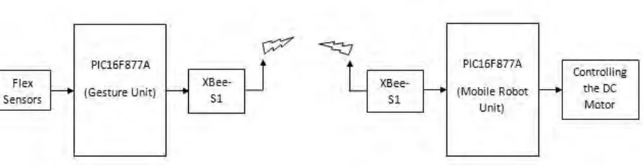
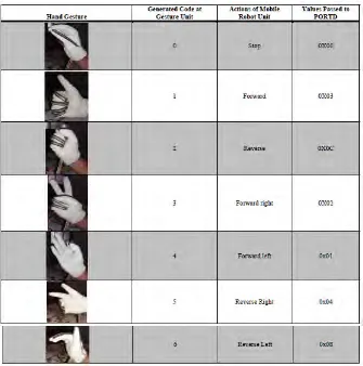
According to Rajkanna, Mathankumar (2014) the mobile robot unit gets the code signal from the module kit unit through XBee-S1. This code is a standard code. Then, the codes are getting coordinated and related to control activity is performed on DC motor driver. Table 2.1 demonstrates the different operations of the motor driver.
[image:16.612.129.587.301.420.2]
5
2.2.2 Algorithm
According to Rajkanna, Mathankumar (2014) the finger developments can be made smoother by utilizing great quality flex sensors or by utilizing more carbon containing plastics. The XBee utilized as a part of this undertaking has been confined to 100m in open air environment. By utilizing repeaters and extenders the scope of radio wire can be expanded.
[image:17.612.195.530.103.441.2]In normal mode, the result of the flex sensor is zero, at what point it suffered any pressure is the result of several created from the sensor. Voltage outputs are easily turned into a flag developed by the internal ADC module PIC microcontroller. After changing over the quality of the computerized check the controller experience any new
6
signs achieved positions or older. On the off chance the new signals identified later the controller sends a code related to their versatility robot unit via XBee-S1. Figure 2.2 show the operation was examined under the algorithms structure.
Table 2.2: Operation In Algorithmic Form Step 1: start the ADC and UART modules
Step 2: Change the flex sensor output into a computerized signs
Step 3: Compare the change in static movement
Step4: Compare the value changes with effective change If they hop along with step 2
Step 5: If another value has changed more in line with that laid down value
Step6: Repeat the process from step 2
2.2.3 Glove Controller
7
Figure 2.2: Creation of Makeshift Flex Sensors
2.2.4 Finger Binary System
8
2.2.5 Hand Gesture recognition, Wireless vision, Mobile robot, Color
spaces, Skin Detection
According to Manigandan and Jackin (2010) vision-based hand gesture recognition has programmedis a very dynamic checkpoint lately with Lively application, for example, human PC connection (HCI), robot control, and communication through gestures of understanding. That the general issue is really difficult because of the wide range of issues calculate how chaotic static element and hand signal, the basics of the complex, and barriers. Assaults simplification of the issues in which require complex calculations PC asset requires concentrated. What inspires for this work is, the issue of robot path, where the occupied by controlling the posture of the robot with signals given by man. Due to the ongoing operational requirements.
2.2.6 XBee, Arduino, Wireless Sensor Networks
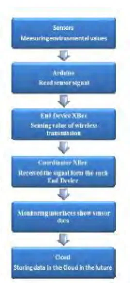
According to Sung, Chen et al. (2014) before the wireless transmission not commonplace, rely on the signal wire is passed to the microprocessor for analysis, as long as the number of over one signal cable, layout is very likely to cause problems.
9
Figure 2.3: Experimental Sensor Network
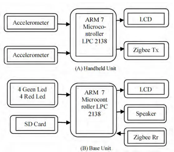
2.3 Hand Gesture Recognition System For Traffic Light Control (TLC)
2.3.1 TLC System
10
Figure 2.4: Diagram Of Hand Gesture Recognition System For TLC
11
2.4 SIMULATIONS
According to Swapnali and Chilveri (2014) in order to test the performance of the proposed hand-gesture-based interface for navigating a car-robot, it should be generate a comprehensive data base to test the interface There are several elements to make the issue hand gesture recognition became very difficult. In the beginning of the all, the diversity of the human causes the same type of hand gestures towards its own each time.
Notwithstanding to the same individuals, councils of different varieties of the same hand movements may be indistinguishable. Furthermore, the same hand movement can implemented in a variety and / or the size of its own. Third, the same hand signals can be performed in a separate speed. Along these lines, the 8 basic information was create.
12