This is a repository copy of Seismic response evaluation of non-structural drywall building components: Planning of an experimental campaign.
White Rose Research Online URL for this paper: http://eprints.whiterose.ac.uk/141874/
Version: Accepted Version
Proceedings Paper:
Fiorino, L, Iuorio, O orcid.org/0000-0003-0464-296X, Macillo, V et al. (3 more authors) (2014) Seismic response evaluation of non-structural drywall building components: Planning of an experimental campaign. In: Landolfo, R and Mazzolani, FM, (eds.) Eurosteel 2014. Eurosteel 2014: 7th European Conference on Steel and Composite Structures, 10-12 Sep 2014, Naples, Italy. ECCS European Convention for Constructional Steelwork . ISBN 978-92-9147-121-8
This is an author produced version of a paper published in Eurosteel 2014: 7th European Conference on Steel and Composite Structures.
[email protected] https://eprints.whiterose.ac.uk/ Reuse
Items deposited in White Rose Research Online are protected by copyright, with all rights reserved unless indicated otherwise. They may be downloaded and/or printed for private study, or other acts as permitted by national copyright laws. The publisher or other rights holders may allow further reproduction and re-use of the full text version. This is indicated by the licence information on the White Rose Research Online record for the item.
Takedown
If you consider content in White Rose Research Online to be in breach of UK law, please notify us by
EUROSTEEL 2014, September 10-12, 2014, Naples, Italy
SEISMIC RESPONSE EVALUATION OF NON-STRUCTURAL DRYWALL
BUILDING COMPONENTS:
Planning of an experimental campaign
Luigi Fiorino, Ornella Iuorio, Vincenzo Macillo, Maria Teresa Terracciano, Tatiana Pali, Raffaele Landolfo
University of Naples Federico II, Dept. of Structures for Engineering and Architecture, Italy [email protected], [email protected], [email protected], [email protected],
[email protected], [email protected]
INTRODUCTION
Past earthquakes have shown that the damage to non-structural elements can severely limit the functionality of most affected buildings and cause substantial economic losses. Among the non-structural building components, the ceiling-partition systems represent a large economic investment in construction sector. Nevertheless, their seismic performance is poorly understood, because information and specific guidance are very limited. In the last years, international studies have been conducted on the seismic behaviour of light gage steel stud partition walls (Lee et al. [1], Restrepo and Bersofsky [2], Tasligedik et al. [3], Retamales et al. [4], Magliulo at al. [5]), suspended ceilings (Badillo et al. [6], Magliulo et al. [7], Gilani et al. [8], Soroushian et al. [9],) and partition walls - ceiling systems (Filiatrault et al. [10], McCormick at al. [11]). Since the behaviour of these systems cannot be easily simulated with traditional structural analysis, experimentation is the main way to assess the seismic response. For these reasons, an experimental campaign has been planned at the University of Naples Federico II with the main aim to characterize the seismic response of different Cold-Formed Steel (CFS) partition drywalls and suspended continuous plasterboard ceilings. The current paper presents the research project, in terms of experimental program, prototypes and specifically designed set-up.
1 EXPERIMENTAL PROGRAM
at the Department of Structures for Engineering and Architecture of the University of Naples Federico II.
2 TESTS ON MATERIALS AND MAIN COMPONENTS
The local response of the partition drywalls and suspended ceilings will be investigated by experimental tests on the main materials and components. Therefore, tensile coupon test on steel material, bending tests on panels, shear tests on screws and shear tests on panel-to-frame connections will be performed.
The steel material adopted for profiles, consisting of 0.6 thick DX51D+Z steel grade, will be experimentally characterized by conventional tensile coupon tests carried out according to EN ISO 6892-1 [12]. In particular, starting from three different coils, three sample will be obtained from each of them, for a total number of 9 tests.
In order to evaluate the elastic modulus and bending strength of panels, bending tests will be carried out according to EN 520 [13]. The panels under investigation are: (i) 12.5 mm thick gypsum
plasterboard type A (“GKB (A)”), (ii) 12.5 mm thick gypsum-fiber board (“GF Vidiwall”); (iii)
12.5 mm and 15.0 mm thick impact resistant special gypsum board (“Diamant”); (iv) 12.5 mm thick
cement-based board (“Aquapanel Outdoor”). In particular, two different configurations for each
[image:3.595.50.524.376.465.2]panels will be investigated: samples obtained in the transverse (T) direction and in the longitudinal (L) direction of panels. Therefore, six bending tests will be carried out for each panel type, for a total number of 30 tests. The EN 520 [13] defines a three point bending test on a 400x300 mm (length x width) panel (Fig 1). The test matrix is shown in Table 1.
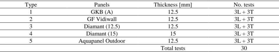
Table 1. Test matrix for the bending tests on panels
Type Panels Thickness [mm] No. tests
1 GKB (A) 12.5 3L + 3T
2 GF Vidiwall 12.5 3L + 3T
3 Diamant (12.5) 12.5 3L + 3T
4 Diamant (15) 15 3L + 3T
5 Aquapanel Outdoor 12.5 3L + 3T Total tests 30 L: longitudinal direction; T: transverse direction
The screws adopted for panel-to-frame connections will be tested in order to obtain the shear strength. Therefore, the following screw typology are considered: (i) 3.5 mm diameter flat trumpet
outside-to-outside lip size) lipped channel stud sections. Each panel will be connected to the stud using two screws with edge distance equal to 15 mm. Finally, the load will be applied by means of two steel holders, each of which will be bolted to the stud with four M8 8.8 grade bolts. Table 3 provides the test matrix.
Fig. 1 Test set-up for bending tests on panels
Fig. 2 Test set-up for shear tests on screws
[image:4.595.70.555.301.386.2]Fig. 3 Test set-up for shear tests on panel-to-frame connections Table 2. Test matrix for the shear tests on screws
Type Screws Head type Diameter [mm] Length [mm] No. tests 1 TN 3.5x35 Flat trumpet head 3.5 35 6 2 3.5x40 Flat countersunk trim head 3.5 40 6 3 XTN 3.9x38 Flat trumpet head 3.9 38 6 4 SN 4.2x39 Flat countersunk head 4.2 39 6
5 FN 4.3x65 Lath head 4.3 65 6
[image:4.595.73.551.413.577.2]Total tests 30
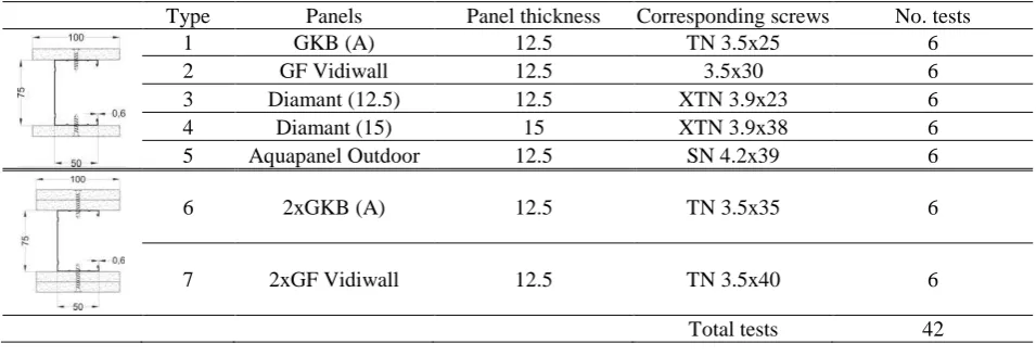
Table 3. Test matrix for the shear tests on panel-to-frame connection
Type Panels Panel thickness Corresponding screws No. tests
1 GKB (A) 12.5 TN 3.5x25 6
2 GF Vidiwall 12.5 3.5x30 6 3 Diamant (12.5) 12.5 XTN 3.9x23 6 4 Diamant (15) 15 XTN 3.9x38 6 5 Aquapanel Outdoor 12.5 SN 4.2x39 6
6 2xGKB (A) 12.5 TN 3.5x35 6
7 2xGF Vidiwall 12.5 TN 3.5x40 6
Total tests 42
3 IN-PLANE QUASI-STATIC REVERSED CYCLIC TESTS ON PARTITION
DRYWALLS
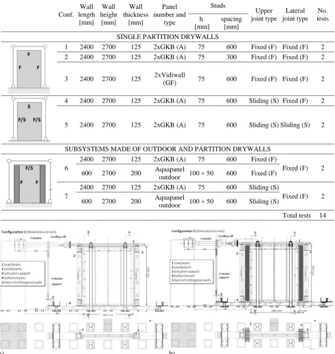
interposing of any material (concrete, steel, wood) between the tested partition drywalls and steel testing frame, in such a way to give the possibility to simulate a large range of partition-to-structure interface behaviour. In particular, for this experimental campaign, concrete bricks have been selected as interface elements, in order to reproduce the behaviour of partition drywalls within reinforced concrete framed buildings. The drywall prototype will be constrained to the laboratory floor on the bottom beam of testing frame. Horizontal displacements will be applied to the top beam (loading beam) of testing frame. Two hinged rectangular hollow vertical profiles are placed at the two ends of the partition in order to simulate the columns behaviour of a building structure. The out-of-plane displacements will be avoided by two steel portal frames equipped with roller wheels. Moreover, a sliding-hinge will be placed between the loading actuator and the loading beam, in order to avoid vertical load components. The tests will be performed by using a hydraulic load actuator having 500 mm stroke and 500 kN load capacity.
Table 4. Test matrix for the in plane drywall tests.
Conf. Wall length
[mm] Wall height
[mm]
Wall thickness
[mm]
Panel number and
type
Studs
Upper joint type
Lateral joint type
No. tests h
[mm]
spacing [mm]
SINGLE PARTITION DRYWALLS
1 2400 2700 125 2xGKB (A) 75 600 Fixed (F) Fixed (F) 2 2 2400 2700 125 2xGKB (A) 75 300 Fixed (F) Fixed (F) 2
3 2400 2700 125 2xVidiwall
(GF) 75 600 Fixed (F) Fixed (F) 2
4 2400 2700 125 2xGKB (A) 75 600 Sliding (S) Fixed (F) 2
5 2400 2700 125 2xGKB (A) 75 600 Sliding (S) Sliding (S) 2
SUBSYSTEMS MADE OF OUTDOOR AND PARTITION DRYWALLS
6
2400 2700 125 2xGKB (A) 75 600 Fixed (F)
Fixed (F) 2 600 2700 200 Aquapanel
outdoor 100 + 50 600 Fixed (F)
7
2400 2700 125 2xGKB (A) 75 600 Sliding (S)
Fixed (F) 2 600 2700 200 Aquapanel
outdoor 100 + 50 600 Sliding (S)
Total tests 14
a) b)
4 OUT-OF-PLANE QUASI-STATIC MONOTONIC TESTS ON PARTITION DRYWALLS
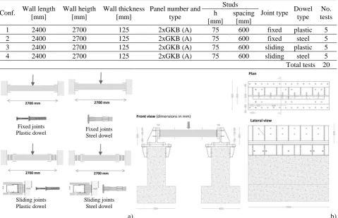
[image:6.595.75.555.269.578.2]The out-of-plane quasi-static monotonic tests are aimed to evaluate the partition drywall strength to be used in Eurocode 8 [16] for non-structural elements verifications. The three-point bending tests will be carried out on four configurations of single partition drywalls (I). The investigated variables are: (i) the joint between partition drywalls and reinforced concrete building structure (fixed or sliding), (ii) the dowel type used to realize the joints (plastic or steel). All the partition specimens are 2400 mm x 2700 mm (length x height). Five tests for each configuration will be carried out, for a total number of 20 tests. The tests on the drywall prototypes will be performed in a horizontal position using a test set-up specifically developed (Fig. 6). The specimens will be connected by means of two steel profiles, having 300x300 (web depth x flange size) T-shaped cross section, to the reinforced concrete supports. Also in this case, the set-up has been designed in order to allow the interposing of concrete blocks. The test matrix is shown in Table 5.
Table 5. Test matrix for the out-of-plane monotonic tests on partition drywalls
Conf. Wall length [mm]
Wall heigth [mm]
Wall thickness [mm]
Panel number and type
Studs
Joint type Dowel type
No. tests h
[mm]
spacing [mm]
1 2400 2700 125 2xGKB (A) 75 600 fixed plastic 5 2 2400 2700 125 2xGKB (A) 75 600 fixed steel 5 3 2400 2700 125 2xGKB (A) 75 600 sliding plastic 5 4 2400 2700 125 2xGKB (A) 75 600 sliding steel 5 Total tests 20
Fixed joints
Plastic dowel Fixed joints Steel dowel
Sliding joints Plastic dowel
Sliding joints Steel dowel
a) b)
Fig. 6 a) Joint and dowel types; b) Test set-up for out-of-plane quasi-static monotonic tests
5 DYNAMIC TESTS ON SHAKING TABLE ON FULL-SCALE SYSTEMS
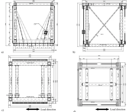
configurations will be considered (Fig. 7a,b): (i) fixed joints all along the drywall perimeter and (ii) fixed joints along the drywall vertical sides and sliding joint at the top drywall horizontal side. The second specimen configuration is representative of a constructive systems consisting of two partition drywalls, two outdoor drywalls and a suspended ceiling (IV). In this case, the outdoor drywalls will be placed in the set-up frame along the testing direction, while the partition drywalls will be directly connected to them in perpendicular direction. The outdoor drywalls are 2400x2700 mm (length x height), while the partition drywalls are 2300x2700 mm (length x height). In the top field between the drywalls, a suspended continuous plasterboard ceiling will be installed. Also in this case, the two joint configuration above defined will be considered (Fig.7c,d). Table 6 summarises the test program and the different specimen configurations.
Testing frame Fixed joints Partition wall 2 7 0 0 m m 2400 mm Testing frame Sliding joints Partition wall Fixed joints 2 7 0 0 m m 2400 mm Testing frame Exterior wall 2 7 0 0 m m 2400 mm Fixed joints Partition wall Ceiling Testing frame Exterior wall 2 7 0 0 m m 2400 mm Sliding joints Ceiling Partition wall Fixed joints
a) Fixed single drywalls b) Sliding single drywalls c) Fixed coupled drywalls and ceiling
[image:7.595.48.524.210.318.2]d) Sliding coupled drywalls and ceiling
Fig.7 Specimen configurations
Table 6. Programme of shaking table tests
The shaking table tests will be performed by using a purposely designed set-up structure. The set-up is a versatile 3D steel frame, which has been designed with aim of simulating the elastic behaviour, in terms of mass and stiffness, of different building interstorey. The lateral structural system of the 3D steel frame, along the loading direction, is a special eccentric bracing system with pre-tensioned diagonals (Fig. 8a). In fact, its diagonals can have different slope (angles from 64° to 83°) and cross-section area, in such a way to allow to the system different lateral stiffness. Therefore, changing the applied mass together to the variation of lateral stiffness, it is possible to obtain SDOF systems with a large range of period values. In order to obtain a structural response in the elastic range, the diagonals must not be loaded by an axial compression. In addition, the yielding stress of the diagonal members must exceed the maximum acting tension stress, which is a function of the maximum interstorey drift achieved during the test. Therefore, considering interstory drift angles of about 1%, diagonal members made of a ultra high strength steel grade (yielding and ultimate strength equal to 1200 and 1500 MPa, respectively) are required. In these diagonal members the
Conf System Position System type Wall length Wall height Wall thick. Panel number and type
Studs Upper joint type Lateral joint type No. tests h spacing
[mm] [mm] [mm] [mm] [mm]
1
Load direction Partition 2400 2700 125 2xGKB (A) 75 600 fixed fixed 1 Perp. direction Partition 2200 2700 125 2xGKB (A) 75 600 fixed fixed
Ceiling - - - -
2
Load direction Partition 2400 2700 125 2xGKB (A) 75 600 sliding fixed 1 Perp. direction Partition 2200 2700 125 2xGKB (A) 75 600 sliding fixed
Ceiling - - - -
3
Load direction Outdoor 2400 2700 200 Aquapanel outdoor
100+
50 600 fixed fixed 1 Perp. direction Partition 2300 2700 125 2xGKB (A) 75 600 fixed fixed
Ceiling Susp. ceiling - - - Diamant 15 - - - -
4
Load direction Outdoor 2400 2700 200 Aquapanel outdoor
100+
50 600 sliding fixed 1 Perp. direction Partition 2300 2700 125 2xGKB (A) 75 600 sliding fixed
[image:7.595.41.530.365.587.2]preloading force is applied by means the tightening of a system composed by three M39 high strength bolts. The 3D frame is stabilized in the direction perpendicular to the load by means of a X-bracing system in which the diagonals are made of S355 steel rods (Fig. 8b).
The base of the set-up frame is a grid of rectangular hollows beams connected to the base plate of the shaking table. In particular, these beams are arranged in such a way to provide a base for the different specimen configurations (Fig. 8c). A similar grid of beams, made with HEB 200 profiles, defines the top level of the set-up frame (Fig. 8d). On the top of this grid, steel plates are welded in order to provide a restraint for the concrete blocks, which reproduce the mass of the system. The bottom and top beam grids are connected by means of four hinged columns, having 200x200x14.2 mm hollow sections. The columns hinges are unidirectional along the loading direction. All the frame elements are made of S355 steel grade, with exception of the hinges plates, which are realized with S460 steel grades. Beams and columns have holes on the surfaces in contact with the partition/outdoor drywalls, in order to interpose the bricks that simulate the interface with a reinforced concrete building structure.
a) b)
c)
[image:8.595.84.527.256.647.2]d)
Fig. 8 Set-up for shaking table tests: a) special eccentric bracing system, b) X-bracing system; c) bottom beam grid, d) top beam grid
6 CONCLUSIONS
The paper presents the planning of a very extensive experimental campaign devoted to study the seismic response of non-structural building components produced by Knauf company, consisting of partition drywalls, outdoor drywalls, and suspended continuous plasterboard ceilings. The main activities of the research will involve tests on materials and main components, quasi-static tests on partition/outdoor drywalls and shaking table full-scale tests on whole systems made of partition
drywalls, outdoor drywalls and suspended ceilings. In particular, for each test typology, test matrix, specimens and prototypes and tests set-up are described in the paper.
ACKNOWLEDGMENT
The authors acknowledge the Knauf company for the financial support to the research activity.
REFERENCES
[1] Lee, TH, Kato, M, Matsumiya, T, Suita, K, Nakashima, M. “Seismic performance evaluation of non-structural components: drywall partitions”. Earthquake Engineering and Structural Dynamics 2006; 36(3):367–82.
[2] Restrepo, JI, Bersofsky, AM. “Performance characteristics of light gage steel stud partition walls”.
Thin-Walled Structures 2011; 49: 317–324.
[3] Tasligedik, AS, Pampanin, S; Palermo, A. “In-plane cyclic testing of non-structural drywalls infilled
within RC frames”. Proc. of 15th World Conference on Earthquake Engineering, Lisboa, Portugal, 2012.
[4] Retamales, R, Davies, R, Mosqueda, G, Filiatrault, A. “Experimental seismic fragility of cold-formed
steel framed gypsum partition walls”. Journal of structural Engineering 2013; 139: 1285-1293.
[5] Magliulo, G, Petrone, C, Capozzi, V, Maddaloni, G, Lopez, P, Manfredi, G. “Seismic performance
evaluation of plasterboard partitions via shake table tests”. Bull Earthquake Eng 01/2013.
[6] Badillo-Almaraz, H, Whittaker, AS, Reinhorn, AM. “Seismic qualification and fragility testing of
suspended ceiling systems”. Proc. of 13th World Conference on Earthquake Engineering, Vancouver,
B.C., Canada, 2004.
[7] Magliulo, G, Pentangelo, V, Maddaloni, G, Capozzi, V, Petrone, C, , Lopez, P,Talamonti, R, Manfredi,
G.” Shake table tests for seismic assessment of suspended continuous ceilings”. Bull Earthquake Eng
2012; 10:1819–1832.
[8] Gilani, ASJ, Takhirov, SM, Tedesco, L. “Seismic evaluation procedure for suspended ceilings and
components new experimental approach”. Proc. of 15th World Conference on Earthquake Engineering,
Lisboa, Portugal, 2012.
[9] Soroushian, S, Ryan, KL, Maragakis, M, Wieser, J, Sasaki, T, sato, E, Okazaki, T, Tedesco, L, Zaghi, AE, Mosqueda, G, Alvarez, D. "NEES/E-Defense Tests: Seismic performance of ceiling/ sprinkler
piping nonstructural systems in base isolated and fixed base building”. Proc. of 15th World Conference
on Earthquake Engineering, Lisboa, Portugal, 2012.
[10] Filiatrault, A, Mosqueda, G, Reinhorn, A, Pitan, M, Weinreber, S, Retamales, R. “Preliminary Report Seismic Performance Assessment of a Full-Scale Hospital Emergency Room”. UB-NCS Preliminary Results ER Tests – 2/4/2008.
[11] McCormick, J, Matsuoka, Y, Pan, P, Nakashima, M. “Evaluation of Non-Structural Partition Walls and
Suspended Ceiling Systems through a Shake Table Study”. Structures Congress, Vancouver, British
Columbia, Canada, 2008.
[12] UNI EN ISO 6892-1, Metallic materials - Tensile testing - Part 1: Method of test at room temperature. European Committee for Standardization, 2009.
[13] UNI EN 520, Gypsum plasterboards - Definitions, requirements and test methods. European Committee for Standardization, 2009.
[14] Fiorino, L, Iuorio, O, Macillo, V, Landolfo, R. “Evaluation of shear and tension strength of self-drilling
screws by experimental test”, Proc. of 6th International Conference on Thin Walled Structures,
Timisoara, Romania, 2011.