Understanding Coordinate Reference Systems, Datums
and Transformations
Janssen, V., 1,2
1Surveying and Spatial Sciences, School of Geography and Environmental Studies, University of Tasmania
Private Bag 76, Hobart TAS 7001, Australia
2 Survey Infrastructure and Geodesy, NSW Land and Property Management Authority, 346 Panorama
Avenue, Bathurst NSW 2795, Australia, E-mail: [email protected]
Abstract
Spatial professionals are required to deal with an increasingly wide range of positioning information obtained from various sources including terrestrial surveying, Global Navigation Satellite System (GNSS) observations and online GNSS processing services. These positions refer to a multitude of local, national and global datums. A clear understanding of the different coordinate reference systems and datums in use today and the appropriate transformations between these is therefore essential to ensure rigorous consideration of reference frame variations in order to produce high-quality outcomes in spatial data analysis tasks. This paper provides a compendium for spatial practitioners and Geographic Information System (GIS) users, reviewing the concepts and definitions of coordinate reference systems and datums, and outlining the practical procedures for coordinate transformations in relation to both horizontal and vertical datums.
1. Introduction
The increasing use of Global Navigation Satellite System (GNSS) technology, online GNSS processing services and Geographic Information System (GIS) analysis tools requires spatial professionals to be familiar with a wide range of positioning information derived from various data sources and referenced to different national and global datums. Routinely, numerous datasets need to be integrated for spatial data analysis tasks, e.g. in order to investigate environmental change, manage national security and contribute to hazard mitigation and emergency management. High-quality coordinate transformations have become essential in practice to ensure that dynamic datum effects caused by tectonic plate motion and other geophysical phenomena are considered appropriately and the high precision and/or accuracy of the observations is not sacrificed during the transformation process. This paper reviews the concepts and definitions of coordinate reference systems and datums. It provides a compendium for spatial practitioners, identifying and detailing the procedures necessary to perform coordinate transformations, in regards to both horizontal and vertical datums. The following distinction is made between the terms conversion and transformation. A conversion describes a change of the coordinate system and does not include a change of the datum, e.g. a conversion between Cartesian and curvilinear coordinates relating to the same datum. A transformation describes a change of the datum and
does not include a change of the coordinate system, e.g. a transformation of a set of coordinates given in a particular coordinate system between two datums. In practice, both often have to be used in tandem since positions given in a certain coordinate system in Datum 1 are required to be transferred into positions given in a different coordinate system in Datum 2.
2. Shape of the Earth
the geoid, either locally or on a global basis (Figure 1). The inverse flattening is often used in conjunction with a to define the reference ellipsoid. The amount of ellipsoid flattening (f) can be determined by:
(
) /
f
=
a b a
−
Equation 1 Spatial professionals often have to deal with several ellipsoids, e.g. when older spatial datasets are to be combined with recent positions obtained from GNSS observations. The Geodetic Reference System 1980 (GRS80) and the World Geodetic System 1984 (WGS84) ellipsoids are both global earth models. The former has been widely accepted as international standard, while the latter is the nominal reference ellipsoid used by the Global Positioning System (GPS). These ellipsoids are geocentric, i.e. their origin coincides with the
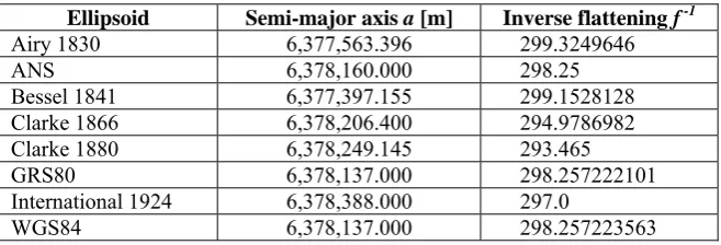
[image:2.595.146.451.289.484.2]Earth’s centre of mass (including the Earth’s oceans and atmosphere), called the geocentre. Prior to the advent of space geodetic techniques such as GPS, it had not been possible to realise geocentric coordinate reference systems in practice. Consequently, several ellipsoids were designed as a locally best fit to the geoid in a certain region, e.g. the Clarke 1866 ellipsoid for North America, the Bessel 1841 ellipsoid for Europe and the Australian National Spheroid (ANS). These ellipsoids are non-geocentric and generally exhibit a significant offset from the geocentre, e.g. ~200 m in the case of the ANS. Table 1 lists the defining parameters of several ellipsoids routinely encountered today. The GRS80 and WGS84 ellipsoids only exhibit a very small difference in the flattening parameter, affecting 3-dimensional coordinates at the sub-millimetre level, and can therefore be assumed identical for most practical purposes (ICSM, 2002).
Figure 1: Several ellipsoids approximating the geoid (adapted from Iliffe and Lott, 2008)
Table 1: Parameters of selected ellipsoids used for mapping purposes
Ellipsoid Semi-major axis a [m] Inverse flattening f -1 Airy 1830 6,377,563.396 299.3249646
ANS 6,378,160.000 298.25
Bessel 1841 6,377,397.155 299.1528128 Clarke 1866 6,378,206.400 294.9786982 Clarke 1880 6,378,249.145 293.465
GRS80 6,378,137.000 298.257222101
International 1924 6,378,388.000 297.0
[image:2.595.134.463.539.651.2]3. Coordinate Reference Systems
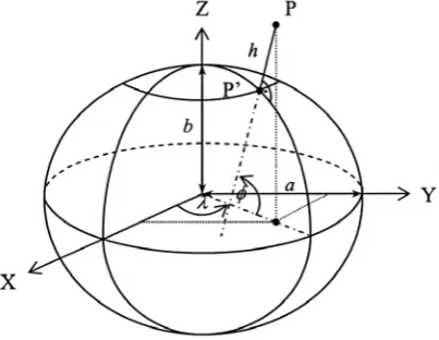
[image:3.595.82.284.229.385.2]A coordinate reference system is a methodology to define the location of a feature in space. On the ellipsoid, positions are either expressed in Cartesian coordinates (X, Y, Z) or in curvilinear coordinates (φ, λ, h), i.e. geodetic latitude, longitude and ellipsoidal height (Figure 2). In a geocentric, rectangular Cartesian coordinate system the Z-axis coincides with the position of the Earth’s rotation axis at a certain instant in time (epoch). The X-axis passes through the intersection of the Greenwich meridian and the equator, and the Y-axis completes a right-handed coordinate system by passing through the intersection of the 90°E meridian and the equator.
Figure 2: Ellipsoidal coordinate reference systems
In regards to curvilinear coordinates, geodetic latitude is defined as the angle in the meridian plane between the equatorial plane and the ellipsoid normal through a point P. Geodetic longitude is measured in the equatorial plane as the angle between the Greenwich meridian (X-axis) and the meridian through P, while the ellipsoidal height is measured from the ellipsoid surface along the ellipsoid normal. It is important to note that a single ground point can have different geodetic coordinates depending on which ellipsoid the coordinate system refers to. Curvilinear coordinates can easily be converted into Cartesian coordinates by (e.g. Vaniček and Krakiwsky, 1986):
2
( ) cos cos ( ) cos sin
( (1 ) )sin
X h
Y h
Z e h
ν
φ
λ
ν
φ
λ
ν
φ
+
⎡ ⎤ ⎡ ⎤
⎢ ⎥ ⎢= + ⎥
⎢ ⎥ ⎢ ⎥
⎢ ⎥ ⎢ − + ⎥
⎣ ⎦ ⎣ ⎦
Equation 2
where ν represents the radius of curvature in the prime vertical:
2 2
1 sin
a e
ν
φ
=−
Equation 3 The quantities a and e2 = 2f – f2 denote the length of
the semi-major axis and the squared first eccentricity of the ellipsoid, respectively, defining the size and shape of the reference ellipsoid. The inverse conversion is not as straight forward and generally requires iteration (e.g. Torge, 2001):
[
]
1
1 2
2 2
1
2 2
tan 1
tan /
sec Z
e h
X Y
Y X
h X Y
ν φ
ν λ
φ ν
− −
−
⎡ ⎛ ⎛ ⎞⎞ ⎤
= ⎢ ⎜ − ⎜ ⎟⎟ ⎥
+
⎝ ⎠
⎝ ⎠
+
⎢ ⎥
⎣ ⎦
=
= + ⋅ −
Equation 4 However, since ν >> h, the iteration converges quickly. It should be noted that λ cannot be determined for X = 0. Numerous alternative approaches have been developed, such as the non-iterative method by Bowring (1985) and the vector method by Pollard (2002), but will not be discussed here. For a comparison of various different methods and their computational efficiency the reader is referred to, e.g., Seemkooei (2002) and Fok and Iz (2003). In addition, local (topocentric) coordinate systems exist, such as the north-east-up (n, e, u) system routinely utilised in geodesy (e.g. Soler, 1998 and Hofmann-Wellenhof et al., 2001), but these are generally not used by the GIS community. 4. Coordinate Datums
4.1 ITRF
The International Terrestrial Reference Frame (ITRF) is the most precise earth-centred, earth-fixed datum currently available and was first introduced in 1988. It is maintained by the International Earth Rotation and Reference Systems Service (IERS) and realised by an extensive global network of accurate coordinates and their velocities derived from geodetic observations using GPS, Very Long Baseline Interferometry (VLBI), Satellite Laser Ranging (SLR), Lunar Laser Ranging (LLR) and Doppler Orbitography and Radiopositioning Integrated by Satellite (DORIS) (Altamimi et al., 2007). These coordinates are based on the GRS80, a geocentric ellipsoid designed to approximate the geoid on a global scale. The ITRF is a dynamic datum and changes according to temporal variations of its network coordinates and their velocities due to the effects of crustal motion, earth orientation, polar motion and other geophysical phenomena such as earthquakes and volcanic activity (Bock, 1998). It is updated regularly in order to account for the dynamics of the Earth and now sufficiently refined to ensure that the change between successive ITRF versions is in the order of 1-2 cm. So far the following versions have been released: ITRF88, ITRF89, ITRF90, ITRF91, ITRF92, ITRF93, ITRF94, ITRF96, ITRF97, ITRF2000 and ITRF2005. A new version, ITRF2008, is anticipated to be released in the near future. Coordinates given in any of the ITRF realisations are referred to a specific epoch in order to enable appropriate consideration of the Earth’s dynamics.
4.2 WGS84
The World Geodetic System 1984 (WGS84) was developed for the U.S. Defense Mapping Agency (DMA), later named NIMA (National Imagery and Mapping Agency) and now called NGA (National Geospatial-Intelligence Agency), and is the nominal datum used by GPS (NIMA, 2004). It is based on the WGS84 ellipsoid which can generally be assumed identical to the GRS80 (see Table 1). The WGS84 datum was introduced in 1987 based on Doppler observations and has since been refined several times to be closely aligned with the ITRF in order to prevent degradation of the GPS broadcast ephemerides (i.e. orbit parameters) due to plate tectonics (True, 2004). The first refinement was introduced in 1994 to align the WGS84 with ITRF91 and included a revised set of station coordinates for the tracking network, based entirely on GPS observations (Malys and Slater, 1994). It is known as WGS84 (G730) where G stands for ‘GPS’ and 730 denotes the GPS week number when NGA started expressing their derived GPS precise
ephemerides in this frame, i.e. 2 January 1994. Swift (1994) estimated that the refined WGS84 agreed with the ITRF92 at the 10 cm level. The second refinement, WGS84 (G873), occurred on 29 September 1996 and resulted in coincidence with the ITRF94 at better than 10 cm (Malys et al., 1997). It should be noted that the GPS Operational Control Segment did not implement the WGS84 (G730) and WGS84 (G873) coordinates until 29 June 1994 and 29 January 1997, respectively. The latest refinement, WGS84 (G1150), was introduced and implemented on 20 January 2002 based on 15 days of GPS data collected during February 2001 at six U.S. Air Force monitoring stations, 11 NGA stations and several additional global tracking stations. After this alignment with the ITRF2000, it was shown that the WGS84 coincides with the ITRF within a few centimetres at the global level (Merrigan et al., 2002). For all mapping and charting purposes, the WGS84 and the most current ITRF can therefore be assumed identical (NIMA, 2004). However, it should be noted that the level of agreement worsens as the time gap between WGS84 (G1150) and the latest realisation of ITRF grows. 4.3 AGD66/84 and GDA94
differential GPS applications within Australia, as both ends of a baseline move at the same rate. Positions referred to the GDA94 appear to be about 200 m north-east of those referenced to the AGD, which is mainly due to the origin shift between the respective ellipsoids (ICSM, 2002).
4.4 NAD27 and NAD83
The North American Datum 1927 (NAD27) was the first continental reference datum for North America, based on the non-geocentric Clarke 1866 ellipsoid with an origin station at Meades Ranch in Kansas, close to the geographical centre of the contiguous United States. In 1986 it was replaced by the NAD83, which is also a stationary datum but based on the GRS80 ellipsoid and therefore compatible with GPS observations (Schwarz and Wade, 1990). The original version, referred to as NAD83 (1986) and based on terrestrial measurements supplemented by Doppler, VLBI and SLR observations, suffered from a lack of accuracy and has since undergone several updates. From 1989, each U.S. state established regional reference frames using GPS, known as High Accuracy Reference Networks (HARN), which were combined in the second realisation NAD83 (HARN). Starting in 1994, further realisations were introduced based on a growing national GPS network of continuously operating reference stations (CORS). These realisations resulted from transforming the then current ITRF coordinates of numerous CORS sites to NAD83 and are referred to as NAD83 (CORS93), NAD83 (CORS94) and NAD83 (CORS96), the respective year indicating which ITRF frame was used. In 2007, a nationally consistent readjustment of the National Spatial Reference System (NSRS) using GPS data collected over 20 years was completed, resulting in the NAD83 (NSRS2007) realisation which densifies the more rigorously defined NAD83 (CORS96) (Vorhauer, 2007). It should be noted that the evolution of NAD83 progressed differently in Canada (Craymer, 2006). 4.5 ED50 and ETRS89
The European Datum 1950 (ED50) was developed after World War II and has been used for much of Western Europe. It is based on the International (Hayford) Ellipsoid 1924 with an origin station at the Helmert Tower in Potsdam, Germany (Seeger, 1994). The datum was improved over the next four decades with ED79 and ED87 solutions computed on the same ellipsoid (Poder and Hornik, 1989). In order to move to a geocentric (i.e. GPS-compatible) datum, the European Terrestrial Reference System 1989 (ETRS89) was introduced in 1989. This datum is based on the GRS80 ellipsoid, coincident with
ITRF89 at epoch 1989.0 and realised by an extensive permanent GPS station network across Europe (Boucher and Altamimi, 1992). The ETRS89 has undergone several realisations, denoted European Terrestrial Reference Frames (ETRF), relating it to more recent versions of the ITRF. The latest realisation, known as ETRF2000, has been derived from the ITRF2000 through a set of known transformation formulae (Altamimi and Boucher, 2002). While many European countries continue to use their individual national datums, an increasing number of these are linked to the ETRF.
5. Projection Coordinates
In practice, it is often required to express positions on a flat surface in the form of grid coordinates, i.e. in a 2-dimensional Cartesian coordinate system such as Easting and Northing. This section briefly reviews map projections and introduces the principle of grid coordinates. A detailed treatment of this topic can be found in texts such as Snyder (1987), Maling (1993), Bugayevskiy and Snyder (1995) and Grafarend and Krumm (2006).
5.1 Map Projections
maps therefore allow the analysis, control or recording of motion and angular relationships. Two well known conformal projections are the Lambert Conformal Conic and the Transverse Mercator projection, which are used extensively around the world as a basis for grid coordinates and are therefore treated in more detail here.
5.2 LCC Projection
The Lambert Conformal Conic (LCC) projection is mathematically derived and employs a normal cone that is either tangent or secant to the Earth, i.e. touching it along one or two standard parallels. All meridians are represented by straight lines that meet at the tip of the cone outside the limits of the map projection. All parallels are sections of concentric circles centred at the tip of the cone with their radii differing as a function of latitude. The scale is true (i.e. unity) along the standard parallel(s) and varies from north to south but not from east to west. Hence the zone widths are only limited in the north-south direction. If two standard parallels are used, the scale factor is less than 1.0 between them and exceeds 1.0 outside the standard parallels. Since area deformation between and near the standard parallels is relatively small, the LCC projection can provide exceptionally good directional and shape relationships within such a zone. It is ideal for mapping areas of small latitudinal range that extend long distances in an east-west direction and is therefore often applied in the United States.
5.3 UTM Projection
The Transverse Mercator projection is mathematically derived and utilises a cylinder that is tangent to a chosen meridian, called the central meridian (CM). The scale is therefore true along the central meridian but increases with increasing distance from it, thereby causing a growing distortion in scale. The Transverse Mercator projection is most appropriate for regions exhibiting a large north-south extent but small east-west extent. However, by splitting up the area to be mapped into longitudinal zones of limited extent and merging the resulting plane maps, the entire world can be mapped with minimal distortion. The Universal Transverse Mercator (UTM) projection utilises a zone width of 6° and ensures that the scale is very close to unity across the entire zone by defining a central scale factor of 0.9996 for the CM which results in a scale of 1.0010 at the zone boundary located 3° away from the CM. The UTM projection divides the world into 60 zones, zone 1 having a CM at longitude 177°W, while the latitudinal extent of each zone is 80°S and 84°N, indicated by 20 bands labelled C to X with the exclusion of I and O
for obvious reasons. All latitude bands are 8° wide, except the most northerly (X) which is 12° wide to allow Greenland to be mapped in its entirety. For a UTM map of the world, the reader is directed to
http://www.dmap.co.uk/utmworld.htm. The increasing distortion in scale evident at high latitudes is caused by the north-south gridlines not converging at the poles, i.e. the poles would be projected as lines rather than points. The island of Tasmania, e.g., is located in zone 55G. Note that while the latitude extent is generally part of the coordinate display in most GNSS receivers, in a GIS environment it is often replaced by N or S to indicate the hemisphere when a global UTM system is used.
5.4 Grid Coordinates
datum and/or projection, while new datums can easily be defined.
6. Datum Transformations
The coordinates of a point will differ depending on which datum these coordinates refer to. Several coordinate transformations exist and their accuracy depends on the method chosen as well as the number, distribution and accuracy of the common points used to determine the transformation parameters. It is generally recommended to use the most accurate method available, although it is recognised that less accurate options may be sufficient for certain applications.
6.1 Grid Transformation
The most accurate method is the grid-based approach which supplies users with transformation parameters and, being a particularly useful benefit of this technique, transformation accuracy (not to be confused with the accuracy of the transformed coordinates) on a regularly spaced grid. The transformation components of any point within the grid are generally determined based on bi-linear interpolation using the known components of the four surrounding grid nodes. In Australia, for instance, a complex model is employed for the AGD-GDA transformation which combines a datum shift based on a 7-parameter similarity transformation (see section 6.2) with the modelling of distortions caused by the surveying techniques employed in the datum realisations of the AGD. This is achieved by utilising grids that have been developed using the method of least squares collocation, which allows the contribution of the distortion at surrounding data points to be weighted according to their distance from the interpolation point (Collier, 2002). The advantage of these grids is that a complex transformation model with a high accuracy can be implemented in a relatively routine fashion. The user only has to perform a simple interpolation to obtain coordinate shifts, followed by a simple addition to perform the transformation. The user friendliness of these grids has led to their adoption in several countries such as the U.S., Canada and Australia. An analysis of the errors introduced by the use of such transformation grids is provided by Nievinski and Santos (2007). In Australia, it was found that distortions for the transformation between AGD66/84 and GDA94 reach several metres, especially in the more remote regions of the country (Collier, 2002). If the distortion pattern across an area is regular, high transformation accuracy can be achieved, while an irregular distortion pattern will cause the transformation accuracy to deteriorate.
Generally, the transformation accuracy of the AGD66/84-GDA94 grids is better than ±0.1 m, although it decreases to ±0.5 m or more in some cases (Collier, 2002). National transformation grids for the transformation between the two realisations of the AGD and GDA94 are provided by ICSM (2002) and supersede previous state-wide grids. These grids utilise the National Transformation Version 2 (NTv2) format developed by the Geodetic Survey Division of Geomatics Canada which is now being used in many GIS software packages. The NTv2 format was chosen because it enables accuracy estimates of the transformation parameters to be included and allows sub-grids of different density which is very useful when dealing with variable distortion patterns (Collier, 2002). Australian state jurisdictions have developed readily available transformation software that utilises these grids. One of these programs, DatumTran, has been specifically designed to transform GIS data in various formats (LPMA, 2008). In the United States, NADCON, the standard NAD27-NAD83 datum transformation program created by the U.S. National Geodetic Survey (NGS), performs grid transformations for curvilinear coordinates with an accuracy of about ±0.15-0.50 m (Mulcare, 2004a; NGS, 2004a).
6.2 Similarity Transformation
A 7-parameter similarity transformation, also known as Helmert transformation, accounts for the difference between two 3-dimensional datums by applying three translations along the coordinate axes, three rotations about the axes and one scale factor change (e.g. Harvey, 1986):
(
)
2 1
2 1
2 1
1
1 1
1
Δ −
⎡ ⎤ ⎡ ⎤ ⎡ ⎤ ⎡ ⎤
⎢ ⎥ ⎢= Δ ⎥+ + ⎢− ⎥ ⎢ ⎥
⎢ ⎥ ⎢ ⎥ ⎢ ⎥ ⎢ ⎥
⎢ ⎥ ⎢Δ ⎥ ⎢ − ⎥ ⎢ ⎥
⎣ ⎦ ⎣ ⎦ ⎣ ⎦ ⎣ ⎦
X X X
Y Y s Y
Z Z Z
γ β
δ γ α
β α
Equation 5 where (X1, Y1, Z1) and (X2, Y2, Z2) are the
coordinates of a point in Datum 1 and Datum 2 respectively, ΔX, ΔY, ΔZ are the coordinates of the origin of Datum 2 in Datum 1 (i.e. origin shift), α,
reversed. By convention, a positive rotation is an anti-clockwise rotation when viewed along the positive axis towards the origin. Since this transformation is based on Cartesian coordinates, geodetic coordinates first need to be converted using equation (2). The transformed Cartesian coordinates can then be converted back via equation (4), effectively allowing curvilinear coordinates to be transformed between two datums. The similarity transformation is also known as a conformal transformation because it maintains the shape (but not the orientation and size) of the transformed objects. If a dynamic datum is involved in the transformation, e.g. between different realisations of the ITRF or between the GDA94 and a particular ITRF, the velocities of the seven parameters need to be taken into account in order to refer the parameters to the desired epoch. This 14-parameter similarity transformation can be performed according to Dawson and Steed (2004). Alternatively, equation (5) can be used after the parameters have been updated according to (IERS, 2008):
0 0
( ) ( ) (= + ⋅ − ) P t P t P t t
Equation 6 where P(t) is the parameter at the desired epoch t (i.e. observation epoch), P(t0) is the parameter at the
epoch t0 of its initial definition, and P is the rate
(velocity) of this parameter. The epoch is given in decimal years. The similarity transformation can model the differences between various ITRF realisations at the cm level, provided the rates are applied to account for tectonic plate motion (Dawson and Steed, 2004). The required parameters and their rates can be obtained from the ITRF website (IERS, 2008). Transformation accuracies of about 1 m can be achieved for AGD66/84-GDA94 transformations, using the parameters given in ICSM (2002). The parameters for similarity transformations between various European datums are available from CRS (2008), while those needed for datums used in North America can be obtained from the extensive body of literature (e.g. Soler and Marshall, 2003; Craymer, 2006).
6.3 Lower Accuracy Methods
Lower accuracy methods, such as the Molodensky and abridged Molodensky formulae or a simple block shift, provide transformation accuracies at the 5-10 m level (e.g. ICSM, 2002). However, these will not be discussed here since the more accurate methods are generally preferred in practice. An extensive evaluation of different models using
published parameters to transform from AGD to GDA94 was presented by Kinneen and Featherstone (2004) and can be consulted for more details on these methods.
6.4 Transformations within the GIS Environment These projections and transformations can generally be performed within the GIS environment. However, it is important to understand the difference between GIS tools that merely define a projection (e.g. if a shapefile has lost its projection or datum information) and tools that actually perform a projection and/or transformation and thus change the dataset. In addition, on-the-fly projections and transformations can be used efficiently to correctly display data given in different datums. However, the user needs to be aware that this tool only changes the display and does not alter the original dataset, hence it should not be used for spatial data analysis. It should be obvious that datum information is a crucial component of the metadata attached to any spatial dataset.
7. Vertical Datums
A vertical datum defines a reference for elevation comparisons and is essential for a wide range of spatial applications such as floodplain management, waterway navigation management, roadway and drainage design, agricultural management and surveying in general. Most countries utilise an approximation of the orthometric height system related to the geoid as reference for vertical coordinates. Generally, vertical datums are based on MSL. However, MSL has been specified differently in different countries, resulting in a multitude of zero-levels. The history of and the various relationships between the many existing national vertical datums is a very complex topic. This section can only briefly introduce examples from Australia, North America and Europe.
7.1 AHD71/83
1992). The Tasmanian AHD (generally referred to as AHD83) was defined separately (in 1979) by setting MSL observations for 1972 at the tide gauges in Hobart and Burnie to zero, and the Tasmanian levelling network was then readjusted in 1983 (ICSM, 2002). GPS observations together with the AUSGeoid98 geopotential model (Featherstone et al., 2001) have been used to establish a connection of the AHD between the Australian mainland and Tasmania, showing differences of up to 0.26 ± 0.33 m (e.g. Featherstone, 2002). For a detailed treatment of height systems and vertical datums in the Australian context, the reader is referred to Featherstone and Kuhn (2006).
7.2 NGVD29 and NAVD88
During the 1920s, NGS established a network of 26 tide gauges in the United States and Canada. The North American Geodetic Vertical Datum 1929 (NGVD29) was defined based on MSL observations at these tide gauges and an adjustment of about 105,000 km of spirit levelling (Baker, 1974). This datum exhibited considerable distortions caused by constraining it to multiple tide gauges and has also been affected by the dynamics of the Earth’s crust in certain parts of the country. In 1991, it was replaced by the more accurate North American Vertical Datum 1988 (NAVD88), a new adjustment tied to a single tide gauge (Father Point in Rimouski, Quebec, Canada) and based on approximately 625,000 km of additional levelling as well as satellite observations that account for variations of gravitational forces in different areas (Zilkoski et al., 1992).
7.3 EVRF2000
In Europe, a multitude of vertical reference systems realised by national precise levelling networks have been used for about 150 years, derived from MSL observations in the North Sea, Baltic Sea and the Mediterranean. While most European countries
continue to use their individual national vertical datums, attempts for unification have been made. The European Vertical Reference System (EVRS) is a gravity-related height system currently realised by the European Vertical Reference Frame 2000 (EVRF2000) through a network of reference points in the European Vertical Reference Network (EUVN) and the United European Levelling Network (UELN95/98), related to sea level at the Amsterdam tide gauge (Normaal Amsterdams Peil, NAP) (e.g. Ihde and Augath, 2002; EUREF, 2008). 8. Transformation of Heights
Positions obtained by GPS or any other GNSS include heights referred to a reference ellipsoid. These heights are purely based on the geometry of the ellipsoid and therefore have no physical meaning. In practice, however, heights are generally required that correctly reflect the flow of water, e.g. for drainage and pipeline design. National height datums are therefore based on orthometric heights, referenced to the geoid or an approximation thereof. 8.1 Geoid Undulation
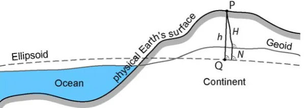
Ellipsoidal heights (h) can be converted into orthometric heights (H) by applying the geoid undulation (N), also known as geoid-ellipsoid separation, geoid height (not to be confused with the height above geoid, i.e. the orthometric height) or N value:
H = h – N
[image:9.595.150.450.524.631.2]Equation 7 Strictly speaking, this equation is an approximation since h and N are measured along the ellipsoid normal, while H is measured along the curved plumbline, i.e. the direction of the gravity vector (Figure 3).
The angle between the direction of the gravity vector and the ellipsoid normal at a surface point is known as the deflection of the vertical. Since this angle only amounts to several seconds of arc, its effect on equation (7) can be ignored in practice (Featherstone, 2007). It is essential that the N value refers to the correct reference ellipsoid. Across Australia, the AUSGeoid98 (Featherstone et al., 2001) provides a regularly spaced grid of geoid undulations relative to the GRS80 ellipsoid, while a new model is currently being generated (Featherstone et al., 2007). Numerous models have been produced to supply users with the necessary geoid undulations in other parts of the world (e.g. Featherstone and Olliver, 2001; Iliffe et al., 2003; Denker et al., 2008; NGA, 2008), and transformation software for vertical datums is readily available, e.g. in Australia (GA, 2007), the U.S. (Mulcare, 2004b; NGS, 2004b; NOAA, 2008) and Europe (BKG, 2006; OS, 2008). In a GIS context, this transformation needs to be performed before the data are imported into the GIS if it is desired to create from GPS-derived positions a digital elevation model (DEM) that has a physical meaning. Therefore, in practice, geoid undulation information plays two crucial roles (Rizos, 1997): On the one hand, N values are needed to convert (non-GPS) geodetic control information (i.e. orthometric heights) into a mathematically equivalent reference system to which GPS results refer (i.e. ellipsoidal heights). On the other hand, we require N values to obtain orthometric heights (i.e. physical meaning) from GPS-derived ellipsoidal heights (i.e. geometrical meaning), which is referred to as GPS levelling or GPS heighting.
8.2 Datum Transformation using Geoid Undulations In many countries, spatial professionals continue to face the task of transforming coordinates from an older datum in form of projected grid coordinates, based on a regional (i.e. non-geocentric) ellipsoid, and gravity-related heights (e.g. E, N, H in the AMG66/84) to curvilinear coordinates in a newer datum that is based on a geocentric ellipsoid (e.g. φ,
λ, h in the GDA94), e.g. in order to combine older terrestrial survey control information with recent GPS observations. The orthometric height H is independent of the reference ellipsoid. However, this transformation requires knowledge of the appropriate N value referring to the regional ellipsoid (i.e. Nreg). It can be performed as follows:
- Convert (E, N)reg to (φ, λ)reg on the regional
ellipsoid using Redfearn’s (1948) formulae. - Convert H to hreg using equation (7) and Nreg (if
known).
- Convert the curvilinear coordinates (φ, λ, h)reg to
Cartesian coordinates (X, Y, Z)reg using equation
(2) and the regional ellipsoid parameters. - Perform a similarity transformation between the
regional datum (X, Y, Z)reg and the geocentric
datum (X, Y, Z)geo according to equation (5).
- Convert the Cartesian coordinates (X, Y, Z)geo in
the geocentric datum to curvilinear coordinates (φ, λ, h)geo, e.g. using equation (4).
However, we may not have access to the required geoid undulations Nreg referring to the regional
ellipsoid. Readily available geopotential models generally only supply N values related to the geocentric ellipsoid (i.e. Ngeo). This problem can be
overcome by making use of the fact that the difference in ellipsoidal height is equivalent to the change in geoid undulation between the datums (ignoring rotations and scale change):
hreg = H + Nreg and hgeo = H + Ngeo
Equation 8 Since H is independent of the reference ellipsoid and therefore constant, differencing yields:
Δhgeo-reg = ΔNgeo-reg
Equation 9 If, in the procedure outlined above, step 2 is skipped and an initial ellipsoidal height of hreg = 0 is used in
step 3, the result after step 5 represents the difference in ellipsoidal height Δhgeo-reg between the
two ellipsoids. A geopotential model such as the AUSGeoid98 can then be used to obtain Ngeo and
thus Nreg is determined based on equation (9). The
final coordinates in the geocentric datum are obtained by performing step 2 and repeating steps 3-5 with the correct hreg value. It should be noted that
a more rigorous treatment of the problem is required if rotations and scale change between the datums cannot be ignored, cf. Kotsakis (2008).
9 Concluding Remarks
absence of geoid undulations referenced to a regional ellipsoid has been presented. It is hoped that this paper has eliminated any confusion in regards to geodetic transformations applicable to GIS users. In practice, most of these transformations can be performed within the GIS environment or with readily available software. However, users need to ensure that the correct transformation parameters are applied.
References
Altamimi, Z., and Boucher, C., 2002, The ITRS and ETRS89 Relationship: New Results from ITRF2000. In EUREF Publication No. 10, edited by J. Torres and H. Hornik (Frankfurt: Verlag des Bundesamtes für Kartographie und Geodäsie), 49-52.
Altamimi, Z., Collilieux, X., Legrand, J., Garayt, B., and Boucher, C., 2007, ITRF2005: A New Release of the International Terrestrial Reference Frame Based on Time Series of Station Positions and Earth Orientation Parameters. Journal of Geophysical Research, 112, B09401, doi: 10.1029/2007JB004949. Baker, L. S., 1974, Geodetic Networks in the United
States. Canadian Surveyor, 28, 445-451.
BKG, 2006, Quasigeoid of the Federal Republic of Germany GCG05, http://www.bkg.bund.de (accessed 9 Nov 2009).
Bock, Y., 1998, Reference Systems. In GPS for Geodesy, edited by P. J. G. Teunissen and A. Kleusberg (Berlin: Springer), 1-42.
Bomford, A. G., 1967, The Geodetic Adjustment of Australia 1963-1966. Survey Review, 19, 52-71. Boucher, C., and Altamimi, Z., 1992, The EUREF
Terrestrial Reference System and its First Realizations. Veröffentlichungen der Bayerischen Kommission für die Internationale Erdmessung, Heft 52, München, 205-213. Bowring, B. R., 1985, The Accuracy of Geodetic
Latitude and Height Equations. Survey Review, 28, 202-206.
Bugayevskiy, L. M., and Snyder, J. P., 1995, Map Projections: A Reference Manual (London: Taylor and Francis).
Collier, P., 2002, Development of Australia’s National GDA94 Transformation Grids. Consultant’s Report to the Intergovernmental Committee on Surveying and Mapping, University of Melbourne, Australia.
Craymer, M. R., 2006, The Evolution of NAD83 in Canada. Geomatica, 60, 151-164.
CRS, 2008, Information and Service System for European Coordinate Reference Systems,
http://crs.bkg.bund.de/crs-eu (accessed 9 Nov 2009).
Dawson, J., and Steed, J., 2004, International Terrestrial Reference Frame (ITRF) to GDA94
coordinate transformations, http://www.ga.gov.au/image_cache/GA3795.pdf
(accessed 9 Nov 2009).
Denker, H., Barriot, J.-P., Barzaghi, R., Fairhead, D., Forsberg, R., Ihde, J., Kenyeres, A., Marti, U., Sarrailh, M., and Tziavos, I. N., 2008, The Development of the European Gravimetric Geoid Model EGG07. In Observing Our Changing Earth, IAG Symp. Vol. 133, edited by M.G. Sideris (Berlin: Springer), 177-185. EUREF, 2008, Reference Frame Sub Commission
for Europe, http://www.euref.eu/ (accessed 9 Nov 2009).
Featherstone, W. E., 2002, Attempts to Unify the Australian Height Datum between the Mainland and Tasmania. In Vertical Reference Systems, edited by P. Drewes, A. Dodson, L. P. Fortes, L. Sanchez, and P. Sandoval (Berlin: Springer), 328-333.
Featherstone, W. E., 2007, Absolute and Relative Testing of Gravimetric Geoid Models using Global Positioning System and Orthometric Height Data. Computers & Geosciences, 27, 807-814.
Featherstone, W. E., Claessens, S. J., Kuhn, M., Kirby, J. F., Sproule, D. M., Darbeheshti, N., and Awange, J. L., 2007, Progress Towards the New Australian Geoid-Type Model as a Replacement for AUSGeoid98. Proceedings of SSC2007, Hobart, Tasmania, edited by V. Janssen and M. Russell, 243-261.
Featherstone, W. E., Kirby, J. F., Kearsley, A. H. W., Gilliland, J. R., Johnston, G. M., Steed, J., Forsberg, R., and Sideris, M. G., 2001, The AUSGeoid98 Geoid Model for Australia: Data Treatment, Computations and Comparisons with GPS-levelling Data. Journal of Geodesy, 75, 313-330.
Featherstone, W. E., and Kuhn, M., 2006, Height Systems and Vertical Datums: A Review in the Australian Context. Journal of Spatial Science, 51, 21-42.
Featherstone, W. E., and Olliver, J. G., 2001, A Review of Geoid Models over the British Isles: Progress and Proposals. Survey Review, 36, 78-100.
GA, 2007, AUSGeoid98, http://www.ga.gov.au/ geodesy/ausgeoid/ (accessed 9 Nov 2009). Grafarend, E. W., and Krumm, F. W., 2006, Map
Projections: Cartographic Information Systems (Berlin: Springer).
Harvey, B. R., 1986, Transformation of 3D Co-ordinates. The Australian Surveyor, 33, 105-125. Hofmann-Wellenhof, B., Lichtenegger, H., and
Collins, J., 2001, GPS: Theory and Practice, 5th edition (Wien: Springer).
ICSM, 2002, Geocentric Datum of Australia Technical Manual, Version 2.2., http://www.icsm.gov.au/icsm/gda/gdatm/index.h tml (accessed 9 Nov 2009).
IERS, 2008, ITRF Transformation Parameters, http://itrf.ensg.ign.fr/trans_para.php (accessed 9 Nov 2009).
Ihde, J., and Augath, W., 2002, The European Vertical Reference System (EVRS), its Relation to a World Height System and to the ITRS. In Vistas for Geodesy in the New Millennium, IAG Symp. Vol. 125, edited by J. Adam and K.-P. Schwarz (Berlin: Springer), 78-83.
Iliffe, J., and Lott, R., 2008, Datums and Map Projections for Remote Sensing, GIS and Surveying, 2nd edition (Dunbeath: Whittles Publishing).
Iliffe, J., Ziebart, M., Cross, P. A., Forsberg, R., Strykowski, G., and Tscherning, C. C., 2003, OSGM02: A New Model for Converting GPS-derived Heights to Local Height Datums in Great Britain and Ireland. Survey Review, 37, 276-293.
Kinneen, R. W., and Featherstone, W. E., 2004, Empirical Evaluation of Published Transformation Parameters from the Australian Geodetic Datums (AGD66 and AGD84) to the Geocentric Datum of Australia (GDA94). Journal of Spatial Science, 49, 1-31.
Kotsakis, C., 2008, Transforming Ellipsoidal Heights and Geoid Undulations between Different Geodetic Reference Frames. Journal of Geodesy, 82, 249-260.
LPMA, 2008, DatumTran Software, http://www. lpma.nsw.gov.au/survey_maps/geodesy/gda/ datumtran_software (accessed 9 Nov 2009). Maling, D. H., 1993, Coordinate Systems and Map
Projections, 2nd edition (Oxford: Pergamon Press).
Malys, S., and Slater, J., 1994, Maintenance and Enhancement of the World Geodetic System 1984. Proceedings of ION GPS-94, Salt Lake City, UT, 17-24.
Malys, S., Slater, J. A., Smith, R. W., Kunz, L. E., and Kenyon, S. C., 1997, Refinements to the
World Geodetic System 1984. Proceedings of ION GPS-97, Kansas City, MO, 841-850. Merrigan, M. J., Swift, E. R., Wong, R. F., and
Saffel, J. T., 2002, A Refinement to the World Geodetic System 1984 Reference Frame. Proceedings of ION GPS 2002, Portland, OR, 1519-1529.
Morgan, P. J., 1992, An Analysis of the Australian Height Datum: 1971. The Australian Surveyor, 37, 46-63.
Mulcare, D. M., 2004a, NGS Toolkit, Part 8: The National Geodetic Survey NADCON Tool. Professional Surveyor, 24(2), 28-30 & 32.
Mulcare, D. M., 2004b, NGS Toolkit, Part 9: The National Geodetic Survey VERTCON Tool. Professional Surveyor, 24(3), 46&48.
NGA, 2008, Earth Gravitational Model 2008 (EGM2008), http://earth-info.nga.mil/GandG/ wgs84/gravitymod/egm2008/ (accessed 9 Nov 2009).
NGS, 2004a, NADCON: North American Datum Conversion Utility, http://www.ngs.noaa.gov/ PC_PROD/NADCON/ (accessed 9 Nov 2009). NGS, 2004b, VERTCON: North American Vertical
Datum Conversion Utility, http://www.ngs.noaa. gov/PC_PROD/VERTCON/ (accessed 9 Nov 2009).
Nievinski, F. G., and Santos, M. C., 2007, An Analysis of Errors Introduced by the Use of Transformation Grids. In Dynamic Planet, IAG Symp. Vol. 130, edited by P. Tregoning and C. Rizos (Berlin: Springer), 677-684.
NIMA, 2004, Department of Defense World Geodetic System 1984: Its Definition and Relationships with Local Geodetic Systems. NIMA Technical Report TR8350.2.
NOAA, 2008, Vertical Datum Transformation: Integrating America’s Elevation Data, http://vdatum.noaa.gov/ (accessed 9 Nov 2009). OS, 2008, Ordnance Survey Coordinate
Transformer, http://gps.ordnancesurvey.co.uk/ convert.asp (accessed 9 Nov 2009).
Poder, K., and Hornik, H., 1989, The European Datum 1987 (ED87). IAG RETrig Publication No. 18 (München: International Association of Geodesy).
Pollard, J., 2002, Iterative Vector Methods for Computing Geodetic Latitude and Height from Rectangular Coordinates. Journal of Geodesy, 76, 36-40.
Redfearn, J. C. B., 1948, Transverse Mercator Formulae. Empire Survey Review, 69, 318-322. Rizos, C., 1997, Principles and Practice of GPS
Roelse, A., Granger, H. W., and Graham, J. W., 1971, The Adjustment of the Australian Levelling Survey 1970-1971. Technical Report 12, Canberra, Division of National Mapping. Schwarz, C. R., and Wade, E. B., 1990, The North
American Datum 1983: Project Methodology and Execution. Bulletin Géodésique, 64, 28-62. Seeger, H., 1994, EUREF: The New European
Reference Datum and its Relationship to WGS84. Proceedings of FIG XX Int. Congress, Melbourne, Australia, paper TS506.4.
Seemkooei, A. A., 2002, Comparison of Different Algorithms to Transform Geocentric to Geodetic Coordinates. Survey Review, 36, 627-633. Snyder, J. P., 1987, Map Projections – A Working
Manual, USGS Professional Paper 1395 (Washington: U.S. Government Printing Office). Soler, T., 1998, A Compendium of Transformation
Formulas useful in GPS Work. Journal of Geodesy, 72, 482-490.
Soler, T., and Marshall, J., 2003, A Note on Frame Transformations with Applications to Geodetic Datums. GPS Solutions, 7, 23-32.
Swift, E., 1994, Improved WGS84 Coordinates for the DMA and Air Force GPS Tracking Sites. Proceedings of ION GPS-94, Salt Lake City, UT, 285-292.
Torge, W., 2001, Geodesy, 3rd edition (Berlin: de Gruyter).
True, S.A., 2004, Planning the Future of the World Geodetic System 1984. Proceedings of IEEE PLANS 2004, Monterey, CA, 639-468.
Vaniček, P., and Krakiwsky, E. J., 1986, Geodesy: The Concepts, 2nd edition (Amsterdam: North Holland).
Vorhauer, M. L., 2007, National Readjustment of 2007. The American Surveyor, 4(4), 48-52. Zilkoski, D. B., Richards, J. H., and Young, G. M.,
1992, Results of the General Adjustment of the North American Vertical Datum of 1988. Surveying and Land Information Systems, 52, 133-149.
Author Posting. © Geoinformatics International, 2009.