FAKULTI KEJURUTERAAN ELEKTRIK UNIVERSITI TEKNIKAL MALAYSIA MELAKA
DEVELOPMENT OF A POINT-TO-POINT (PTP) POSITIONING CONTROLLER FOR A ROBOTIC HAND
Yeo Chin Kiat
" I hereby declare that I have read through this report entitle " Development of a Point-to-Point Positioning Controller for a Robotic Hand" and found that it has comply the partial fulfillment for awarding the degree of Bachelor of Mechatronics Engineering "
Signature : ...
Supervisor's Name : ...
DEVELOPMENT OF A POINT-TO-POINT (PTP) POSITIONING CONTROLLER FOR A ROBOTIC HAND
YEO CHIN KIAT
A report submitted in partial fulfillment of the requirements for the degree
of Bachelor of Mechatronics Engineering
Faculty of Electrical Engineering
UNIVERSITI TEKNIKAL MALAYSIA MELAKA
" I declare that this report entitle " Development of a Point-to-Point Positioning Controller for a Robotic Hand" is the result of my own research except as cited in the references. The report has not been accepted for any degree and is not concurrently submitted in candidature of any other degree "
Signature : ...
Name : ...
ACKNOWLEDGEMENT
The work of this thesis represents the concerted efforts of the individual over almost a year. One of the features of training is collaboration and certainly it required many acts of collaboration by the company people in order to come to completion.
When I first started my work , it was quite hard to adapt to the environment but as time passed, I were able to adapt myself to all the condition. After some time, I begin to say that how blessed I felt that the topic and contents of my work was fascinating and enjoyable to me even after many hours of study, processing information, and working. I am also grateful that the knowledge gained through this training is so relevant and useful to my current teaching practices.
So, I would like to express my deepest appreciation to those who provided me their support and expertise to me for the past few months. First of all, I begin my thanks to my supervisor, Dr. Mariam binti Md Ghazaly for guiding me all the way and giving me some idea on how to accomplish my work while giving me knowledge on the engineering field. Furthermore, I would also like to thanks to my family and my friends who shows their support on me in order for the completion of this thesis.
ABSTRACT
ABSTRAK
TABLE OF CONTENTS
CHAPTER TITLE PAGE
ACKNOWLEDGEMENT i
ABSTRACT ii
ABSTRAK iii
TABLE OF CONTENTS iv
LIST OF TABLES vii
LIST OF FIGURES ix
LIST OF APPENDICES xiv
LIST OF SYMBOLS xv
LIST OF ABBREVIATIONS xvi
1 INTRODUCTION 1
1..1 General Overview 1
1.2 Motivation 2
1.3 Problem Statement 5
1.4 Objectives 6
1.5 Scope of Project 6
1.6 Project Overview 7
2 LITERATURE REVIEW 8
2.1 Overview of Underactuated Robotic Hand and Point-to-Point Positioning System
8
2.2 Motion Control of Robotic Hand 14 2.3 Actuator of the Robotic Hand 15 2.4 Robotic Hand Control Technique 17 2.4.1 Proportional-Integral-Derivative (PID)
Controller
18
CHAPTER TITLE PAGE 2.4.1.2 Trial and Error Tuning Method 20 2.4.2 Artificial Intelligent Controller 21 2.4.3 Nominal Characteristic Trajectory Following
(NCTF) Controller
22
2.5 Micro-Box 24
2.6 Summary 25
3 METHODOLOGY 26
3.1 Introduction 26
3.2 Project Development 28
3.3 System Overview of Robotic Hand System 32 3.4 Micro-Box Connection and Wiring Layout 32 3.5 Robotic Hand Experimental Setup 33 3.6 Calibration of Encoder for DC Geared Motor 36 3.7 Development of Open Loop System 36 3.8 System Identification Tools 38 3.9 Development of Closed Loop System 40 3.9.1 Development of Uncompensated Closed
Loop System
40
3.9.2 Design of Proportional-Integral-Derivative (PID) Controller
41
3.9.3 Tracking Control with PID Controller 44
3.10 Summary 45
4 RESULTS AND DISCUSSION 46
4.1 Calibration of DC Geared Motor Encoder Gain 46 4.2 Open Loop Characteristic for Robotic Hand 50 4.2.1 Open Loop Test of Robotic Hand 50 4.2.2 Characteristic Equation of Robotic Hand 53 4.2.3 Effect of Open Loop System to Robotic
Finger
CHAPTER TITLE PAGE
4.3 Uncompensated Closed-Loop Performance 63 4.4 Closed-Loop System with PID Controller 70 4.4.1 Ziegler-Nichols Tuning Method 71 4.4.2 Trial and Error Tuning Method 75 4.4.3 Performance of PID Controller on
Point-to-Point Positioning Controller
79
4.4.4 Performance of PID Controller on Tracking Controller
86
4.4.4.1 Sine Wave Signal with Frequency of 0.1Hz
86
4.4.4.2 Sine Wave Signal with Frequency of 0.5Hz
88
4.4.4.3 Sine Wave Signal with Frequency of 1.0Hz
90
4.4.4.4 Sine Wave Signal with Frequency of 1.5Hz
92
4.4.4.5 Sine Wave Signal with Frequency of 2.0Hz
94
4.4.4.6 Triangular Input Signal 96 4.4.4.7 Stepwise Input Signal 98
4.5 Summary 99
5 CONCLUSION AND RECOMMENDATION 101
5.1 Conclusion 101
5.2 Recommendation 103
REFERENCES 104
LIST OF TABLES
TABLE TITLE PAGE
1.1 Most Injured Body Parts 2013 4
2.1 The Comparison Between Wire Driven Underactuated Robotic Hand, Underactuated Robotic Hand and Traditional Robotic Hand.
13
2.2 The Comparison between the Characteristic of DC Geared Motor, Servo Motor and Stepper Motor.
17
2.3 The Effect of PID Controller Parameters to the System Performance.
19
3.1 The Gantt Chart for the Projek Sarjana Muda 1 30 3.2 The Gantt Chart for the Projek Sarjana Muda 2 31 3.3 The Ziegler-Nichols Tuning Rule Based on Ultimate Gain
and Ultimate Period.
44
4.1 The Angle of Encoder for DC Geared Motor 48 4.2 The Angle on Protractor for DC Geared Motor 49 4.3 The Angle Of The DC Geared Motor With Difference Input
Voltage
51
4.4 The Characteristic Equation for the Robotic Hand. 54 4.5 The Average Output Angle For The Encoder and Protractor
At The DC Geared Motor and The Angle of Elevation of The Finger.
62
4.6 The Uncompensated Closed Loop Performance of the Robotic Hand for 15 °.
64
4.7 The Uncompensated Closed Loop Performance of the Robotic Hand for 30 °.
65
4.8 The Uncompensated Closed Loop Performance of the Robotic Hand for 45 °.
TABLE TITLE PAGE 4.9 The Uncompensated Closed Loop Performance of the
Robotic Hand for 60 °.
67
4.10 The Uncompensated Closed Loop Performance of the Robotic Hand for 75 °.
68
4.11 The Uncompensated Closed Loop Performance of the Robotic Hand for 90 °.
69
4.12 Performance of Robotic Hand Kp = 289.8. 75 4.13 Performance of Robotic Hand Kp = 289.8 and Ki = 3.5. 76 4.14 Performance of Robotic Hand Kp = 289.8 and Kd = 5. 77 4.15 Comparison between the Robotic Hand Performance with
Derivative Gain Tuned.
78
4.16 Performance of Robotic Hand with PID Controller for Experimental.
83
4.17 Performance of Robotic Hand with PID Controller for Simulation.
83
4.18 Comparison between the Performance of Uncompensated and Compensated Closed-Loop System with PID Controller.
83
4.19 The Relationship between Base Reference Angle and Finger 5 Fingertip to Robotic Hand Palm Angle.
85
4.20 Comparison of Performance of Uncompensated Closed-Loop System with PID Controller.
LIST OF FIGURES
FIGURE TITLE PAGE
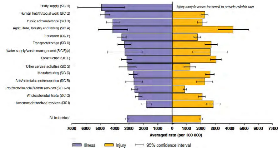
1.1 Estimated Rates of Total Cases of Self-Reported Work-Related Illness and Non-Fatal Injury by Industry 2013 in Great Britain.
3
2.1 The 2-DOF Underactuated iHY Hand. 9
2.2 The 12-DOF UT Hand I 10
2.3 The Baxter Easyhand Underactuated Robotic Hand Prototype. 10
2.4 The Underactuated RBO Hand 11
2.5 The Underactuated Colombia Hand 11
2.6 The SARAH Hand 12
2.7 The iHY Hand Underactuated Hand Design. 15 2.8 The Block Diagram of the Fuzzy Logic Controller . 21 2.9 The Structure of the Fuzzy Logic Controller. 22 2.10 The Structure of the Nominal Characteristic Trajectory
Following (NCTF) controller.
23
2.11 Micro-Box. 24
3.1 Flowchart For Point-to-Point Positioning System Robotic Hand Design.
29
3.2 The System Overview of Robotic Hand by Using the Micro-Box.
32
3.3 The Driver Board Connection. 33
3.4 Top View of Robotic Hand. 34
3.5 Side View of Robotic Hand. 34
3.6 Angle of Rotation of the DC Geared Motor with Protractor 1. 35 3.7 Angle Between the Fingertip and the Palm of the Robotic
Hand with Protractor 2.
35
3.8 The String Connect To The Coupling. 36
3.9 The Block Diagram of the Open Loop System for Robotic Hand.
FIGURE TITLE PAGE 3.10 The Open Loop System Model Block Diagram. 37 3.11 Real Time Simulation and Experimental Block Diagram. 38
3.12 System Identification Tools. 39
3.13 The Block Diagram of the Uncompensated Closed Loop System for the Robotic Hand.
40
3.14 The Uncompensated Closed Loop System. 41 3.15 The Block Diagram of the Compensated Closed System with
PID Controller for Robotic Hand.
41
3.16 Compensated Closed Loop System With PID Controller Using Matlab Simulink
42
3.17 The Flow Chart For Designing The Proportional-Integral-Derivative Controller.
43
3.18 Tracking Control for the PID Controller in Matlab Simulink. 45 4.1 The Output Angle of DC Geared Motor Encoder With Input of
1V.
47
4.2 The Output Angle of DC Geared Motor Encoder With Input of 10V.
47
4.3 Comparison the Angle of Encoder and Protractor Reading with Error.
49
4.4 The Changes of the Input Voltage with Respect to the Output Angle and Standard Deviation.
52
4.5 Experimental and Simulation Output Model for Transfer Function 1.
54
4.6 Experimental and Simulation Output Model for Transfer Function 2.
55
4.7 Experimental and Simulation Output Model for Transfer Function 3.
55
4.8 Experimental and Simulation Output Model for Transfer Function 4.
56
4.9 Experimental and Simulation Output Model for Transfer Function 5.
FIGURE TITLE PAGE
4.10 Experimental and Simulation Output Model for Transfer Function 6.
57
4.11 Experimental and Simulation Output Model for Transfer Function 7.
57
4.12 Experimental and Simulation Output Model for Transfer Function 8.
58
4.13 Experimental and Simulation Output Model for Transfer Function 9.
58
4.14 Experimental and Simulation Output Model for Transfer Function 10.
59
4.15 Graph of Error Against Time for Transfer Function 1 to Transfer Function 5.
59
4.16 Graph of Error Against Time for Transfer Function 6 to Transfer Function 10.
60
4.17 The Relationship Between the DC Geared Motor Encoder and Protractor with the Angle of Elevation of the Finger.
61
4.18 The Performance of the Robotic Hand for 15° of Reference Angle.
64
4.19 The Performance of the Robotic Hand for 30° of Reference Angle.
65
4.20 The Performance of the Robotic Hand for 45° of Reference Angle.
66
4.21 The Performance of the Robotic Hand for 60° of Reference Angle.
67
4.22 The Performance of the Robotic Hand for 75° of Reference Angle.
68
4.23 The Performance of the Robotic Hand for 90° of Reference Angle.
69
4.24 The Ziegler-Nichols Tuning Method with Gain, K=482. 71 4.25 The Ziegler-Nichols Tuning Method for Gain, K = 482 Zoom
View for Angle.
72
FIGURE TITLE PAGE 4.27 The Ziegler-Nichols Tuning Method for Gain, K = 483 Zoom
View for Angle.
73
4.28 The Ziegler-Nichols Tuning Method for Gain, K = 484. 73 4.29 The Ziegler-Nichols Tuning Method for Gain, K = 484 Zoom
View for Angle.
74
4.30 The Robotic Hand Performance with P Controller. 75 4.31 The Robotic Hand Performance with PI Controller. 76 4.32 The Performance Robotic Hand with PD Controller. 77 4.33 Performance of Robotic Hand with PID Controller for 15° of
Reference Angle.
80
4.34 Performance of Robotic Hand with PID Controller for 30° of Reference Angle.
80
4.35 Performance of Robotic Hand with PID Controller for 45° of Reference Angle.
81
4.36 Performance of Robotic Hand with PID Controller for 60° of Reference Angle.
81
4.37 Performance of Robotic Hand with PID Controller for 75° of Reference Angle.
82
4.38 Performance of Robotic Hand with PID Controller for 90° of Reference Angle.
82
4.39 The Relationship between Base Reference Angle and Finger 5 Fingertip to Robotic Hand Palm Angle.
85
4.40 Performance of Tracking Control with Sine Wave Signal for 15° at 0.1 Hz.
87
4.41 Performance of Tracking Control with Sine Wave Signal for 30° at 0.1 Hz.
87
4.42 Performance of Tracking Control with Sine Wave Signal for 45° at 0.1 Hz.
88
4.43 Performance of Tracking Control with Sine Wave Signal for 15° at 0.5 Hz.
89
4.44 Performance of Tracking Control with Sine Wave Signal for 30° at 0.5 Hz.
FIGURE TITLE PAGE 4.45 Performance of Tracking Control with Sine Wave Signal for
45° at 0.5 Hz.
90
4.46 Performance of Tracking Control with Sine Wave Signal for 15° at 1.0 Hz.
91
4.47 Performance of Tracking Control with Sine Wave Signal for 30° at 1.0 Hz.
91
4.48 Performance of Tracking Control with Sine Wave Signal for 45° at 1.0 Hz.
92
4.49 Performance of Tracking Control with Sine Wave Signal for 15° at 1.5 Hz.
93
4.50 Performance of Tracking Control with Sine Wave Signal for 30° at 1.5 Hz.
93
4.51 Performance of Tracking Control with Sine Wave Signal for 45° at 1.5 Hz.
94
4.52 Performance of Tracking Control with Sine Wave Signal for 15° at 2.0 Hz.
95
4.53 Performance of Tracking Control with Sine Wave Signal for 30° at 2.0 Hz.
95
4.54 Performance of Tracking Control with Sine Wave Signal for 45° at 2.0 Hz.
96
4.55 Comparison of Performance for PID Controller with Triangular Input Signal for 15° at 0.5Hz and 1.0Hz.
97
4.56 Comparison of Performance for PID Controller with Triangular Input Signal for 30° at 0.5Hz and 1.0Hz.
97
4.57 Comparison of Performance for PID Controller with Triangular Input Signal for 45° at 0.5Hz and 1.0Hz
98
LIST OF APPENDICES
APPENDIX TITLE PAGE
A DC Geared Motor SPG30-300K with Encoder Specification 110 B Matlab Simulink Block Diagram for Control System of
Underctuated Robotic Hand
LIST OF SYMBOLS
V - Voltage
ᵒ - Degree
θ - Angle
e - error
s - second
LIST OF ABBREVIATIONS
DOF - Degree of Freedom
SISO - Single-Input-Single-Output
PID - Proportional-Integral-Derivative
PTP - Point-to-Point
DC - Direct Current
PWM - Pulse Width Modulation
NCTF - Nominal Characteristic Trajectory Following
NCT - Nominal Characteristic Trajectory
FLC - Fuzzy Logic Controller
GUI - Graphical User Interface
CHAPTER 1
INTRODUCTION
1.1 General Overview
Robotic hand is a kind of mechanical hand that had similar functions as a human hands which using either an actuator or string mechanism to obtain the force to provide the motion, action and position. Nowadays, most of the robotic design are depend heavily on the automatic control system to control and monitor the operation of the robots. The using of the automatic control system on the robotic designs and robotic hands will reduce the humans workload due to their repeatability, high accuracy and able to operate continuously without humans control. Furthermore, the robotic hands also can be useful where the robotic hands can replace human hands in the dangerous working situation or as a auxiliary for delicate work such as a surgical operation.
Generally, the simplest robotic hands having two degree of freedom (2-DOF) and for the most complex robotic hands can be more than over 30-DOF when high accuracy and precision of the position is needed. A degree of freedom will be formed when there is a joint occurred. In order to design a finger for robotic hands, each finger should had three degree of freedom (3-DOF) so that the finger of the robotic hands had the minimum requirement to mimic the ability and motion of the human hands. Then, the angle and position of the finger will be change by increasing or decreasing the output voltage to the actuator.
system performance on the finger of the robotic hands are examined and compare the system performance of the robotic hands.
1.2 Motivation
In recent years, the human like skills robotic hands have attracted the attention from the people around the world for replacing the human hand which require the high precision with fast response. The robotic hand can be used not only for the industrial sector, but it also can be implemented in the medical sector and manufacturing sector. Furthermore, the robotic hand also play an important roles in term of healthcare where the aging population and the people who lost their hand may need the service such prosthetic hand to make their daily life more convenience.
Figure 1.1 : Estimated Rates of Total Cases of Self-Reported Work-Related Illness and Non-Fatal Injury by Industry 2013 in Great Britain [1].