DEVELOPMENT OF TRACKING SYSTEM USING W I D
HAZRULLIZAM
BIN
IDRIS
This report is submitted in partial fulfillment of requirement for the award of Bachelor of Electronic Engineering (Computer Engineering) with honours
Faculty of Electronic and Computer Engineering Universiti Teknikal Malaysia Melaka
UNlVERSTl TEKNIKAL MALAYSIA MELAKA
sc
- FAKULTI KEJURUTERAAN ELEKTRONIK DAN KEJLJRUTERAAN KOMPlJTERYI
I-
.- r, BORANG PENGESAHAN STATUS LAPORAN
'"&n
--
PROJEK SARJANA MUDA IITajuk Projek DEVELOPMENT OF TRACKING SYSTEM LJSING RFID Sesi
Pengajian : 2007 / 2008
I
Saya : HAZRULLIZAM BIN IDRISmengaku membenarkan Laporan Projek Sarjana Muda ini disimpan di Perpustakaan
'
dengan syarat-syarat kegunaan seperti berikut:
1 . Laporan adalah hakmilik Universiti Teknikal Malaysia Melaka.
2. Perpustakaan dibenarkan membuat salinan untuk tujuan pengajian sahaja.
3. Perpustakaan dibenarkan membuat salinan laporan ini sebagai bahan pertukaran antara institusi pengajian tinggi.
4. Sila tandakan ( d ) : 5.
SULIT*
(Mengandungi maklumat yang berdarjah keselamatan atau kepentingan Malaysia seperti yang termaktub di dalam AKTA RAHSIA RASMl 1972) (Mengandungi maklumat terhad yang telah
TERHAD* ditentukan oleh organisasilbadan di mana
penyelidikan dijalankan)
TlDAK TERHAD
(TANDATANGAN PENULIS)
Alamat Tetap: PO. BOX. 999
89808, BEAU FORT
SABAH
MOHAMAD ZO!NOL ABlDlN B ABD AZ!K
Po7 :>'d~2.?
Fak-!ti EIplr.tror.:k ?a:. K e Y.0-p-te: (FKEKK).
cr.i~/e:s:'.i TpPn:l:a' Ma:a;rs:a Me'aka ;'JT2M) Kar,:g Wrk-zcl :XO. Aye: Keroh 73450 Meiaka
DECLARATION
"I hereby declare that this report is result of my own effort except for quotes that have been cited clearly in the references."
Name : Hazrullizam Bin Idris
SUPERVISOR APPROVAL
"I hereby declare that I have read this report and in my opinion this report is sufficient in terms of scope and quality for the award of Bachelor of Electronic Engineering
(Computer Engineering) with honours."
Signature :
*
Supervisor : ~ o h d i o i i o l Abidin B. Abd Aziz
ABSTRACT
Radio Frequency Identification (RFID) is coming, and it's bringing a streamlined
revolution. When dealing with the tracking device, Radio Frequency Identification
(RFID) is the latest phase in the decades-old trend of the miniaturization of computers
that can be used as an efficient tracker. The development of tracking system using the
Radio Frequency Identification (RFID) technology is quite new but something that
promising. The idea is to use the RFID reader as a check point to provide the coordinate
reference as the RFID transponder will act a transmitter or traced object. The tracking
system actually based on external database system that will provide the recorded
information about the reader. Since the reader detected by the database, then the tracking
system will process the data and will show the result of subject tracking. A synchronize
combination between RFID reader, database and the tracking system will come out as an
efficient tracker. The tracking system was developed using Microsoft Visual Basic (VB)
that offered graphical user interface (GUI) application. The visual graphic interface
provide the graphical mapping that show the result of tracking. The visual graphical
interface development is more on software programming syntax coding. The another
part of the system is the database. The database is handled by SQL database. MySQL
database software was used to construct the database for the whole tracking system. The
purpose of this database is to be the reference of any related stored data and
information. The system is standalone which is communicated with external database
handler. The tracking system only will interact directly to the database and show the
ABSTRAK
Radio Frequency Identification (RFID) telah muncul dan ianya telah membawa rovolusi
jalur aliran. Apabila berbincang tentang peranti penjejak, Radio Frequency Identification
(RFID) merupakan fasa terkini dalam gaya lama pengecilan saiz computer yang boleh
digunakan sebagai peranti penjejak yang efisien. Pembangunan sistem penjejak
menggunakan teknologi Radio Frequency Identification (RFID) adalah sedikit baru
tetapi menjanjikan masa depan yang h a s . Ideanya adalah dengan menggunakan
pembaca RFID sebagai titik periksa untuk meneydiakan koordinat rujukan dan
penghantar isyarat RFID akan bertindak sebagai pemancar atau objek jejakan. Sistem ini
sebenarnya berdasarkan sistem pangkalan data luaran yang akan menyediakan informasi
ynag dirakam tentang pemabaca. Apabila pembaca dikesan oleh pangkalan data, system
penjejak akan memproses data tersebut dan menunjukkan hasil lokasi subjek jejakan.
Kombinasi yang selaras antara Pembaca RFID, pangkalan data dan sistem penjejak akan
menghasilkan penjejak yang efisien. Sistem ini bertindak sendirian yang mana akan
berkomunikasi dengan pengendali pangkalan data luaran. Sistem penjejak ini akan
berinteraksi kepada pangkalan data dan menunjukkan keputusan yang diterima daripada
pengendali pangkalan data luaran. Sistem ini dibangunkan dengan menggunakan
Microsoft Visual Basic (VB) yang menawarkan aplikasi antara muka pengguna grafik.
Antaramuka visual grafik menyediakan pemetaan grafik yang memaparkan hasil
jejakan. Pembangunan antaramuka visual grafik ini lebih kepada pengekodan sintaks
perisian pengaturcaraan. Bahagian lain dalam sistem ini adalah pangkalan data.
Pangkalan data ini dijalankan oleh pangkalan data SQL. Perisian pangkalan data
MySQL digunakan untuk membina keseluruhan pangkalan data bagi keseluruhan
sistem. Tujuan pangkalan data ini adalah untuk menjadi rujukan bagi setiap simpanan
TABLE OF CONTENT
CHAPTER TITLE PAGE
PROJECT TITLE VERIFICATION FORM DECLARATION SUPERVISOR APPROVAL DEDICATION ABSTRACT ABSTRAK CONTENT LIST OF TABLE LIST OF FIGURE
LIST OF ABREVIATION LIST OF APPENDIX
I INTRODUCTION
1.1 PROJECT BACKGROUND
1.2 OBJECTIVES
1.3 SCOPE OF WORKS
1.4 PROBLEM STATEMENT
i ii iii iv v vi vii viii xi xii xiv xv
I1 LITERATURE REVIEW 4
2.1 INTRODUCTION 4
2.2 LITERATURE REVIEW OF RFID 4
2.2.1 Radio Frequency Identification Technology 4
2.2.2 Radio Frequency Identification System 6
CHAPTER TITLE PAGE
2.2.4 Radio Frequency Identification Architecture
2.2.5 Host and Software System
2.3 DATABASE SERVER TECHNOLOGY
2.3.1 Overview of Database
2.3.2 Introduction to MySQL
2.3.3 Advantages of Using MySQL
2.3.4 MySQL as a Relational Database
2.3.6 Relational Operation Model for MySQL
2.4 RFID AND PROGRAMMING SOFTWARE
2.4.1 RFID Study Kit
2.4.2 Microsoft Visual Basic 2005 (VB.NET)
I11 SYSTEM SOFTWARE DEVELOPMENT 32
3.1 INTRODUCTION 3 2
3.2 VISUAL GRAPHICAL INTERFACE DEVELOPMENT 33
3.3 SOFTWARE PROGRAMMING SYNTAX CODING 4 1
3.4 DATABASE DEVELOPMENT PROCESS 45
IV RESULTS, DISCUSSION AND ANALYSIS
4.1 INTRODUCTION
4.2 SYSTEM VISUAL GRAPHIC DISPLAY
4.2.1 System Tracing Coordinate
4.2.2 The real System Application
CHAPTER TITLE
V CONCLUSION AND FUTURE WORK
5.1 CONCLUSION
5.2 FUTURE DEVELOPMENT
REFERENCES
APPENDIX A APPENDIX
R
APPENDIX C
LIST OF TABLE
NO. TITLE
2.1 3ALogic RFID Specification
2.2 Mifare RFID Specification
2.3 FKEKK list of stuff details
LIST OF FIGURE
NO.
TITLEA Schematic of Power and Data Flow in a UHF RFID System
Active RFID System
Passive RFID System
Sample of RFID Tags
RFID reader
Example of software System
Official MySQL Logo
3ALogics RFID Study Kit
Mifare RFID
Visual Basic The Start Page
Visual Basic Grouped windows
The Solution Explorer with two projects
Project process flowchart
System Interface Description by User
System Interface Description by Location
Interface Development Script (a)
System Log History Interface Description by User
Interface Development Script (b)
System Log History Interface Description by Location
Interface Development Script (c)
Programming based on visual scripting
Software Development Script
Programming based on code scripting
Database Handler Flowchart
NO.
TITLEFlowchart for Record Set Module Design
Programming to Add New data
Programming to Edit data
Programming to Delete data
Programming to compile data
FKEKK administration and academic building (Front View)
FKEKK administration and academic building (Ground Level)
FKEKK administration and academic building (Level One)
FKEKK administration and academic building (Level Two)
FKEKK administration and academic building (Level Three)
Floor Mapping (situation 1)
Floor Mapping (situation 2)
Floor Mapping (situation 3)
Graphical User Interface (a)
Graphical User Interface (b)
Graphical User Interface (c)
Display format for System interface
LIST OF ABREVIATION ANSI API CODSYL DBMS EPC HF IBM ID ISM band
I S 0
JDBC LF MHz ODBC ODMG
PHP
RDBMS RFID SQL UHF UNIX VB.NetAmerican National Standards Institute
Application Programming Interface
Conference on Data Systems Languages
Database Management System
Electronic Product Code
High Frequency
International Business Machines Corporation
Identification
Industrial, Scientific and Medical radio bands
International Organization for Standardization
Java Database Connectivity
Low Frequency
Megahertz
Open Database Connectivity
Object Data Management Group
Hypertext Preprocessor
Relational Database Management System
Radio Frequency Identification
Structured Query Language
Ultra High Frequency
Computer operating system
LIST OF APPENDIX
APPENDIX TITLE PAGE
A Full Programming Source Code in Visual Basic 66
B
MFR Application Programming Interface (API) Library 87CHAPTER I
INTRODUCTION
1.1 PROJECT BACKGROUND
Radio frequency (RF) technology is used in many different applications, such as
television, radio, cellular phones, radar, and automatic identification systems. RFID
stands for radio frequency identification and describes the use of radio frequency signals
to provide automatic identification. Unlike the electronic article surveillance (EAS)
Systems used for theft detection, RFID provides a unique serial number for
identification of an object. RFID technology was invented in 1948, but it was not
commercialized until the 1980s. One of its first known applications was during World
War 11, when it was used by the British radar system to differentiate between friendly
and enemy aircraft with attached radio transponders.
Radio Frequency Identification (RFID) is an automatic identification method,
relying on storing and remotely retrieving data using devices called RFID tags or
transponders. An RFID tag is an object that can be attached to or incorporated into a
product, animal, or person for the purpose of identification using radio waves.
The main theme of this project is relying on the application of the Radio
Frequency Identification (RFID) based on RFID tag as an identification medium. The
project will provide a tracking system using a location mapping orientation. The result
will be displayed on a map oriented interfaces which is communicate with the RFID
reader as a checked point. The idea is using a RFID cards are also known as "proximity"
RFID cards will contain an identity (ID) reference number and data, which means each
personal identity fixed with one identity (ID) to represent that person in the system for
the purpose.
1.2 OBJECTIVES
The main objective of this project is to develop the tracking system using Radio
Frequency Identification (RFID) application technology. The main idea is to develop
application software on tracking system using Radio Frequency Identification (RFID)
application technology. The system will be in the form of software and using the RFID
technology as an external tracking hardware. The system will communicate to the
hardware tracking component and manage the tracking activity. To provide a user
friendly system, a graphical user interface (GUI) will be prepared to display the result of
tracking activity in a graphical mapping format. Graphical user interface (GUI) will
make the system can be manage easier and suitable for all level of literacy. Besides of
easy handling the graphical mapping also create a systematic control and monitoring
environment for the tracking system supervisor.
Finally, the internal database should be provided to make a complete dynamic
system which can trace a real time condition and also keep the history of the previous
activity that happened. The combination of these objectives will be fulfill and achieves
with one perfectly organized system call 'The Tracking System Using RFID' as my
project to be develop.
1.3 SCOPE OF WORKS
The purpose of an RFID system is to enable data to be transmitted by a mobile
device, called a tag, which is read by an RFID reader and processed according to the
needs of a particular application. Related to this project the application of a tracking
system will be controlled by application software. The scope of this project is to develop
the application software in a graphical user interface (GUI) form to control, manage and
data transmitted by a RFID reader. Between reader and the software will be another
database component. This software will process a data from the outside main database
component. This system not only will visualize the real time result but the whole system
activities will be recorded in an appropriate data form to represent the activities log. The
software will do this task and application reading database, display location and storing
data.
1.4 PROBLEM STATEMENT
In thc matter of controlling and monitoring the most important aspect is how to trace the
track of any activities that happened. For example in the high alert territory such as
military area, prison or any kind of place in needs of privacy, every single activity
should be aware and under supervised. This aspect of monitoring is important to prevent
any undesirable activity and faulty. Nowadays the experts in the field of security come
with a solution on how to monitor and control such activity by using a CCTV. So every
single action will be captured by the camera and stored as an image. The problem is how
the system will be supervised when dealing with a large area and capacity. It means the
supervisor should recognize each and every single faces in the area involved and jotted
down what they had done and where it was.
On this kind of difficulty and problem, a complete and efficient system should be
provided which is considering all the matters occur compare to others method. So the
answer to overcome this problcm is to provide a tracking system that can trace the track
of identity in the supervised territory. In term of tracking, the system will identify any
movement and activity by tracing the track of every person such as a detail on where are
they now, where they headed, where they had been. So no more lost trace phenomenon
CHAPTER I1
LITERATURE REVIEW
2.1 INTRODUCTION
In order to execute this project, literature review must be done to comprehend the
whole system and to decide the best inputs, outputs and used devices. From literature
review, there will be an analysis regarding the advantages and disadvantages for each
phase of this project. Equipment data sheets and manuals provided information such as
dimension, operation and specification of the RFID reader also will discussed. There are
two main parts which is review on RFID and review on Database that wrap up the main
title 'Development of tracking system using RFID'.
2.2 LITERATURE REVIEW OF W I D
2.2.1 Radio Frequency Identification (RFID) Technology
Radio frequency (RF) technology is used in many different applications, such as
television, radio, cellular phones, radar, and automatic identification systems. RFID
stands for radio frequency identification and describes the use of radio frequency signals
to provide automatic identification [I]. Unlike the electronic article surveillance (EAS)
Systems used for theft detection, RFID provides a unique serial number for
identification of an object [2]. RFID is used in the Mobil Speed pass system to pay for
gas without going into the store, in automobile immobilizer systems to prevent theft by
uniquely identifying a key with an embedded chip, in Fast Lane and E-Z Pass toll road
systems to automatically pay tolls without stopping, in animal identification, in secure
pallets, cases, and items. RFID technology was invented in 1948, but it was not
commercialized until the 1980s. One of its first known applications was during World
War 11, when it was used by the British radar system to differentiate between friendly
and enemy aircraft with attached radio transponders [3].
Most media accounts of RFID are actually about one form of RFID, the
electronic product code (EPC) system [2]. Initially, RFID was being used to identify objects in the MIT robotics laboratory but was found to be useful for managing the
supply chain. The electronic product code (EPC) was developed by the Auto-ID Center
at MIT and is now being managed by EPCglobal Inc. EPCglobal Inc. is a global not-for-
profit standards organization commercializing the Electronic Product CodeTM (EPC) and
RFID worldwide. It is one important form of RFID used by retailers to manage the
supply chain. EPC has standardized chip designs and protocols to enable the mass
production of low-cost passive RFID tags in the 860-960 MHz range. EPC is a
technology similar to the uniform product code (UPC) barcode identification used to
provide information about the product to which the EPC tag is attached except that it can
be read at a distance and does not require line-of-sight aiming like the barcode system
[21
The advantage of RFID is that it does not require direct contact or line-of-sight
scanning. An RFID system consists of three components: an antenna and transceiver
which often combined into one reader and a transponder that usually the tag. The
antenna uses RF waves to transmit a signal that activates the transponder. When
activated, the tag transmits data back to the antenna. The data is used to notify a
programmable logic controller that an action should occur. The action could be as
simple as raising an access gate or as complicated as interfacing with a database to carry
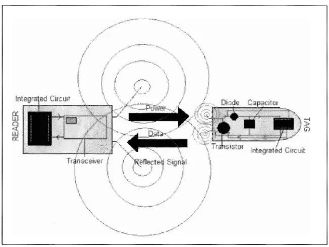
Figure 2.1: A Schematic of Power and Data Flow in a UHF RFID System.
The Figure 2.1 shows a typical RFID tag consists of a microchip attached to a
radio antenna mounted on a substrate. The chip can store as much as 2 kilobytes of data
[3]. For example, information about a product or shipment, date of manufacture,
destination and sell by date can be written to a tag. In order to retrieve the data stored on
an RFID tag, a reader is needed. A typical reader is a device that has one or more
antennas that emit radio waves and receive signals back from the tag. The reader then
passes the information in digital form to a computer system [4].
2.2.2 Radio Frequency Identification (RFID) System
An RFID system may consist of several components: tags, tag readers, edge
servers, middleware, and application software. The purpose of an RFID system is to
enable data to be transmitted by a mobile device, called a tag, which is read by an RFID
reader and processed according to the needs of a particular application. The data
transmitted by the tag may provide identification or location information, or specifics
about the product tagged, such as price, color, date of purchase, etc [4]. The use of RFID
[image:21.540.112.438.92.337.2]or unfriendly ("identify friend or foe" (IFF). RFlD quickly gained attention because of
its ability to track moving objects. As the technology is refined, more pervasive and
possibly invasive uses for RFID tags are in the works [ 5 ] .
In a typical RFID system, individual objects are equipped with a small,
inexpensive tag. The tag contains a transponder with a digital memory chip that is given
a unique electronic product code. The interrogator, an antenna packaged with a
transceiver and decoder, emits a signal activating the RFID tag so it can read and write
data to it. When an RFID tag passes through the electromagnetic zone, it detects the
reader's activation signal. The reader decodes the data encoded in the tag's integrated
circuit (silicon chip) and the data is passed to the host computer. The application
software on the host processes the data, often employing Physical Markup Language
(PML)
P I .
Take the example of books in a library. Security gates can detect whether or not
a book has been properly checked out of the library. When users return items, the
security bit is re-set and the item record in the integrated library system is automatically
updated. In some RFID solutions, a return receipt can be generated. At this point,
materials can be roughly sorted into bins by the return equipment. Inventory wands
provide a finer detail of sorting. This tool can be used to put books into shelf-ready order
PI.
2.2.3 Types of Radio Frequency Identification (RFID)
The main component of RFID technology is the transponderltag
,
which in mostcases comprises of a chip and antenna mounted onto a substrate or an enclosure. The
chip consists of a processor, memory and radio transmitter. These transponders
communicate via radio frequency to a reader, which has its own antennas. The readers
can interface through wired or wireless medium to a main computer. Transponders are
also known as smart or radio tags. The memory will vary, depending on the
Transponders can either be Read Only (RJO) which are pre-programmed with a
unique identification or they can be Read Write (RIW) for applications that require data
to be stored in the transponder and can be updated dynamically. Another form of
transponder is Write Once Read Many times (WORM). This will allow for an
identification number to be written to the transponder once. The information is stored in
the memory, it cannot be changed but the transponder can be read many times.[l] The
two most common types of RFID technologies are Active and Passive. Active RFID
transponders are self powered and tend to be more expensive than Passive. Having
power on board allows the tag to have greater communication distance and usually
larger memory capacity 141.
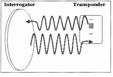
(a) Active W I D Systems
Active tags are used on large assets, such as cargo containers, rail cars and large
reusable containers, which need to be tracked over long distances such as in a
distribution yard, for example [4]. They usually operate at 455 MHz, 2.45 GHz, or 5.8
[image:23.532.156.383.466.622.2]GHz, and they typically have a read range of 60 feet to 300 feet (20 meters to 100 meters) [3].
Figure 2.2: Active RFID System
There are two types of active tags which is a transponders and a beacons. Active
transponders are woken up when they receive a signal from a reader. These are used in
transponder approaches a tollbooth, a reader at the booth sends out a signal that wakes
up the transponder on the car windshield. The transponder then broadcasts its unique ID
to the reader. Transponders conserved battery life by having the tag broadcast its signal
only when it is within range of a reader [ 5 ] .
Beacons are used in most real-time locating systems (RTLS), where the precise
location of an asset needs to be tracked. In an RTLS, a beacon emits a signal with its
unique identifier at pre-set intervals which it could be every three seconds or once a day,
depending on how important it is to know the location of an asset at a particular moment
in time. The beacon's signal is picked up by at least three reader antennas positioned
around the perimeter of the area where assets are being tracked [ 5 ] .
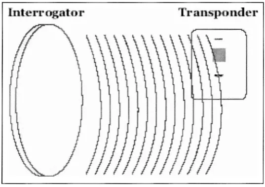
(b) Passive W I D Systems
Passive RFID tags have no power source and no transmitter. They are cheaper
than active tag and require no maintenance, which is why retailers and manufacturers are
looking to use passive tags in their supply chains [ 5 ] . They have a much shorter read
[image:24.532.133.402.478.667.2]range than active tags which is a few inches to 30 feet.