i WIRELESS INTELLIGENCE HOME SECURITY INTEGRATED WITH
GLOBAL SYSTEM FOR MOBILE (GSM)
MOHD AMI BIN AHMAD LAWI
This report is submitted partial fulfillment of the requirement for the award of Bachelor of Electronic Industry Engineering with Honours
Faculty of Electronic and Computer Engineering
Universiti Teknikal Malaysia Melaka (UTeM)
ii
UNIVERSTI TEKNIKAL MALAYSIA MELAKA
FAKULTI KEJURUTERAAN ELEKTRONIK DAN KEJURUTERAAN KOMPUTER
BORANG PENGESAHAN STATUS LAPORAN
PROJEK SARJANA MUDA II
Tajuk Projek : Wireless Intelligence Home Security Integrated with Global
System for Mobile (GSM) Sesi Pengajian : 2011/2012
Saya MOHD AMI BIN AHMAD LAWI mengaku membenarkan Laporan Projek Sarjana Muda ini disimpan di Perpustakaan dengan syarat-syarat kegunaan seperti berikut:
1. Laporan adalah hakmilik Universiti Teknikal Malaysia Melaka.
2. Perpustakaan dibenarkan membuat salinan untuk tujuan pengajian sahaja.
3. Perpustakaan dibenarkan membuat salinan laporan ini sebagai bahan pertukaran antara institusi pengajian tinggi.
4. Sila tandakan ( √ ) :
SULIT* (Mengandungi maklumat yang berdarjah keselamatan atau kepentingan Malaysia seperti yang termaktub di dalam AKTA RAHSIA RASMI 1972)
TERHAD* (Mengandungi maklumat terhad yang telah ditentukan oleh organisasi/badan di mana penyelidikan dijalankan)
TIDAK TERHAD
Disahkan oleh:
__________________________ ___________________________________
(TANDATANGAN PENULIS) (COP DAN TANDATANGAN PENYELIA)
Alamat Tetap: Lot 563,Jln Masjid, Wakaf Che Yeh, 15100, Kota Bharu Kelantan.
iii
“I hereby declare that this report is the result of my own work except for quotes as cited in the references.”
Signature : ……….
Author : MOHD AMI BIN AHMAD LAWI
iv
“I hereby declare that I have read this report and in my opinion this report is sufficient in term of the scope and quality for the award of bachelor of Electronic
Engineering (Industrial Electronics) With Honours.”
Signature : ………
Supervisor’s Name : Pn. Nur Fatihah binti Azmi
v
vi
ACKNOWLEDGEMENT
Alhamdulillah, all praise to Allah the Most Beneficent and the Most Merciful, who
has taught what I knew not. It is the grace of the Almighty Allah that this research work has been completed successfully on time.
First and foremost, I would like to take this opportunity to thank my project supervisor, Pn. Nur Fatihah binti Azmi for this invaluable guidance, assistance and support throughout the project. Under her supervision, many aspects regarding on this project has been explored and with the knowledge, idea and support received from him, this thesis can be presented in the time given. For all lecturer involved in teaching my course, thanks for the lesson that been delivered.
vii
ABSTRACT
viii
ABSTRAK
ix
TABLE OF CONTENT
CHAPTER TITLE PAGE
DEDICATION i
ACKNOWLEGMENT ii
ABSTRACT iii
ABSTRAK iv
TABLE OF CONTENTS ix-xi
LIST OF FIGURE xii
I INTRODUCTION 1
1.1 Introduction 1
1.2 Problem Statement 2
1.3 Objectives of project 2
1.4 Project Scopes 3
1.5 Significant of the project 4
1.6 Project methodology 4
1.6.1 Determine the title. 4 1.6.2 Make research for the circuit will be involed. 4 1.6.3 Get component for each sub system. 4 1.6.4 Testing the component for each sub system 5 1.6.5 Testing circuit for each sub system 5 1.6.6 Integrated circuit for each sub system 5 1.6.7 Evaluation of the system 5
x
II LITERATURE REVIEW 6
2.1 Introduction 6
2.2 Microcontroller circuit 7
2.3 Components and equipment 7 2.3.1 SK40C Circuit 7 2.3.2 Global System for Mobile (GSM) 8 2.3.3 Microprocessor 16F877A 10 2.3.4 RF Transmitter Modules (433MHz) 12 2.3.5 RF Receiver Modules (433MHz) 13 2.3.6 IR LED emits infrared. 15
III METHODOLOGY 17
3.1 Introduction 17
3.2 Methodology Operation 18
3.2.1 Title Selection 19
3.2.2 Discussion with the Lecturer about the Title 19 3.2.3 Data Collection Method 19 3.2.4 Analysis about the circuit and the component 19 3.2.5 Print the circuit on PCB 20
3.2.6 Etching Circuit 20
3.2.7 Drilling Process 21
3.2.8 Drill 22
3.2.9 Installation the component 22
3.2.10 Circuit Testing 22
3.2.11 Soldering Process 22
3.2.12 Steps to solder the component 23 3.2.13 Equipment on Soldering Steps 24 3.2.15 Software design concept 25
3.3 Project Planning 31
xi
IV RESULT AND DISCUSSION 34
4.1 OPERATING SYSTEM 34
4.1.1 Operating Environment 34
4.1.2 Block diagram of project operation 35
4.1.3 GSM Technology 36
4.1.4 GSM provided SMS 37
4.2 Circuit result 39
4.3 AT commands 43
V CONCLUSION AND SUGGESTION 46
5.1 Conclusion 46
5.2 Suggestion and Future development 47
VI REFERENCES 50
xii
LIST OF FIGURE
FIGURE TITLE PAGE
Figure 2.1 Example of SK40C circuit. 8 Figure 2.2 Schematic for interfacing the SK40C with a GSM modem 9 Figure 2.3 Components for GSM to enable the function 9
Figure 2.4 A microcontroller based system 10
Figure 2.5 (a) The physical appearance of the programmable 11 IC for PIC 16F877A, (b) the USB ICSP PIC programmer
Figure 2.6 RF transmitter module circuit 13
Figure 2.7 RF transmitter module 13
Figure 2.8 RF receiver module circuit 14
Figure 2.9 RF receiver module 14
Figure 2.10 The transmitted signal between two IR sensors. 15 Figure 2.11 Two packages IR sensor (3mm or 5mm). 15
Figure 3.1 Flow chart Methodology 18
Figure 3.2 Coding design flowchart 25
Figure 3.3 CCS compilers for PIC 26
Figure 3.4 CCS compiler progress 26
Figure 3.5 PICkit 2 start-up program 27
Figure 3.6 PICkit 2 Import Hex 28
Figure 3.7 Burn the program to the PIC 28
Figure 3.8 Toolbars illustrates 30
Figure 3.9 Create schematic and save 30
Figure 3.10 Flow chart how the alarm functions 32 Figure 4.1 Wireless Intelligence home security integrated with GSM model 34
xiii
Figure 4.3 GSM Architecture 36
Figure 4.4 Tested picture microcontroller 39
Figure 4.5 Tested circuit microcontroller 40
Figure 4.6 Using DB9 to make connection 40
Figure 4.7 Simulation circuit 41
xiv
LIST OF TABLE
TABLE TITLE PAGE
Table 2.1 RF transmitter module specifications 12 Table 2.2 RF receiver module specifications 14
Table 3.1 Gantt chart 31
1
CHAPTER I
INTRODUCTION
1.1 Introduction
This project Wireless Intelligence Home Security Integrated with Global System for Mobile (GSM) was build to make sure that our residences is a safe place. This wireless burglars alarm was a wireless system which is the sensor and the control unit was connect without using wire. Besides that, this project was focus on microcontroller PIC16f877A.
2
1.2 Problem statement
As we can see today, most people still use man power on safety of their house. This project is an invention and a way to make human life become easier which is they can save their time and man power. These following are the problems are occurred and the reasons why people need this alarm.
Every house has an alarm, but when the intruders entered the house just a bell that rang. Owner never knows what happen to their house when they not home. To overcome this problem, Global System for Mobile (GSM) have been used, it will send short message to the phone saying that your house have been invaded.
It also use wireless tool that connect all the equipment. The intruders won‟t know where alarm been installed. It also can save a lot of wire to be use around the house to attach sensor and we also can cut the budget.
1.3 Objectives of Project
The objectives of this project are:
I. To design a wireless intelligence home security integrated with Global System for Mobile (GSM) that will inform owner about their house conditions.
II. To facilitate sensor to detect intruders by using wireless network control.
3
1.4 Project Scope
For this project it focuses more for residence use. This Wireless Intelligence Home Security Integrated with Global System for Mobile (GSM) was focus on microcontroller PIC16f877A. Function of microcontroller is to control the input signal and then it will process the input to give a correct output at that time. Meanwhile, these wireless systems communicate using a radio frequency (RF) signal between sensor circuit and control unit. It also will send message to mobile phone using Global System for Mobile (GSM).
1.4.1 System design using Xbee
We need transmitter and a receiver. The receiver must be connected to Peripheral Interface Controller (PIC) and for the transmitter circuit must be connected with sensor.
1.4.2 Controller Circuit using PIC
Design and development of the system controller using Peripheral Interface Controller (PIC). Microcontroller that I used is PIC16f877A.
1.4. 3 Deployment
Buy Global System for Mobile (GSM) and assembled it with Peripheral Interface Controller (PIC) circuit.
1.4.4 Sensor
4
1.5 Significant Of The Project
The significant of the Wireless Intelligence Home Security Integrated with Global System for Mobile (GSM) is:
i. By installing this device it can keep our residence safe. ii. It also can alert owner when the strangers entered.
iii. Besides that, it also could decrease violence and potential threat to family members.
iv. Developments of the project that will reduce the symptoms of burglary in the resident without affecting the daily life of comfort and quality of consumer.
1.6 Project methodology
In this part, I have several main things to finish my project which are project planning, literature review and expected part of the project.
1.6.1 Determine the title.
Determine project topic that going to be made. Surf internet to find the additional data.
1.6.2 Make research for the circuit will be involed.
Read project book or circuit that project topic was being chosen.
Make the analysis with all the circuit and equipment involed such as, wireless part, electronic circuit part and model part.
1.6.3 Get component for each sub system
Make sure all components in the project circuit available in market.
5
1.6.4 Testing the component for each sub system
Test every component whether in good condition or not. If not should have replace or get new one from the store.
1.6.5 Testing circuit for each sub system
Purpose of testing circuit would be to ensure circuit can function nicely. If there is problem should troubleshoot the circuit and detect the problem.
1.6.6 Integrated circuit for each sub system Purpose of integrated circuit.
1.6.7 Evaluation of the system
Test all the circuit of the system and test the all the functionality of the project.
1.6.8 Expected Result
Testing of final assembly circuit in operation, application records the results. Presentation of the project.
6
CHAPTER II
LITERATURE REVIEW
2.1 Introduction
The idea for project wireless burglar alarm combine with Global System for Mobile (GSM) was build to make sure that our residences is a safe place. After seeing so many house get broke in it make me thinking about this alarm. Therefore, I have do some research on several books of the electronic circuit books, websites, eBooks and journals from the internet. After that, I start to plan the work on how to integrate the circuits in this project.
7
2.2 Microcontroller circuit
Control circuit is the most important part in this project, it is to make sure that the project can be function well as the planned. In this project, I have chosen some control circuit such as, Microcontroller. All of this control circuit are use to make sure that the circuit can operate and perform well in future.
2.3 Components and equipment
The most important components are electronic components that will appliance in an electronic circuit. Components or circuit findings are create and defined by performance characteristics of a component. Components are produced with its owned functions and operated in accordance with the resolution made. The components that will use in this project are the microcontroller, sk40c circuit, Global System for Mobile (GSM), and etc. There are also a variety of tools used such as soldering iron, suckers, and others.
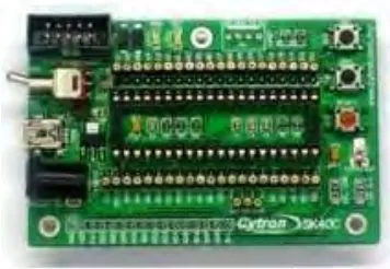
2.3.1 SK40C Circuit
SK40C is another enhanced version of 40 pins PIC microcontroller start up kit. It is designed to offer an easy-to-start solution for PIC MCU user. Users are able to utilize the function of PIC by directly plugging in the I/O components in whatever way that is convenient to them. With UIC00B connector on board, user can start developing projects and have fun with this kit right away. This kit comes without PIC microcontroller to provide the freedom for user to choose PIC model [10].
8
Figure 2.1: Example of SK40C circuit.
2.3.2 Global System for Mobile (GSM)
GSM modem is specialized type of modem that operates over subscription based wireless networks which is similar to a mobile phone. A GSM modem accepts a SIM card, and basically acts like a mobile phone for the computer. Traditional modem is attached to computers for „dial-up‟ to connect with other computer systems. A GSM modem operates in a similar fashion, except that it sends and receives data through radio waves rather than a telephone line.
Besides the dial-up connection, GSM modem can also be used for sending and receiving SMS which is also one of the key features of GSM modem[4]. In this issue, we discuss on how to set up a simple home automation where we can control and monitor the alarm status by using SMS. Some of the features of this GSM Modem are as follow:
RS-232 Interface
Tri-Band: GSM900, GSM1800 and GSM1900 Support TCP/IP
Support standard extended open AT commands Support GPRS class 10
9
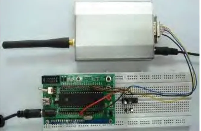
[image:23.612.168.488.186.407.2]In this project, I also use the SK40C together with PIC16F877A as the main controller. I also need to short the DSR and DTR, and also the CTS and RTS, those are pin required for hand-shaking. Without shorting these pairs of pin, the system might not work as expected. This main controller is connected to the GSM modem via a MAX232 circuit as shown in the schematic below.
Figure 2.2: Schematic for interfacing the SK40C with a GSM modem
[image:23.612.162.495.462.679.2]10
2.3.3 Microprocessor PIC16F877A
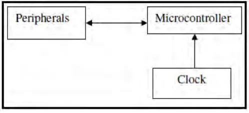
[image:24.612.221.470.319.432.2]A microcontroller is a stripped-down version of the very same architecture, with all the important features placed on one chip. The same system as the previous figure using a microcontroller looks like Figure 2. The microcontroller based system requires no additional circuitry except a clock input and it can, many cases, directly drive peripheral outputs. The difference between the microprocessor and the microcontroller arises because of their different end-usage. The microcontroller that will be investigated is the PIC16F877, which is at the upper end of the mid-range series of the microcontrollers developed by MicroChip Inc. It is characterized by RISC architecture instead of the CISC architecture used, for example, by the Motorola 6809.
Figure 2.4: A microcontroller based system