Theoretical modeling of the effect of plasticity on reverse
transformation in superelastic shape memory alloys
Wenyi Yan*
1, Chun Hui Wang
2, Xin Ping Zhang
1and Yiu-Wing Mai
1
1
Centre for Advanced Materials Technology,
School of Aerospace, Mechanical and Mechatronic Engineering,
The University of Sydney, NSW 2006, Australia
2
Aeronautical and Maritime Research Laboratory,
Defence Science and Technology Organisation,
506 Lorimer Street, Fishermans Bend, VIC 3207, Australia
Keywords: Phase transformations; Plasticity; Shape memory alloys; Theory and modeling; Constitutive
equations
Abstract
Stimulated by recent experimental results on superelastic NiTi shape memory alloy, a theoretical study is
carried out to quantify the effect of plasticity on stress-induced martensite transformation, using a
constitutive model that combines phase transformation and plasticity. A constraint equation is introduced to
quantify the phenomenon of the stabilization of plasticity on stress-induced martensite. The stabilized
martensite volume fraction is determined by the equivalent plastic strain. The transformation constitutive
model is adopted from a generalized plastic model with Drucker-Prager type phase transformation functions,
which are pressure sensitive, while the plasticity is described by the von Mises isotropic hardening model.
The martensite volume fraction is chosen as the internal variable to represent the transformation state and it
is determined by the consistency transformation condition. An approach to calibrate model parameters from
uniaxial tensile tests is explored, as well as the issue of elastic mismatch between austenite and martensite is
discussed. Based on the proposed constitutive model, the influence of hydrostatic stress on transformation is
examined. As an example of application, this new constitutive model is employed to numerically study the
transformation field and the plastic deformation field near a crack tip.
1. Introduction
It is well known that shape memory alloys exhibit not only shape memory effect but also superelastic
deformation behavior. At a certain high temperature, shape memory alloy under external loading can display
extraordinarily large deformation, up to strains of several percents. This large amount of deformation can
“elastically” recover completely after unloading. This abnormal superelastic phenomenon is due to the
intrinsic stress-induced austenite-to-martensite forward transformation and martensite-to-austensite reverse
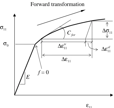
transformation during a loading-unloading process. The transformation deformation mechanism is
schematically illustrated in Fig. 1. The initial austenite phase can be transformed into martensite phase under
occurs during the phase transformation process, which leads to significant macroscopic deformation. Once
the transformed material is unloaded, the unstable martensite phase will transform backward to the stable
austenite recovering the transformation strain.
The superelastic deformation behaviour in shape memory alloys has been exploited to develop smart and
functional structures in many fields [1-3]. Of particular importance is its exciting application in the field of
biomedical engineering. For example, superelastic NiTi vascular stents have been developed to reinforce
blood vessels. Comparing to traditional stainless steel stents, these superelastic stents have enhanced
recoverable strain so that they can be easily deployed to constricted arteries and the risk of stent failure
would be greatly reduced [4, 5]. In addition, further potential applications of shape memory alloys are being
investigated, such as shape memory alloys-based functional composites. Recent reports, e.g., [6], suggest
that shape memory alloy NiTi has super resistance against wear due to its superelasic deformation and could
be applied in tribological engineering.
Although shape memory alloy NiTi has found many important applications, especially in biomedical
engineering, little information on the failure of this material existed in the literature. McKelvey and Ritchie
[7, 8] carried out a series of experimental study on the growth of fatigue cracks in NiTi alloy. With regarding
to the constitutive behaviors of this material, they have experimentally found that plastic deformation after
forward transformation could stabilize martensite and hinder the reverse transformation. Eventually, reverse
transformation can be suppressed completely with a certain amount of plastic deformation. They have also
reported that austenite-to-martensite forward transformation did not occur at the crack tip of a superelastic
NiTi. The inhibition of the transformation was believed to be due to the high hydrostatic tensile stress near
the tip of at a fatigue crack. Because the austenite-to-martensite transformation in NiTi involves a negative
volume change, the high hydrostatic tensile stress might prevent such transformation from happening.
Stimulated by the experimental investigation of McKelvey and Ritchie [7, 8] on superealstic NiTi, the
deformation, especially the effect of plastic deformation on the stabilization of martensite so that it can be
applied to theoretically study the failure of superelastic shape memory alloys. Many constitutive models for
transformation in shape memory alloys have been published [2, 9]. Transformation thermomechanical
theory, crystallographic theory of martensitic transformation and/or micromechanics approach have been
applied to develop some of these models [10-13]. For the purpose of our present research, a
phenomenological model developed by Auricchio et al. [14] and Lubliner and Auricchio [15] was modified
to describe forward and reverse transformation in superelastic shape memory alloys. Without detailing the
evolution process of the material microstructure, this model can phenomenologically quantify the
macroscopic deformation due to transformation. And, this model was successfully applied to numerically
simulate the deformation of NiTi stents recently by Rebelo et al. [16]. In contrast to many other models, this
phenomenological model has also considered the volume change during transformation process. Thus, it can
be used to study the influence of hydrostatic stress on transformation. The von Mises isotropic hardening
theory is adapted directly to describe the plastic deformation happening in the martensite phase after the
forward transformation. The stabilized martensite volume fraction is proposed as a function of the equivalent
plastic strain. Therefore, the constraint of the plastic deformation on the reverse transformation can be
quantified.
The structure of this paper is as follows. The combined constitutive model is detailed in Section 2, where the
evolution functions of the martensite volume fraction are derived based on the consistency conditions.
Thereafter, the transformation strain rate is determined. For the sake of completeness, the equation to
determine the plastic strain rate is also given in Section 2. A simple linear relationship is proposed between
the stabilized martensite volume fraction and the equivalent plastic strain. Methods of calibrating the
material parameters from uniaxial tensile tests are outlined in Section 3. Based on the present model, the
effect of hydrostatic stress on transformation has been discussed. This constitutive model has been
implemented as a material subroutine in the finite element package ABAQUS [17] to assist the analysis of
Finally, as an example of application, the transformation field and the plastic field near the crack tip of a
superelasitc NiTi shape memory alloy is examined in Section 4.
2. Constitutive model
Under external loading condition, the total strain rate of a superelastic material generally composes of three
parts:
pl tr el + +
= (1)
where el is elastic strain rate due to elastic deformation, tr transformation strain rate due to transformation and pl plastic strain rate due to dislocation movement. Plastic deformation due to dislocation movement is unrecoverable, whereas elastic and transformation strains are recoverable. During unloading process, reverse
transformation from martensite to austenite can occur in the superelastic regime, which partly or fully
recovers the deformation due to the forward transformation from austenite to martensite. Here, only
mechanical loading condition for transformation is considered and the forward and reverse transformation is
treated as an isothermal process. These constraints could be removed by introducing relevant
temperature-dependent parameters. Because plastic yield strength is normally higher than the transformation stress in
shape memory alloys, unlike transformation-induced plasticity in steels, transformation and plastic
deformation will not occur simultaneously for shape memory alloy. The following details a combined
constitutive model that describes both the transformation strain and plastic strain.
In the present work, both austenite and martensite are considered to be elastic isotropic. The elastic strain
rate el is related to the stress rate via the isotropic Hooke’s law:
: M
=
el
, (2)
where M is the elastic isotropic flexibility tensor of the fourth-order and is the stress rate tensor. It is
further assumed that austenite and martensite have identical elastic properties (Young’s modulus and
martensite and the austenite is negligibly small. By contrast, for binary NiTi shape memory alloys the
Young’s modulus of the martensite is about one-third to one half of the Young’s modulus of the austenite
[18]. Normally, the transformation strain rate is much larger than the elastic strain rate during a
transformation process, either forward transformation or reverse transformation. The elastic mismatch
between austenite and martensite can only affect the macroscopic deformation very limitedly even for NiTi
shape memory alloys. While this difference can be readily incorporated in the theoretical model, the
resulting model may require more elaborate experiments to identify the material constants; this will be
discussed in detail in the next section.
2.1 Transformation model
To avoid the complexity of tracking the detailed evolution of the material microstructure during phase
transformations, a phenomenological approach will be adopted to describe the forward and reverse
transformation in superelastic shape memory alloys. Such an approach is most appropriate for
polycrystalline shape memory alloys with very fine grains, such as NiTi used in stent device. Here the model
developed by Auricchio et al [14] and Lubliner and Auricchio [15] is modified in a consistent manner to
account for multiaxial stresses. The martensite volume fraction rate will be determined from a
self-consistency condition, rather than assuming an empirical relation in [14,15].
Choosing the martensite volume fraction f as an internal state variable, which varies between zero and unity.
The potential functions for forward and reverse transformations are a Drucker-Prager type, i.e.
) ( 3
) ,
( f Y f
Ffor =σeq + ασm − for , for forward transformation (3a) )
( 3
) ,
( f Y f
Frev =σeq + ασm − rev , for reverse transformation (3b)
where s:s
2 3
=
σeq is the von Mises equivalent stress, s is the deviatoric stress tensor, and σm is the
) ( 3 1 tr m =
σ and s= −σmI (4)
where I is the second-order unit tensor. The function Yfor( f) and Yrev( f) denote the transformation hardening functions to be determined later. Generally, these hardening functions also depend on temperature.
Here, investigation is focused on a given temperature, at which material demonstrates superelastic behavior.
The influence of the hydrostatic stress on transformation is manifested by the term ασm in Eq. (3). The parameter α is a material constant, which is relative to the transformation volume strain as discussed later.
In the case of α=0, the transformation function degenerate to the von Mises type.
During phase transformation the potentials Ffor(σσσσ, f) and Frev(σσσσ,f) remain zero. It will prove advantageous to define an equivalent transformation stress σtreq as
m eq
tr
eq =σ + ασ
σ 3 . (5)
Then the conditions for transformation can be simply expressed as,
) ( f Yfor
tr eq =
σ , for forward transformation (6a)
) ( f Yrev
tr eq =
σ , for reverse transformation (6b)
which are similar to the plastic yield criterion in conventional plasticity theory.
During forward transformation process, the martensite volume fraction increases, i.e., f >0. Similarly, decreasing of the martensite volume fraction, f <0, indicates a reverse transformation process. It is assumed that the transformation strain rate is proportional to the martensite volume fraction rate f .
According to the normality hypothesis, the transformation strain rate εεεεtr during forward transformation process can be determined by:
) 2
3
( s +αI
σ β = ∂ ∂ β = eq for tr f F f
During reverse transformation process, it is:
) 2
3
( s +αI
σ β = ∂ ∂ β = eq rev tr f F f
σσσσ , f <0. (7b)
The parameter β is a material constant, which can be calibrated from uniaxial tensile test as discussed in the
next section.
The martensite (transformed) volume fraction rate f can be determined by the consistency conditions as in
classical plasticity theories [19]. The consistency condition for transformation is
0 = ∂ ∂ + ∂ ∂ = f f F F
F : (8)
from which the martensite volume fraction rate f can be obtained as
) 3 2 3 ( 1 m eq for H
f ασ
σ +
= s:s , f >0 for forward transformation (9a)
) 3 2 3 ( 1 m eq rev H
f ασ
σ +
= s:s , f <0 for reverse transformation (9b)
where
df dY
Hfor = for and
df dY
H rev
rev = represent the forward transformation hardness and the reverse
transformation hardness, respectively.
2.2 Plastic strain rate
Generally, plastic yield stress is higher than the critical stress for forward martensitic transformation in shape
memory alloys. After finishing forward transformation, plastic deformation can occur in the stress-induced
martensite if the external force increased continuously over the plastic yield strength of the martensite phase.
The isotropic hardening theory based on von Mises yielding condition is the mostly used model to describe
the plastic deformation of normal metals. This model is adopted directly here to describe the plastic behavior
9 0 ) ( ) ,
( εpl =σeq − pl εpl =
pl Y
F σσσσ , (10)
where Ypl is the plastic hardening function of the material, which depends on the equivalent plastic strain
pl
ε . The equivalent plastic strain εpl is defined by the plastic strain tensor pl through
= ε
history 3
2 pl pl
pl d :d . (11)
The plastic strain rate can be determined by
s : s s pl eq pl H 2 4 9 σ
= , (12)
where pl plpl d dY H
ε
= is the plastic hardness, which is treated as a material parameter.
It is worthy to mention that a non-linear kinematic hardening law demonstrating the Bausinger effect will be
a better choice for the purpose of describing the plastic deformation behavior under cyclic loading condition
such as the cases in wear study. Efficient numerical algorithms for implementing this class of constitutive
model have been developed [20] and a numerical wear model based on the failure of plastic deformation
accumulation is available [21]. Quantitatively evaluating the wear behavour of superelastic NiTi shape
memory alloy is being carried out.
2.3 Influence of plastic deformation on reverse transformation
Recently, McKelvey and Ritchie [8] observed monoclinic martensitic structure in an unloaded NiTi
superelastic bar after having experienced stress-induced forward transformation and plastic deformation.
Furthermore, they have found that the heavier plastic deformation occurred, the less strain due to forward
transformation could recover. In other words, plastic deformation could stabilize the stress-induced
martensite so that no or only part reverse transformation back to austenite will occur after the removal of
load. This influence of plastic deformation on the reverse transformation of NiTi shape memory alloy can be
) ( pl
sta F
f = ε . (13)
The function F(εpl) can be calibrated from measured strain curves from uniaxial tensile tests, such as the curve of recovery strain versus applied strain shown in Fig. 12 of McKelvey and Ritchie (2001). A linear
relation given below would be the simplest between fsta and εpl,
ε >
ε ≤ ε ε ε =
pl c pl
pl c pl pl c
pl sta
f
, 1
,
(14)
where εcpl is the minimum plastic strain after which no reverse transformation will occur at all.
This influence of plastic deformation on the ability of martensite to undergo reverse transformation places an
important condition on the evolution of the martensite volume fraction f. In other words, the following
condition should also be satisfied during reverse transformation ( f <0),
sta
f
f > . (15)
This means that fsta essentially serves as a lower bound for reverse transformation.
3. Calibration of Material Parameters
Uniaxial test is a basic experimental approach to study material constitutive behavior and to calibrate
material parameters. The constitutive model presented in the previous section will first specialized to
uniaxial loading to assist the identification of the relevant material parameters. The elastic properties of the
austenite and the martensite are assumed to be identical within acceptable prediction accuracy. Possible
difficulties in calibrating parameters due to elastic mismatch will discussed later. Based on the present
model, the influence of hydrostatic stress on transformation is also examined.
11 Since the plastic yield stress of NiTi shape memory alloys is higher than the critical forward transformation
stress, it is possible to determine the transformation parameters α and β from superelastic deformation tests
before plastic deformation occurs. The influence of plastic deformation on the reverse transformation of
martensite can be determined separately.
According to Eq. (7), the transformation strain rate consists of two parts, deviatoric component f
eq
β σ
s
2 3
and volumetric component βfαI. When the martensite volume fraction f reaches unity, the maximum forward transformation volume strain from austenite to martensite can be obtained by integrating the
volumetric term in equation (7), which is
αβ = εtr 3
v . (16)
This maximum transformation volume strain can be calculated by applying crystallographic theory for
martensitic transformation based on the structure change of the two phases or be measured directly from
experiments. For examples, the maximum transformation volume strain for CuAlNi shape memory alloy is –
0.37% according to the calculation of Fang et al [22]; and Holtz et al [23] measured the value of εtrv for NiTi shape memory alloy, which is about −0.39%.
Under the uniaxial tensile loading condition, the maximum transformation strain in the tensile direction is,
after integrating equation (7),
) 1 ( 11 =β +α
εtr
. (17)
By combining Eqs (16) and (17), the parameters α and β can be determined once the values of tr v
ε and tr
11
ε
are known. Take as an example of the NiTi superelastic shape memory alloy studied by McKelvey and
Ritchie [8], ε11tr was measured to be about 4.0% from a uniaxial tensile test. Together with εtrv =−0.39% from [23], one can derive the following solutions
Corresponding to equivalent plastic strain in traditional plasticity (see Eq. (11)), an equivalent transformation
strain εtr can be defined as follows:
α + β = α + α + = ε histroy histroy tr tr tr df d
d (1 )
3 2
2 1
1
2 : . (19)
Obviously, it is equal to the transformation strain component ε11tr in the case of uniaxial tensile loading condition.
3.2 Transformation hardening functions
If the non-zero stress component is denoted by σ11 in a uniaxial tensile test, according to Eqs (6), during
forward transformation process we have
11 ) 1 ( )
(f = +α σ
Yfor . (20)
In the mean time, based on Eq. (7a), in the tensile direction can be expressed as
f
tr
) 1 ( 11 =β +α
ε . (21)
Because the elastic Young’s modulus of the martensite is assumed to be the same of the austenite, the elastic
strain rate still linearly depends on the stress rate during transformation process. Therefore, the
transformation strain rate tr
11
ε can be extracted from the total strain rate ε11 by
. 11 11 11 11 11 E el
tr =ε −ε =ε −σ
ε (22)
In calibrating the transformation hardness, for a given stress increment ∆σ11, as illustrated by Fig. 2, after
measuring the corresponding total strain increment ∆ε11 from the stress-strain curve, the transformation
strain increment ∆ε11tr can be deducted from Eq. (22). After that, the increment of the martensite volume fraction ∆f can be obtained from Eq. (21). Because the value of the transformation hardening function
) ( f
13 point starting from the initial transformation point f =0 and σ11 =σ0 at the stress-total strain curve. The reverse transformation hardening function Yrev( f) can be calibrated in the similar way based on the stress-strain curve in the reverse transformation process.
If the measured stress-strain curve in the forward transformation regime can be correlated by a linear
relationship,
) ( 11 0 0
11
E Cfor ε −σ
+ σ =
σ , (23)
where Cfor =σ11/ε11 is a constant, which represents the tangential modulus as shown in Fig. 2, a simple analytical expression for the transformation hardening function Yfor( f) can be obtained. According to (9a), for the forward transformation under uniaxial tension, we have
11 ) 1 ( σ α + = for H
f . (24)
Therefore, the total strain rate in the tensile direction can be expressed as
for tr el H E f E 11 2 11 11 11 11 11 ) 1 ( ) 1
( +α = σ +β +α σ
β + σ = ε + ε =
ε . (25)
From Eq. (25), we have
E C C f H for for for / 1 ) 1 ( ) ( 2 − α + β
= . (26)
In this special case, Hfor( f) is a constant value. According to the definition of Hfor( f), we have
− α + β + σ α + = = . / 1 ) 1 ( ) 1 ( ) ( ) ( 2 0 f E C C df f H f Y for for for for (27)
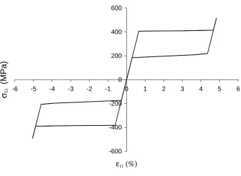
For the material properties listed in Table 1 which were determined from the experimental results of
McKelvey and Ritchie [8] based on the above described approach, the calculated stress-strain curve under
uniaxial loading condition is shown in Fig. 3. In this case, the applied stress is lower than the plastic yield
strength. No plastic deformation occurs and reverse transformation can occur completely after unloading.
Under uniaxial compression with the amplitude σ11, the transformation conditions are
11 ) 1 ( )
( =σtr = −α σ eq
for f
Y , for forward transformation (28a)
11 ) 1 ( )
( =σtreq = −α σ
res f
Y , for reverse transformation. (28b)
It is clear that for the same martensite volume fraction, the stress amplitude to trigger transformation under
compression is different from that under tension. The stress-strain curve in Fig. 3 shows asymmetry about
the origin point. Due to volume contraction during forward transformation for shape memory alloys, the
parameter α turns out to be negative. Therefore, the amplitude of the transformation stress under
compression is lower than that under tension in uniaxial loading condition for the same martensite volume
fraction, as shown in Figure 3.
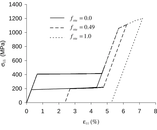
3.3 Plastic constraint
McKelvey and Ritchie [8] measured the variation of the recovery strain with the applied total strain in their
uniaxial tensile tests. The results suggested that the recovery strain decreased sharply after plastic
deformation. The minimum plastic strain to totally stabilize martensite (εcpl) is about 0.84%. Martensite will not transform back to austenite once material experiences plastic strain over this value. The linear function
of Eq. (14) can be applied to approximate the relation between the stabilized martensite volume fraction
sta
f and the experienced plastic deformation εpl. Figure 4 shows the influence of plasticity on reverse
transformation deformation at different loading levels under uniaxial tensile condition. These curves are
predicted using the combined constitutive model. In the first case, the applied maximum stress in less than
15 austenite as the force unloads to zero, i.e. fsta =0.0. In the second case as marked by the dashed curve, the plastic strain of 0.41% causes a volume fraction 49.0% of the martensite phase is stabilized. The total
residual strain is 2.4% at zero stress, much greater than the applied plastic strain. When the applied plastic
strain exceeds the critical value of 0.84%, reverse transformation is completely constrained, as indicated by
the dotted curve in Fig.4.
3.4 Effect of elastic mismatch
In the present model, the austenite phase and the martensite phase are assumed to have identical elastic
properties. In principle, however, there is no difficulty in allowing the elastic mismatch of the two phases
during transformation process. A simple way is to apply the linear mixture rule to evaluate the Young’s
modulus E of the bi-phase material,
m a fE
E f
E =(1− ) + , (29)
where Ea and Em are respectively the Young’s moduli of the austenite and the martensite, and f is the volume fraction of the martensite. The Poisson’s ratios can be still considered as the same or be treated using
a similar linear mixture rule. The elastic mismatch will not affect transformation model and the plastic
constraint equation in Section 2. However, in doing so, the calibration of material parameters will be
complicated.
Suppose that the elastic Young’s moduli of the austenite and the martensite are different, the averaged
Young’s modulus based on Eq. (29) is a function of the martensite volume fraction f, which changes with the
stress state. During uniaxial tensile loading process, the total strain rate can now be expressed as follows:
f fE
E
f a m
tr el
) 1 ( )
1 (
11 11
11
11 +β +α
+ −
σ =
ε + ε =
ε . (30)
The elastic strain rate will no longer linearly depend on the stress rate during transformation process.
volume fraction of the martensite could be determined during the transformation process. Practically, it is a
challenging task to measure the volume fraction of the martensite.
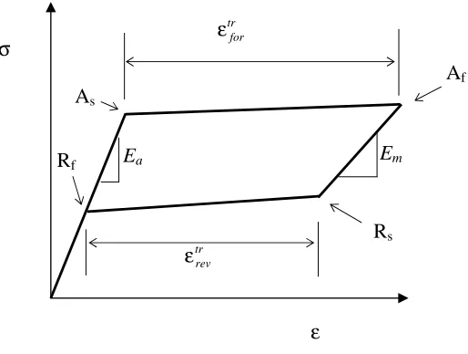
Figure 5 schematically illustrates a typical superelastic curve for NiTi, which manifests the difference of
elastic Young’s moduli. Similar experimental curves can be found in the literature [8, 24]. Here, As and Af
represent respectively the starting point and the finishing point of the forward transformation; and Rs the
reverse transformation starting point, Rf the reverse finishing transformation point. Due to superelastic
deformation, a closed hysteretic loop exists, which can be described by
tr rev el rev el m tr
for el
for el
a +ε +ε =ε +ε +ε
ε , (31)
where εela is the elastic strain created from Rf to As, εelfor the elastic strain during forward transformation
from As to Af, εtrfor the forward transformation strain, el m
ε the elastic strain amplitude from Af to Rs, εelrev the
elastic strain amplitude during reverse transformation from Rs to Rf and εtrrev the reverse transformation strain
amplitude. Generally, εelfor is close to εelrev because the transformation hardening effect is typically small. Therefore, the following approximation relation can be obtained,
tr rev el m tr
for el
a +ε =ε +ε
ε . (32)
For NiTi shape memory alloys, the Young’s modulus of the martensite is one-third to one half of that of the
austenite for NiTi. Therefore, εelm can be much larger than εela, which is can be shown in Fig. 5. In other words, we have such conclusion,
tr rev tr
for >ε
ε . (33)
It means that the elastic strain has “consumed” part of the forward transformation strain during unloading
process before reverse transformation starts at point Rs, and the total forward transformation strain is “not
equal” to the total reverse transformation strain even so the reverse transformation is obviously finished
17 In reality, the reverse transformation might have already started before reaching the corner point Rs.In this
case, it is practically difficult to determine precisely the onset of reverse transformation. It might also be
possible that the macroscopic transformation strain rate is not proportional to the transformation volume
fraction rate due to twinning phenomenon between different martensite variants. Further experiments should
be designed to explain the “non-equilibrium” between the forward transformation strain and reverse
transformation strain, and so as to establishing appreciated mathematical models to quantify this
phenomenon. It is worthy to reiterate that the model in Section 2 can successfully describe superelastic
deformation within acceptable accuracy although it neglects the elastic mismatch.
3.5 Effect of hydrostatic stress
The equivalent transformation stress σtreq =σeq +3ασm in (5) is the transformation driving force, where
m
ασ
3 represents the contribution from the hydrostatic stress. Similar relation has been used by Spitzig and
Richmond [25] to study the effect of pressure on the flow stress of iron-based bcc materials, where pressure
influences the dislocation motion. Here, the effect of the hydrostatic stress creates due to the transformation-
induced volume change, which is represented by the parameter α. The value of the parameter α is negative
for shape memory alloys. It is expected pure hydrostatic pressure will contribute to the transformation
driving force. In other words, if a uniaxial test were carried out with a hydrostatic compression, the critical
tensile stress to trigger transformation would decrease with increasing hydrostatic pressure. To our
knowledge, so far no such experiment has been reported. But, the effect of hydrostatic pressure was
examined in an alternative way by Kakeshita et al [26]. They experimentally studied the influence of the
hydrostatic pressure on the transformation temperature. For thermoelastic martensitic transformation
occurring in shape memory alloys, not only mechanical loading but also thermal loading by reducing
temperature can drive transformation. Because the hydrostatic pressure can increase the forward
transformation driving force, it is expected that under higher hydrostatic pressure less transformation thermal
the transformation temperature increased linearly with increasing pressure for some NiTi shape memory
alloys.
On the other hand, hydrostatic tensile stress should resist transformation. In fracture mechanics, triaxial
hydrostatic constraint is normally quantified in terms of the ratio of the hydrostatic stress to the von Mises
equivalent stress, σm/σeq. Focusing on forward transformation, the onset of phase transformation can be rewritten as
eq for eq m Y
σ = σ σ α
+3 (0.0)
1 , (34)
which means that the higher the triaxility ratio σm/σeq, the more difficult it is to trigger forward transformation. The influence of triaxiality also strongly depends on the value of the material parameter α.
Because the transformation volume strain is much smaller than stress-induced transformation shear strain in
shape memory alloys, according to Eqs. (16) and (17),, the amplitude of α is much smaller than 1.0, which
is –3.15% in the above considered case. Thus, the influence of the triaxiality on transformation should be
rather limited.
McKelvey and Ritchie [8] found that forward transformation did not occur ahead of the crack tip in their
experiment. They hypothesized that the high hydrostatic tensile stress at the crack tip suppressed the
transformation due to negative transformation volume strain. Since the triaxiality σm/σeq ahead of a three-dimensional crack is about 3.0 [27], and that the term Yfor(0.0)/σeq is approximately zero at the crack tip due to the singular behaviour of σeq at the crack tip, the value of α should be around –11.0% in order to completely suppress phase transformation at the crack tip. This corresponds about –1.5% transformation
volume contracting. This amplitude is much larger than the measured value of -0.39% in NiTi shape
memory alloy. In a separate test, based on the measured macroscopic stress-strain curves, McKelvey and
19 1
. 1 /σ =
σm eq . Clearly further experimental studies are needed to investigate the sensitivity of the
hydrostatic tensile stress on forward phase transformation.
4. Phase Transformation and Plastic Deformation at the Tip of a Tensile Crack
The constitutive model outlined in Section 2 has been implemented as a user material subroutine for the
finite element code ABAQUS [17] to analyse the phase transformation and plastic deformation of a
superelastic structure under complex loading condition. Here as an example of application, the
transformation and plastic deformation field near the tip of a tensile crack in a NiTi superelastic shape
memory alloy is analyzed. In this case, a semi-infinite plane-strain crack subjected to remote K field is I considered. Due to symmetry, only a half of the whole model is simulated. Figure 6(a) shows the entire mesh
and the boundary condition. For a given value of K , the corresponding displacement field is imposed on I the boundary far away from the crack tip. Here the value of K is chosen as 60 I MPa m. A very fine mesh is employed near the crack tip, which is illustrated in Fig. 6(b). The material constants calibrated in Section 3
are used in the calculation.
Figure 7(a) shows the distribution of the martensite volume fraction, f, near the crack tip under the given
value of K . It shows that there exists a full transformed zone very close to the crack tip with f reaching to I the maximum value 1.0. Outside that region, the martensite volume fraction reduces gradually with the
distance away from the crack tip. As indicated in this figure, the normalized height of the transformation
zone, 2
)] 0 ( / [ I pl
tr
Y K
y
, at the contour line f =0.25 is 0.90. The total normalized height of the transformation
zone is 2.1. Figure 7(b) shows the distribution of the triaxial hydrostatic constraint, σm/σeq, near the crack tip. It indicates the highest value of σm/σeq is about 4.15, comparing with a value of 3.0 for a crack in a non-transformation material, which appears just in front of the crack tip. Comparing Figures 7(a) and 7(b),
than 0.76 while transformation having completed with f =1.0. Even if the critical hydrostatic constraint to suppress transformation is as low as 1.1 as determined by the notched tensile bar test from [8], it seems that
transformation could still occur in the region with lower σm/σeq near the crack tip, which might affect the failure behavior of the superelastic material as the influence of transformation on the toughness in ZrO2
ceramics [28, 29].
Figure 8(a) shows the plastic deformation field near the crack tip. As Figures 7 and 8 are in the same scale, it
clearly indicates that the plastic zone is much smaller than the transformation zone near the crack tip. The
normalized plastic zone height, 2 )] 0 ( / [ I pl
pl
Y K
y
, is 0.12. Comparatively, the estimated value from linear
elastic fracture mechanics is about 0.13 [30]. In this case, the phase transformation has little effect on the
size of the plastic zone because the plastic yield strength is much larger than the transformation stress. The
distribution of the stabilized martensite volume fraction due to plastic transformation is shown in Fig. 8(b).
Stabilized martensite near the crack tip may have significant influence on the fatigue crack growth in this
kind of materials. Applying fracture mechanics, the influence of transformation, plastic deformation and
plastic stabilized martensite on fracture and fatigue behavior is being carried out.
5. Conclusions
The influence of plastic deformation on reverse transformation in superelastic shape memory alloys has been
quantified by a constitutive model that accounts for both phase transformation and plasticity. A macroscopic
phenomenonological model based on generalized plastic theory is adopted to describe the superelastic
deformation behaviour. The forward and reverse transformation process is described by the change of the
martensite volume fraction, which is determined by the consistency transformation condition. This
transformation model involves the change of material volume due to transformation. It can account for the
influence of hydrostatic stress on transformation conditions. The effect of the plasticity on the transformation
reverse transformation. The present constitutive model has been applied to investigate the crack-tip
deformation behaviour of a tensile crack in a superelastic shape memory alloy.
Acknowledgements
This work was financially supported by the ARC Large Research Grant (A10009166). Y-W Mai wishes to
thank the Australian Research Council for the award of a Federation Fellowship tenable at the University of
Sydney.
References
[1] H. Funakubo, Shape Memory Alloys. Gordon and Bleach, New York, 1987, p. 270.
[2] V. Birman, Appl. Mech. Rev. 50 (1997) 629.
[3] J. Van Humbeeck, Mater. Sci. Eng. A273-275 (1999) 134.
[4] T. W. Duerig, A. R. Pelton, D. Stoeckel, Mater. Sci. Eng. A273-275 (1999) 149.
[5] T. W. Duerig, A. R. Pelton, D. Stoeckel, Bio-Medical Mater.Eng. 6 (1996) 255.
[6] D. Y. Li, Smart Mater. Struct. 9 (2000) 717.
[7] A. L. McKelvey, R. O. Ritchie, J. Biomedical Mater. Res. 47 (1999) 301.
[8] A. L. McKelvey, R. O. Ritchie, Metall. and Mater. Trans. A32 (2001) 731.
[9] F. D. Fischer, Q.-P. Sun, K. Tanaka, Appl. Mech. Rev. 49 (1996) 317.
[10] C. Liang, C. A. Rogers, J. Intelligent Mat. Syst. Struct. 1 (1990) 207.
[11] Q.-P. Sun, K.-C. Hwang, J. Mech. Phys. Solids, 41 (1993) 1.
[12] E. Patoor, A. Eberhardt, M. Berveiller. Arch. Mech. 40 (1988) 775.
[13] W. Yan, Q.-P. Sun, K.-C. Hwang, Science in China (Series A) 28 (1998) 275.
[14] F. Auricchio, R. L. Taylor, J. Lubliner, Comput. Methods Appl. Mech. Engrg 146 (1997) 281.
[15] J. Lubliner, F. Auricchio, Int. J. Solids Struct. 33 (1996) 991.
[16] N. Rebelo, N. Walker, H. Foadian, in 2001 ABAQUS User’s Conference 2001.
[18] D. E. Hodgson, M. H. Wu, R. J. Biermann, Shape memory alloys, in: Metals Handbook. 10th editon, v.
2. American Society for Metals. Cleverland, Ohio. 1991. pp.897-902.
[19] J. Lemaitre, J.-L. Chaboche, Mechanics of Solid Materials. Cambridge University Press. 1990, p. 556.
[20] C. H. Wang, W. Hu, J. Sawyer, Computational Mechanics 26 (2000) 140.
[21] W. Yan, E. P. Busso, N. P. O’Dowd, Proceedings of Royal Society London, Series A456 (2000) 1.
[22] D.-N. Fang, W. Lu, W. Yan, T. Inoue, K.-C. Hwang, Acta mater. 47 (1999) 269.
[23] R. L. Holtz, K. Sadananda, M. A. Imam, Int. J. of Fatigue 21 (1999) s137.
[24] P. H. Lin, H. Tobushi, K. Tanaka, T. Hattori, M. Makita, J. Intell. Mater. Syst. Struct. 5 (1994) 694.
[25] W. A. Spitiz, O. Richmond, Acta Metall. 32 (1984) 457.
[26] T. Kakeshita, K. Shimizu, S. Nakamichi, R. Tanaka, S. Endo, F. Ono, Materials Transactions, JIM 33
(1992) 1.
[27] W.Yan, G. Shan, O. Kolednik, F. D. Fischer, Key Engineering Materials 145-149 (1998) 179.
[28] R. M. McMeeking, A. G. Evans, J. Am. Ceram. Soc. 65 (1992) 242.
[29] B. Budiansky, J. W. Hutchinson, J. C. Lambropoulos, Int. J. Solids Struct. 19 (1983) 337.
[30] T. L. Anderson, Fracture Mechanics: Fundamentals and Applications. Second Edition, CRC Press, Boca
Article submitted to Materials Science and Engineering: A 23 Table 1. Part material data of a NiTi superelastic SMA calibrated from [8].
E Yfor(0) Yfor(0.6) Yfor(1) Yres(1) Yres(0.85) Yres(0) Ypl(0) Ypl(0.32%) Ypl(0.84%) Ypl(1.68%) Ypl(2.70%)
Figure 1. Illustrating superelastic deformation mechanism. Loading
Unloading
11
ε
11
σ
[image:25.612.152.379.131.346.2]E
Figure 2. Illustration of the calibration process for the forward transformation hardening function from a uniaxial tensile stress-strain curve.
f = 0
11
σ ∆
11
ε ∆
tr
11
ε
∆ el
11
ε ∆
for
C 0
σ
Figure 3. Predicted superelasticity under uniaxial loading condition. -600
-400 -200 0 200 400 600
-6 -5 -4 -3 -2 -1 0 1 2 3 4 5 6
ε11 (%)
σ
11(
M
P
a
Figure 4. Stabilized martensite volume fractions due to different plastic deformation amplitude and their influences on stress-strain curves under uniaxial tension condition.
0 200 400 600 800 1000 1200 1400
0 1 2 3 4 5 6 7 8
ε11 (%)
σ11
(
M
P
a
)
fsta=0.0
fsta=0.49
fsta=1.01.0 49 . 0
0 . 0
= = =
sta sta sta
ε σ
Em Ea
tr for
ε
tr rev
[image:28.612.153.410.157.351.2]ε
Figure 5. Schematic illustrating the “non-equilibrium” between the forward and reverse transformation strains in a typical uniaxial tensile test.
As
Af
Rs
VALUE
0.0 +2.50E-01 +5.00E-01 +7.50E-01 +1.00E+00
/ VALUE
-9.32E-01 -8.53E-02 +7.61E-01 +1.61E+00 +2.45E+00 +3.30E+00 +4.15E+00
VALUE
0.0 +1.26E-01 +2.53E-01 +3.79E-01 +5.05E-01 +6.32E-01
VALUE
![Table 1. Part material data of a NiTi superelastic SMA calibrated from [8].](https://thumb-us.123doks.com/thumbv2/123dok_us/355117.66909/23.612.51.719.168.229/table-material-data-niti-superelastic-sma-calibrated.webp)