Theses
8-13-2019
A Performance Analysis of the Meshed Tree
Protocol and the Rapid Spanning Tree Protocol
Peter Willis
Follow this and additional works at:https://scholarworks.rit.edu/theses
This Thesis is brought to you for free and open access by RIT Scholar Works. It has been accepted for inclusion in Theses by an authorized administrator of RIT Scholar Works. For more information, please [email protected].
Recommended Citation
A Performance Analysis of the Meshed Tree Protocol and the Rapid
Spanning Tree Protocol
by
Peter Willis
Committee Members
Prof. Nirmala Shenoy
Prof. Hrishikesh Bhatt Acharya
Prof. John Hamilton
Thesis submitted in partial fulfillment of the requirements for the degree of
Master of Science in
Networking and Systems Administration
Rochester Institute of Technology
B. Thomas Golisano College
of
Computing and Information Sciences
08/13/2019
B. Thomas Golisano College
of
Computing and Information Sciences
Master of Science in Networking and Systems
Administration
Thesis Approval Form
Student Name: Peter Willis
Thesis Title:
A Performance Analysis of the Meshed Tree
Protocol and the Rapid Spanning Tree Protocol
Thesis Committee
Name
Signature
Date
Nirmala Shenoy
Chair
Hrishikesh Bhatt Acharya
Committee Member
John Hamilton
_____
Committee Member
This work would not have been possible without the support and wisdom of many people in my life. To my committee members, Dr. Nirmala Shenoy, Dr. H.B. Acharya and Dr. John Hamilton for their support of my scholarly pursuits now and in the future. To Bruce Hartpence and Johnathan Weissman for constantly teaching me what it means to be passionate about computer networking. And finally, to my friends, family, and wife, Cassandra, who also has the pleasure of dealing with all of my scholarly pursuits.
my future as a doctoral student
1 Abstract 1
2 Introduction 2
2.1 Motivation to Study . . . 2
2.2 Goals and Objectives . . . 4
3 Background 7 3.1 Meshed Tree Protocol and Algorithm . . . 7
3.1.1 MTP Protocol Data Unit . . . 8
3.1.2 Convergence of an MTP-based Switched Network . . . 15
3.2 Rapid Spanning Tree Protocol and Algorithm . . . 21
3.2.1 RSTP Protocol Data Unit . . . 22
3.2.2 Convergence of an RSTP-based Switched Network . . . 28
4 Prior Work 34
4.1 RSTP Performance Analysis . . . 34
4.2 MTP Performance Analysis . . . 37
5 Methodology 40 5.1 Materials . . . 40
5.2 Measurements . . . 43
5.3 Procedures . . . 45
6 Results 54 6.1 5 Node Topology Results . . . 54
6.1.1 5 Node Topology Data . . . 54
6.1.2 5 Node Topology Discussion . . . 55
6.2 10 Node Topology Results . . . 58
6.2.1 10 Node Topology Data . . . 58
6.2.2 10 Node Topology Discussion . . . 59
6.3 17 Node Topology Results . . . 62
6.3.1 17 Node Topology Data . . . 62
3.1 The MTP JOIN Message . . . 8
3.2 The MTP ADVT Message . . . 10
3.3 The MTP Host ADVT Message . . . 12
3.4 Initial VID Propagation in MTP . . . 15
3.5 Continued VID Propagation in MTP . . . 17
3.6 Formalizing the Broadcast Tree in MTP . . . 17
3.7 Host Table Construction in MTP . . . 19
3.8 Failure Recovery in MTP . . . 20
3.9 RSTP BPDU . . . 23
3.10 An RSTP topology when initialized . . . 28
3.11 RSTP tiebreaker process . . . 30
3.12 RSTP blocking process . . . 32
5.1 Traffic Generation Example . . . 46
5.2 5 Node Topology . . . 49
5.3 10 Node Topology . . . 50
5.4 17 Node Topology . . . 51
5.5 The Automation Framework . . . 52
3.1 802.1w RSTP Port Roles . . . 32
3.2 802.1w RSTP Port States. . . 33
6.1 5 Node Results - Topology Reconvergence Averages (sec.) 54
6.2 5 Node Results - Client Broadcast Frame Loss . . . 55
6.3 5 Node Results - Client Unicast Frame Loss . . . 55
6.4 10 Node Results - Topology Reconvergence Averages (Sec.) 58
6.5 10 Node Results - Client Broadcast Frame Loss . . . 59
6.6 10 Node Results - Client Unicast Frame Loss . . . 59
6.7 17 Node Results - Topology Reconvergence Averages (Sec.) 62
6.8 17 Node Results - Client Broadcast Frame Loss . . . 63
6.9 17 Node Results - Client Unicast Frame Loss . . . 63
Abstract
Loop avoidance is essential in switched networks to avoid broadcast storms. Logical Spanning Trees are constructed on the physical meshed topologies to overcome this issue and preserve the stability of the network. However, during topology changes as the result of a failure, frame forwarding latency or frame loss is introduced when re-converging and identifying new spanning tree paths. The Meshed Tree algorithm (MTA) offers a new approach. Meshed Trees support multiple tree branches from a single root to cut down on re-convergence latency on link failures. A Meshed Tree Protocol (MTP) based on MTA is currently under development as an IEEE standard. MTP is evaluated for convergence delay and frame loss in comparison with Rapid Spanning Tree Protocol (RSTP) on the GENI testbed.
Introduction
2.1
Motivation to Study
The world today is one that is hyper-connected, and the applications which run over the Internet (and computer networks in general) are expected to provide service at high speeds. As a core networking layer, the data-link layer is fundamental to all networks and applications that rely on networking. While loop-avoidance protocols are necessary for switched networks to continue to support physical redundancy, the study of these protocols and further developments in this space is limited. There have been efforts from both the Internet Engineering Task Force (IETF) and the Institute of Electrical and Electronics Engineers (IEEE) to standardize new loop-avoidance protocols, but their efforts have resulted in complex solutions. Arguably the biggest issue with these protocols, as well as the motivation behind the Meshed
Tree Protocol (MTP), is that the current protocols are complex and may not con-verge at a rate deemed acceptable by organizations running the network. By taking a working implementation of MTP and running tests that can be replicated by the same topology running the Rapid Spanning Tree Protocol (RSTP), conclusions can be drawn on MTP and if the protocol as designed allows for faster convergence.
While hardware researchers continuously innovate as well as advance on a number of fronts to provide end-users a better experience, protocols implemented in software which help keep networks up and running are not keeping up with these changes. This causes networking hardware that can maximize throughput to be held back while the underlying control protocols make decisions about how traffic should be forwarded. This issue becomes apparent when looking at RSTP, as a failure on a switch that is participating in the network’s spanning tree can cause the entire tree to be rebuilt through topology change messages that need to span the entire network [1]. During this reconvergence period, frames originating from end-nodes (employees and customers devices) are blocked or lost, thus creating a period of time where no traffic flows through the switched network. While RSTP improved upon the original Spanning Tree Protocol by speeding up recovery efforts, the resulting convergence delays are still unacceptable to today’s communication speeds.
protocol have all been scrapped in favor of starting fresh with protocols that bring IS-IS-based routing into the data-link layer, even though RSTP is still the standard run in client-based switched networks. MTP, on the other hand, is still very much an in-progress standard based on a novel algorithm that has the ability to grow and change based on the results of this study. Getting a baseline for how the test implementation of MTP functions now will allow future researchers who are working on this project to get a sense of where there is room for improvement. Protocol design is a tough, iterative endeavor, and any way of making future iterations easier to visualize as well as plan out will have a lasting impact on the success of the protocol in getting standardized and onto production networks.
2.2
Goals and Objectives
MSTP [4]. This will make future MTP testing easier and will help set up processes as well as procedures that can be followed without having to start from scratch when bringing on new individuals to the project.
Background
3.1
Meshed Tree Protocol and Algorithm
MTP uses a collection of different fields that make up different messages for its PDU, known as a Meshed Tree PDU (MTPDU). The overhead is very low, resulting in an easy troubleshooting process. In the case of the JOIN message and the HELLO message, the overhead is reduced down to a single byte that is shared by all of the MTP messages: the Message Type. As the field name suggests, the Message Type field is used to differentiate between MTP messages so that an MTP implementa-tion can properly parse its informaimplementa-tion. Each MTP message type is given a single identifier, and due to the length of the field being a full byte, additional MTP mes-sage types could be defined to future-proof the protocol. Per the MTP standard [6], the message type is always the first field that is included in an MTPDU. MTPDU‘s
are exchanged as a means to build or modify a number of tables that exist on each Meshed Tree Switch (MTS). Tables are split up by traffic type, unicast or broad-cast. Broadcast traffic is handled through the use of MTP Virtual Identifiers (VIDs), which are received and attached to an interface on a MTS and ranked to determine efficient paths to the root. The best VIDs are placed in a Main VID table, while the rest are placed in a backup table. The number in each table is configurable based on network needs. VIDs also create parent-child pairings, where children of an MTS is stored in a child VID table. Unicast traffic is given its own Host Address Table (HAT), where client MAC addresses and the interface on which to send on is noted. These tables are used to build the Meshed Tree so that forwarding decisions can be made for the network. A breakdown of each MTPDU message is seen in section 3.1.1 and an explanation of MTP‘s convergence process is in section 3.1.2.
3.1.1
MTP Protocol Data Unit
MTP JOIN
Through the use of a JOIN message, a switch running an MTP implementation can signal its desire to join the switched networks meshed tree. By broadcasting on its active interfaces with the JOIN message, neighboring MTS‘ who have already joined the Meshed Tree respond with the appropriate information so that the source switch can participate. Broadcasting is done in the case of this MTPDU because the status of neighboring nodes can not be properly determined until some sort of response (or lack thereof) is received. At the start of a Meshed Tree topology, only the root MTS will have the information and capabilities necessary to build the Meshed Tree. Thus, its nearest neighbors who wish to be a part of the meshed tree will receive the first wave of responses to their JOIN messages. Switches who sub-sequently join the switched topology then receive additional information from those first-hop nodes from the root, and so on until the tree has been stabilized. In the event that a JOIN message is received by a node that has yet to hear anything back from its own attempts at joining the Meshed Tree, the JOIN message will be silently ignored. Those nodes that do not hear back from the JOIN message broadcasts will make another attempt at joining the Meshed Tree after a predetermined amount of time has passed, which is based on a configurable value set by an administrator of the network.
MTP VID ADVERTISEMENT
Figure 3.2: The MTP ADVT Message
message sent by another node wishing to become a part of the Meshed Tree, an ADVERTISEMENT message is used to disseminate VIDs that make up different branches of the tree. By giving other nodes their VID information, they can then properly modify their VID tables for broadcast traffic. ADVERTISEMENT mes-sages can also be used to prune the Meshed Tree when necessary. Pruning is needed when a node has determined there has been a failure on an interface that is config-ured with a VID (either by a local failure of the interface or a timeout), or when a VID that was previously considered a main VID is then replaced with better options that need to be notified to other MTS. Adaptability to a networks or organizations needs is also built into this type of message, as there are a number of configurable options that are then reflected in its fields.
Message Type:
The message type is used to differentiate between the different types of MTPDUs. In the case of the ADVERTISEMENT message, the value is set to 3.
Operation:
MTS whether or not the VIDs included in the message should be candidates for addition or to be used as the basis for VID pruning. In the event of an addition operation (a value of 1), each VID currently held is checked against the cost of the candidate VID(s) and if it makes sense to add it to a table based on its path cost as well as the size of the tables. For a deletion operation (a value of 2), every current VID is checked to see if the VID(s) included in the message is its prefix. If a prefix match is found, then that VID is then removed from its respective table.
Number of VIDs:
This field is used to tell the receiving MTS the number of VIDs included in the message. This is needed for parsing purposes, as each VID included has a set number of fields and the MTP implementation can determine how long the message is. The Message Type, Operation, and Number of VIDs fields are in the fixed fields of the message and are included with every ADVERTISEMENT message. The remaining fields are only added for each VID that is included. The maximum number of VIDs included in one ADVERTISEMENT message is directly correlated to the max number of main VIDs.
Path Cost:
VID Address Length:
In a similar fashion to the Number of VIDs field, this field is used for parsing purposes to give the receiving MTS an idea of how long the VID is and how to read the entire identifier properly. This is needed due to the variable-length nature of a VID, which will grow as the number of hops away from the root node grows.
Meshed Tree Protocol Virtual Identifier (VID):
The VID itself, which is the value used to define the path from the root MTS to the MTS receiving the VID. VIDs, in their current iteration, are formatted us-ing a dotted decimal notation. The rankus-ing/orderus-ing of VIDs will determine how broadcast traffic will be propagated from a node, and the meshed nature of switched networks will create a number of different VID options for nodes to store and pick from as backups.
[image:23.612.124.529.499.612.2]MTP HOST ADVERTISEMENT
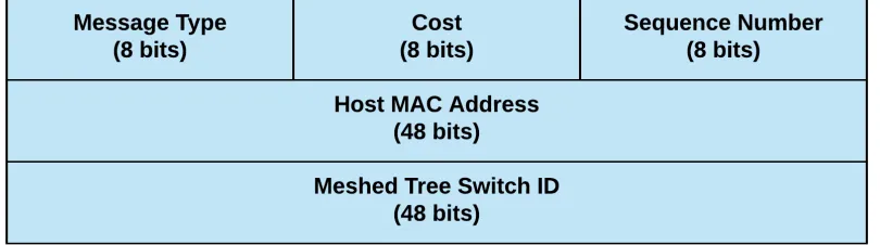
The forwarding decisions made for broadcast traffic and unicast traffic are mu-tually exclusive in MTP, which created the need for an advertisement message that manages the tables corresponding to each type of traffic. Broadcast traffic is handled via the creation of Meshed Trees, which are built using the VID ADVERTISEMENT seen in Fig. 3.1.1. For unicast traffic, host tables are populated for each node partici-pating in MTP with a HOST ADVERTISEMENT message so traffic is forwarded on the most cost effective path. Because broadcast traffic is forwarded via the Meshed Tree, which does not shut down any interfaces, all links in the switched network can be used. A system of sequence numbers is used for updated information when a client node is moved or a link becomes unavailable, and the cost metric previously described in the VID ADVERTISEMENT is also used for ranking potential host entry additions.
Message Type:
In the case of the HOST ADVERTISEMENT message, the value is set to 4.
Cost:
The value placed on all links between the MTS directly connected to a specific host and the MTS receiving the message. Just as with the VID ADVERTISE-MENT, cost is a dynamic value that can change based on how it is configured by an administrator.
Sequence Number:
unicast traffic should be forwarded on the switched network. When an MTS receives a host advertisement with a sequence number that is greater than what is currently stored for that particular host, the information that is present in the message over-writes what is currently entered for the host.
Host MAC Address:
The IEEE 802.3 48-bit, hexadecimal, globally unique identifier of a client inter-face attached to the switched network running MTP. The host MAC Address is used to identify each client on the network and what interface traffic should be forwarded out of to get closer to the device.
Meshed Tree Switch ID:
The MAC Address with the lowest value on an MTS. It is used to identify which MTS is directly connected to the node. Because a client could be unplugged and plugged into a different MTS on the switched network, this value will update and replace old entries that include a different Switch ID.
MTP HELLO
to an end-node not running MTP), HELLO messages are expected to be sent and received at regular intervals as configured. For each HELLO message received, entries in the various tables used by MTP are checked for the MAC address of the adjacent node. If an entry, VID or host, is found, a timer attached to that entry is updated with the current time. In the event that the configured time to hear from a node is exceeded, it is assumed that all entries that were received from that interface are now invalid and need to be deleted. Like many other control protocols (including RSTP), a heartbeat function is used to check on the health of a connection to an adjacent node that may have a software/protocol failure that could not be communicated otherwise.
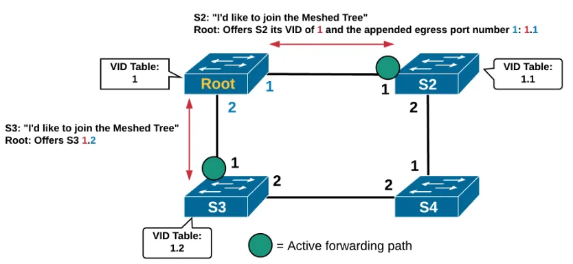
[image:26.612.121.538.430.622.2]3.1.2
Convergence of an MTP-based Switched Network
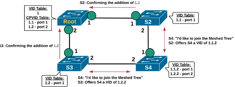
Figure 3.5: Continued VID Propagation in MTP
Figure 3.6: Formalizing the Broadcast Tree in MTP
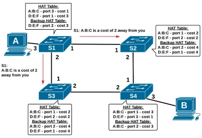
[image:28.612.119.528.287.525.2]Figure 3.7: Host Table Construction in MTP
HAADVT which contains client As information is flooded on all MTP ports, and each switch will eventually receive the advertisement on each of its own MTP ports. Each hop away from the client requires that the cost be increased by a value of one. The lowest-cost port for each node is added to the Host Address Table (HAT) as a primary entry, and the second lowest-cost port for each node is added as a backup HAT entry. When client data comes in an interface on a switch, the destination MAC address is checked against the primary HAT entry, and forwarded out of the interface associated with the entry. This happens at each hop until the destination client receives the data.
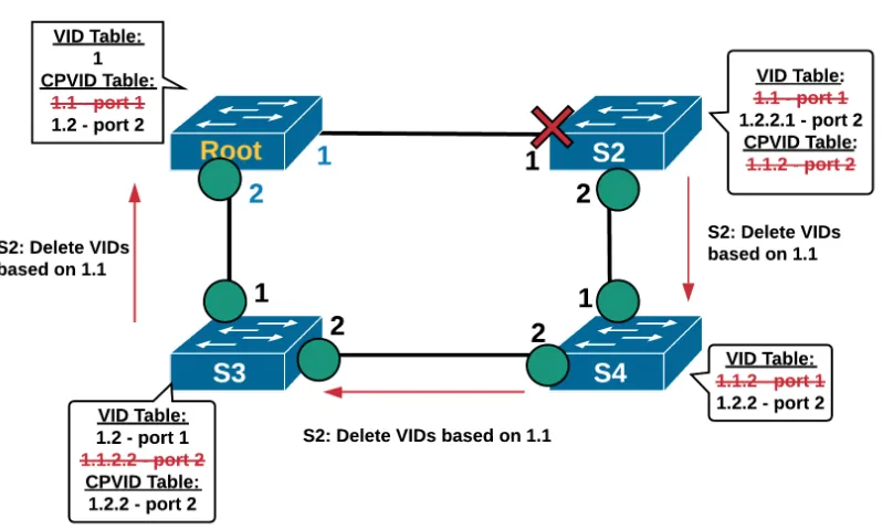
Figure 3.8: Failure Recovery in MTP
both its broadcast tree and its unicast paths. For VIDs associated with a break, a VID advertisement message is sent with the deletion operation set, and the affected VIDs are deleted. For each neighbor that has a prefix of that broken VID, that message is taken exactly as its received, and again forwarded to all of its neighbors. This process continues until every VID associated with the failure has been pruned. In Fig. 3.8, the break on port 1 on S2 means that VID 1.1 has failed. This means that S2 needs to remove its PVID and its CPVID, S4 needs to remove its PVID, S3 needs to remove its secondary VID, and root S1 needs to remove one of its CPVIDs. In this process, the flow of the tree has shifted, as S4 now has a PVID based on S3s 1.2, which means that S4 is now the child of S3. S3 notes this when it receives the updated VID information after the pruning has been completed. A similar situation happens for the HAT tables, as sequence numbers are incremented and the new costs to reach end nodes causes the tables to switch to backup entries.
3.2
Rapid Spanning Tree Protocol and Algorithm
distributed approach in which each switch exchanges bridge protocol data units (BPDUs) to maintain active forwarding paths throughout the switched network that come together to form a spanning tree. Spanning trees originate from the field of graph theory, and are a type of graph in which vertices (the switches) are connected via a minimal number of edges (links/segments), thus creating a graph that does not contain loops between the vertices. Graph theoretic algorithms are used in communication protocols, particularly those that deal with routing and switching, as a computer network can be abstracted as a graph. Perlman [8], who authored the original STP standard, starts her seminal paper off with a poem titled Algorhyme in which she explains that a tree graph is perfect for her protocol because it spans the entire switched network while also maintaining loop-free paths.
3.2.1
RSTP Protocol Data Unit
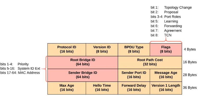
Figure 3.9: RSTP BPDU
layer, thus there is no logical addressing and the BPDU is encapsulated directly by Ethernet headers. MTP is encapsulated and transported over an Ethernet II frame header, but a BPDU runs over both an 802.3 Ethernet header and a 802.2 Logical-Link Control (LLC) header which contains a DSAP and SSAP of 0x42 corresponding to STP variants. The destination MAC address of a BPDU is 01:80:C2:00:00:00, a layer 2 multicast address that will only be picked up and read by switches that are running STP variants, including RSTP.
Protocol Identifier:
Protocol Version Identifier:
Beyond the basic protocol identifier, the version identifier helps the receiving switch understand which version of STP is in use, and as a result which version of the BPDU is in use. This is important in the context of the flags, as a standard STP BPDU would skip over a number of flags that are otherwise in use in RSTP.
BPDU Type:
This type field is not important in the context of RSTP, as there is only one type of RSTP BPDU. In the original STP, there were a number of BPDUs that could be received that corresponded to different tasks, such as the notification of a topology change or a standard configuration BPDU to keep neighboring switches up to date with its latest information. At its core, like the previous two fields, this field is meant to tell the receiving switch how to properly parse the PDU.
BPDU Flags:
Change (there has been a topology change).
Root Bridge Identifier and Sender Bridge Identifier:
As a means to identify as well as classify switches which participate in RSTP, each switch uses a bridge identifier (BID) to communicate with neighboring switches running RSTP. A bridge identifier is split into three sections: the priority, system ID extension, and MAC address. The priority is the first four bits in the field and is an integer describing the value placed on the bridge that is a multiple of 4096. By default, the priority of a bridge is 32,768. The system ID extension is the next 12 bits and is used when VLANs are introduced in the topology, as the VLAN ID is used as the extension and added to the priority. When comparing two switches, the one with the lower priority would be considered a more important switch. When the priorities are the same, the MAC address, the final section of a BID, determines which switch wins the tie. Like the priority, a lower MAC address is considered better. For example, a bridge with a BID of 32,768-0-00:00:00:00:00:01 will be considered superior against a bridge with a BID of 32,768-0-00:00:00:00:00:02. A switch‘s BID, which could include a default priority or a custom one, is included in the Sender BID section. The Root BID informs neighboring switches which switch the node believes is the root of the tree. The root is determined by every switch in the topology agreeing on one Root BID, which will be the switch with the lowest personal BID. The sending BID is also used as a tiebreaker between nodes in the event that the Root Path Cost is equal between two or more interfaces.
This field describes the sum of all of the interface costs between a specific switch‘s interface and the root bridge. The greater the capacity/bandwidth associated with an interface, the lower the cost is for the interface by default. Interfaces can be customized with their own Root Path Cost (RPC) to perform a form of traffic engineering so that certain links between switches are favored over others. Once a root node is chosen for the topology, RPC values take over as the dominant metric in determining which role is given to which interface between two switches. In the event RPC values are the same between switches or between two interfaces on a switch, Sender BID is used as a tiebreaker.
Port Identifier:
The port identifier is the all-else-fails tiebreaker of RSTP in determining roles between switches. This identifier will never be used in a common switched network, as the need for it only arises when two switches are redundantly connected through two or more links that are not logically combined into one interface. This tiebreaker is necessary because multiple interfaces on the same switch will contain the same Root BID, RPC, and sender BID. In order to determine which interface needs to be disabled, the sender port identifier is used. Much like an RSTP BID, the port identifier is made up of multiple parts: a port priority and port number. The default priority is 128 (0x80) and is added to the front of the port number. For example, a switch with an active port 24 would have a port identifier of 0x8018, where 0x18 is the hexadecimal representation of 24.
Due to the expanded nature of RSTP over STP, this field has a new purpose beyond what it was originally intended for. It is now used as a hop count so that each hop beyond the root bridge increments the value by one when receiving a BPDU on its root port. If the message age is equal to the max age field, the BPDU is dropped because the max radius of the network has been eclipsed. Messages in the original STP were copied and flooded from the root, which required a time-to-live function, but now BPDU‘s are never forwarded past the link that they are sent on.
Max Age:
Used in tandem with the message age field to tell nodes the farthest number of hops that can be used from the root. If this field is set to 10 for example, that means a switch 11 hops from the root would not be able to participate in that RSTP topology. This field is customizable and is static once configured.
Hello Time:
The defined frequency, in seconds, that the receiving switch should hear from the sending switch. By default, this value is set to 2, which means that a switch should receive an RST BPDU every two seconds. If a message is not received in 3 x hello time, then the link is assumed dead and the reconvergence process begins.
Version 1 Length:
3.2.2
Convergence of an RSTP-based Switched Network
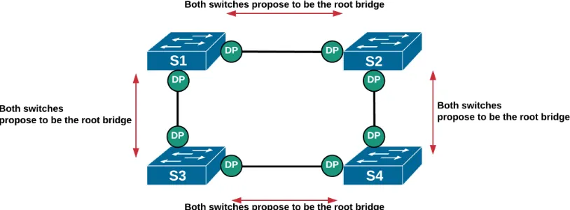
Figure 3.10: An RSTP topology when initialized
have P2P connections to other devices, they place their respective interfaces in a designated port role as well as a discarding port state. This also causes the switches to send out BPDUs from those interfaces with the proposal flag set, which tells the adjacent switch that it believes it has superior information. This information is the Root Bridge ID (RBID), root path cost (RPC), as well as its own Bridge ID (BID). A switch that has just been enabled will consider itself the root switch until a better RBID is received. This behavior can be seen in Fig. 3.10. Once the four switches in the topology exchange proposal BPDUs, they analyze the other switchs RBID, BID, and RPC and decide whether or not they agree with the proposal. In this example topology, Switch 1 (S1) has a lower RBID (itself) than the received BPDU from Switch (S2), making it an inferior proposal that is ignored. When S2 sees that the BPDU from S1 is superior, S2 changes the role of its interface connected to S1 from designated to root and begins a syncing process. To account for this change in the topology, S2 puts all other active interfaces that are not edge ports (interfaces that are connected to end-nodes) or interfaces in the discarding state into a designated and discarding state. Once all interfaces on S2 are synced, S2 takes the superior BPDU sent by S1 and changes the flag from proposal to agreement without making any other changes, including the sender BID field so S1 knows exactly what is being agreed to. This agreement BPDU is sent back to S1 and allows S2 to put its inter-face in the forwarding state. Any interinter-faces set to discarding in the syncing process begin to send proposals and the process continuities for the non-root switches.
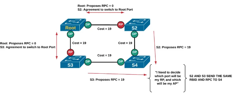
Figure 3.11: RSTP tiebreaker process
which port will become the root port. Because S2 has a lower BID than S3 (due to its lower MAC address), S4 puts its interface attached to S2 as its root port. For each segment, the switch’s interface that contains the superior information is allowed to keep its interface in the designated role and transitions to learning and then the forwarding state.
The final decision made in RSTP is which interfaces need to be blocked so that the spanning tree can be completed. For the example topology, S4 knows that it has a root port that it will forward traffic on, but its interface pointed towards S2 is inferior to the one attached to S2. This is determined, in this situation, by comparing the sender RPC’s of S2 and S4. Because S4 already has a root port, it takes the interface pointing towards S2 and sets it as an alternate port with a discarding state. In the event that S4’s root port should fail, the alternate port, as the name suggests, will take over immediately as the new root port. This process can be seen in Fig. 3.12
Figure 3.12: RSTP blocking process
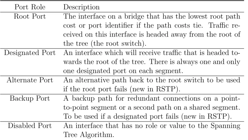
Table 3.1: 802.1w RSTP Port Roles
Port Role Description
Root Port The interface on a bridge that has the lowest root path cost or port identifier if the path costs tie. Traffic re-ceived on this interface is headed away from the root of the tree (the root switch).
Designated Port An interface which will receive traffic that is headed to-wards the root of the tree. There is always one and only one designated port on each segment.
Alternate Port An alternative path back to the root switch to be used if the root port fails (new in RSTP).
Backup Port A backup path for redundant connections on a point-to-point segment or a second path on a shared segment. To be used if a designated port fails (new in RSTP). Disabled Port An interface that has no role or value to the Spanning
[image:43.612.126.523.398.622.2]Table 3.2: 802.1w RSTP Port States
Port State Description
Discarding The interface will not make updates to its Source Address Table (SAT) nor will it forward any frames.
Learning The interface will make updates to its Source Address Table (SAT), but it will not forward any frames.
Prior Work
4.1
RSTP Performance Analysis
The Rapid Spanning Tree Protocol is an IEEE standard [1, 9] and was not born within traditional academia and peer-reviewed publications, but from the IEEE 802.1 working group. As a result, networking device manufacturers took the stan-dards documents that included RSTP specifications and began the process of im-plementing the protocol. This caused any performance studies of the protocol to occur after it had been fully implemented onto network switches, which left re-searchers the choice of testing specific RSTP implementations (such as Cisco‘s, or Open vSwitch in this studies case) or simulating the protocol. With that being said, the networking research communities desire to move beyond RSTP and onto novel, loop-avoidance protocols or replacement solutions resulted in a lack of pure-RSTP
performance studies overall. A literature review of RSTP performance research that is available showed that simulating the protocol was a more popular decision.
Pallos et al. goes on to explain that they built a ring topology with three to seven switches and a partial-meshed topology of eight switches. Each topology had one link broken, and the single test on the partial-meshed topology resulted in a full reconvergence of 60 milliseconds.
4.2
MTP Performance Analysis
In comparison to RSTP, the Meshed Tree Protocol was born out of academic re-search and has begun to go through the process of traditional peer-reviewed rere-search from a team within the Rochester Institute of Technology. Due to the fact that the protocol itself has not fully been standardized by the IEEE, the operation of MTP and its test implementation are still a work-in-progress that has grown and changed over a number of years. At the time of writing, MTP has not attracted attention from major vendors/networking equipment manufacturers to gain support for im-plementations to be written for their products, Cisco and their line of switching products for example.
switches and two loops. The results of the simulations dealt with the latency, upon startup, of the creation of a meshed tree in the case of MTP and a spanning tree in the case of RSTP. MTP outperformed RSTP in regards to the tree creation metrics in this study. Sharma [17] expanded the work on MTP by dedicating a thesis to its properties once again against RSTP. Topologies with 3 switches, 7 switches, and 15 switches were designed for use in OPNET. A number of metrics were defined for RSTP, such as initial convergence time and link failure recovery time. This contrasts MTP, which had only one metric studied, time to reconvergence due to a root bridge failure. The same metric was used as a comparison to RSTP, beating it by several seconds.
Methodology
5.1
Materials
To proceed with the analysis of the performance of MTP against RSTP, a collection of software as well as hardware was acquired or designed. The implementation of MTP used for testing was written in the C programming language and based on properties of the protocol found in its standard [6]. The development of this implementation was completed in a Unix-like environment based on a distribution of the Linux Kernel, for tests on nodes that also run Linux distributions. This software was executed in the user-space of the operating system on the tested nodes and takes advantage of the underlying Linux kernel networking TCP/IP software stack as well as the creation of raw Ethernet II frames to send the PDU. This implementation of MTP is the only one to have been developed at this time, and
has been used exclusively for testing purposes. The RSTP implementation used for testing was the production-level software Open vSwitch (OvS), which functions as an extendable virtual network switch and is available to the public as open source software [14]. OvS, as a fully-featured virtual switch, includes RSTP as an option for loop-avoidance based off its properties found in IEEE 802.1D-2004. The C language was also used to develop OvS and its resulting RSTP functionality. Mirroring the testing done on the MTP implementation, the OvS RSTP implementation testing was completed on systems with a Linux distribution.
5.2
Measurements
A number of metrics were defined to describe the performance of a loop-avoidance protocol. While the initialization of a loop-free switched topology is important and solves the base issue of broadcast radiation, the idea that any computer network will be able to maintain its most efficient state as well as configuration is not a practical solution, as networks can and will fail. This means that critical control protocols such as RSTP and MTP need to be robust and ready for modification or failure at any given point. To account for this need, the core metrics used to analyze the difference in performance between the two protocols was the reconvergence time upon the failure of a network interface and the number of client frames that were lost as a result of the failure and subsequent reconvergence efforts.
Reconvergence time (Broadcast tree):
the final step in the reconvergence process. Different interfaces play different roles within the loop-free topology, thus a number of different recovergence events can occur and change the reconvergence time.
Reconvergence time (Unicast path):
As previously shown in Fig. 3.7, MTP contains separate table entries for the purposes of switching unicast frames as opposed to having to flood broadcast frames along the PVID broadcast tree. RSTP, by forcing unicast traffic onto the broadcast tree, does not have a seperate convergence for unicast traffic. This metric is used to record the reconvergence process by MTP to fix any failures that might occur between two nodes and their unicast path determined by the protocol. It is used when testing unicast frame loss to show the differences in techniques by the two protocols and how the recovery in MTP using VIDs differs from its own per-client-interface entries.
Loss of Client Frames:
caused.
5.3
Procedures
Overview:
Network Time Protocol (NTP) replacement which offers precise time measurements and modifications. The suite of Google time servers was used as the official time servers for all of the nodes, and each node had its clocks correctly configured within a millisecond.
Client Traffic Generation:
Figure 5.1: Traffic Generation Example
Filler was added at the end of each payload as a means of lengthening the frame to the Ethernet MTU, 1500 bytes. Thus, each client frame sent had a total of 1514 bytes (14 bytes for the Ethernet II header). Traffic generation always occurred in one direction, where the source sent to every other client in the event of broadcast frame, or its targeted destination in the event of unicast frames.
Framework Implementation:
Results
6.1
5 Node Topology Results
[image:65.612.112.534.505.578.2]6.1.1
5 Node Topology Data
Table 6.1: 5 Node Results - Topology Reconvergence Averages (sec.)
Test MTP Broadcast RSTP Broadcast MTP Unicast RSTP Unicast Failure 1 2.2764 7.5060 2.1385 7.4096 Failure 2 0.0049 2.8282 2.2358 3.0524 Failure 3 2.6518 6.8654 2.7119 7.0862 Failure 4 0.0025 2.5626 2.1031 2.3870
Table 6.2: 5 Node Results - Client Broadcast Frame Loss Node Failure 1 Failure 2 Failure 3 Failure 4 Client 1 MTP 233 1.6 0 0 Client 1 RSTP 767 20.8 0 0 Client 2 MTP 0 0 0 0 Client 2 RSTP 0 0 0 0 Client 3 MTP 235.8 3.4 262.2 2 Client 3 RSTP 766.8 10.8 628.2 14.8
Client 4 MTP 0 0 0 0 Client 4 RSTP 0 0 0 0
Table 6.3: 5 Node Results - Client Unicast Frame Loss
Test Source Destination Frame Loss (MTP) Frame Loss (RSTP) Failure 1 client 0 client 1 1 907.6
Failure 2 client 0 client 1 495.4 19.8 Failure 3 client 0 client 3 4.6 869.4 Failure 4 client 0 client 3 248.6 17.2
6.1.2
5 Node Topology Discussion
[image:66.612.118.527.333.409.2]MTP this means that the PVID port failed. In both cases, recovery was faster due to immediate failback paths that were be activated. These represent the best-cast scenarios for interface failures due to the short failure detection time. As a result of the short failure detection time, the failure recovery time, the actual act of fixing the topology, contributes to the majority of the (minimal) latency. In a similar fashion, the increase in latency from failures 1 and 3 were due to the downstream interfaces being broken, which represent a designated port in RSTP and a CPVID port in MTP. The downstream switch that no longer has its most efficient path back to the root needs to find a new path back, which requires additional actions. These breaks rely on timeouts, which creates a fixed amount of latency towards failure detection that results in sub-optimal performance when compared to failures 2 and 4. Once the detection has occurred because of the timeout, the failure recovery of the break is comparable with what was seen in failures 2 and 4.
steady around the configured timeout value when considering clients that need to be switched to that node for further forwarding.
6.2
10 Node Topology Results
[image:69.612.110.533.242.328.2]6.2.1
10 Node Topology Data
Table 6.4: 10 Node Results - Topology Reconvergence Averages (Sec.)
Table 6.5: 10 Node Results - Client Broadcast Frame Loss Node Failure 1 Failure 2 Failure 3 Failure 4 Failure 5 Client 1 MTP 573.8 8.4 0 0 0 Client 1 RSTP 785.6 0 0 0 0 Client 2 MTP 0 11.4 0 0 0 Client 2 RSTP 0 22.8 0 0 0 Client 3 MTP 216.6 11.6 0 0 0 Client 3 RSTP 785.6 0 0 0 0 Client 4 MTP 0 14.4 487 1.8 0 Client 4 RSTP 0 13.6 841.6 0 0 Client 5 MTP 217 12.8 11 8.2 0 Client 5 RSTP 785.6 0 0 13.4 0 Client 6 MTP 0 15.2 492.2 1.8 0 Client 6 RSTP 785.6 0 0 0 0 Client 7 MTP 122.8 11.6 428.4 3.2 0 Client 7 RSTP 785.6 0 0 0 0 Client 8 MTP 0 15.8 492.6 1.8 0 Client 8 RSTP 785.6 0 0 0 0 Client 9 MTP 0 15.4 428.4 3 6 Client 9 RSTP 785.6 0 0 0 8.6
Table 6.6: 10 Node Results - Client Unicast Frame Loss
Test Source Destination Frame Loss (MTP) Frame Loss (RSTP) Failure 1 client 0 client 1 0.6 1014.4
Failure 2 client 0 client 4 611.2 12 Failure 3 client 0 client 4 12.6 1035.8 Failure 4 client 0 client 5 531.8 23.2 Failure 5 client 0 client 9 181 14.2
6.2.2
10 Node Topology Discussion
[image:70.612.120.525.482.569.2]for a Hello-timer timeout (the failure detection time) to realize that its CPVID port is dead. Because this timeout is 2 seconds, the resulting convergence connection mimics the behavior of a CPVID interface failure.
6.3
17 Node Topology Results
[image:73.612.110.534.242.328.2]6.3.1
17 Node Topology Data
Table 6.7: 17 Node Results - Topology Reconvergence Averages (Sec.)
Table 6.8: 17 Node Results - Client Broadcast Frame Loss Node Failure 1 Failure 2 Failure 3 Failure 4 Failure 5 node 1 MTP 550 0 5.6 0 0
node 1 RSTP 786 0 0 0 0
node 2 MTP 1.2 4.6 5.6 0 0 node 2 RSTP 0 15.4 0 0 0 node 3 MTP 551.2 0 5.6 14.2 0
node 3 RSTP 786 0 0 0 0
node 4 MTP 1.2 40.4 5.6 11.8 0 node 4 RSTP 0 16.4 0 0 0 node 5 MTP 551.8 0 677 14.2 0 node 5 RSTP 810.2 0 774 0 0 node 6 MTP 1.2 20.8 5.6 16.4 0 node 6 RSTP 0 16.4 0 20 0 node 7 MTP 707.2 0 680 14.2 0 node 7 RSTP 791.6 0 775.4 0 0 node 8 MTP 6.6 21 5.6 18.2 0 node 8 RSTP 0 40.6 0 14.4 0 node 9 MTP 227.4 2.6 238.4 17.8 6.6 node 9 RSTP 0 9 2.2 9.6 11.2
Table 6.9: 17 Node Results - Client Unicast Frame Loss
Test Source Destination Frame Loss (MTP) Frame Loss (RSTP) Failure 1 client 0 client 1 1.4 1065.8
Failure 2 client 0 client 5 778.4 17.6 Failure 3 client 3 client 14 2.4 1067.8 Failure 4 client 0 client 13 727.6 18.8 Failure 5 client 0 client 16 369.4 12.6
6.3.2
17 Node Topology Discussion
[image:74.612.119.526.482.569.2]Conclusion
The Meshed Tree Protocol is a novel contribution to loop-avoidance in switched networks. Due to the widespread use of the Rapid Spanning Tree Protocol, a com-parison between the two was important for the future developments of MTP and how it stacks up to a time-tested protocol that is now showing its age. There are a number of replacement protocols in development by various organizations, but the results of this study help prove that MTP is worthy to be considered as an alternative in the future. Future work on the protocol will be used to bring its implementa-tion into producimplementa-tion environments and into the kernel space of Linux. Addiimplementa-tional work on convergence and recovery operations will be pursed for increased efficiency. Standardization of MTP is also ongoing and will continue to be pursued so that the protocol is more visible to those who may be in need of such a solution or have pursued a similar idea. Furthermore, research work into MTP is planned to continue
[1] “IEEE Standard for Information Technology -Telecommunications and Infor-mation Exchange Between Systems - Local and Metropolitan Area Networks - Common Specifications - Part 3: Media Access Control (MAC) Bridges: Amendment 2 - Rapid Reconfiguration,” IEEE Std 802.1w-2001, 2001.
[2] R. Perlman, D. Eastlake, D. Dutt, S. Gai, and A. Ghanwani, “Routing bridges (rbridges): Base protocol specification,” RFC 6325, RFC Editor, July 2011.
http://www.rfc-editor.org/rfc/rfc6325.txt.
[3] “IEEE Standard for Local and metropolitan area networks–Media Access Con-trol (MAC) Bridges and Virtual Bridged Local Area Networks–Amendment 20: Shortest Path Bridging,” IEEE Std 802.1aq-2012 (Amendment to IEEE Std 802.1Q-2011 as amended by IEEE Std 802.1Qbe-2011, IEEE Std
802.1Qbc-2011, IEEE Std 802.1Qbb-802.1Qbc-2011, IEEE Std 802.1Qaz-802.1Qbc-2011, and IEEE Std
802.1Qbf-2011), 2012.
[4] “IEEE Standards for Local and Metropolitan Area Networks - Amendment to
802.1Q Virtual Bridged Local Area Networks: Multiple Spanning Trees,” IEEE
Std 802.1s-2002 (Amendment to IEEE Std 802.1Q, 1998 Edition), 2002.
[5] M. Berman, J. S. Chase, L. Landweber, A. Nakao, M. Ott, D. Raychaudhuri, R. Ricci, and I. Seskar, “Geni: A federated testbed for innovative network experiments,” Computer Networks, vol. 61, pp. 5 – 23, 2014. Special issue on Future Internet Testbeds Part I.
[6] Standard Contributors, “P1910.1 - standard for meshed tree bridging with loop free forwarding,” 2019.
[7] “IEEE Standard for Local Area Network MAC (Media Access Control) Bridges,” ANSI/IEEE Std 802.1D, 1998 Edition, 1998.
[8] R. Perlman, “An algorithm for distributed computation of a spanning tree in an extended lan,” in Proceedings of the Ninth Symposium on Data
Communi-cations, SIGCOMM ’85, pp. 44–53, 1985.
[9] “IEEE Standard for Local and metropolitan area networks: Media Access Con-trol (MAC) Bridges,” IEEE Std 2004 (Revision of IEEE Std 802.1D-1998), 2004.
[11] R. Pallos, J. Farkas, I. Moldovan, and C. Lukovszki, “Performance of rapid spanning tree protocol in access and metro networks,” in2007 Second
Interna-tional Conference on Access Networks Workshops, pp. 1–8, Aug. 2007.
[12] G. Prytz, “Network recovery time measurements of rstp in an ethernet ring topology,” in 2007 IEEE Conference on Emerging Technologies and Factory
Automation (EFTA 2007), pp. 1247–1253, Sep. 2007.
[13] S. V. P. Soundararajan, “Rstp convergence time calculation for link and root failure on open vswitch (ovs),” Master’s thesis, Rochester Institute of Technol-ogy, 2018.
[14] Linux Foundation, “Open vswitch,” 2019.
[15] N. Shenoy and Y. Pan, “Multi-meshed tree routing for internet manets,” in2005
2nd International Symposium on Wireless Communication Systems, pp. 145–
149, Sep. 2005.
[16] K. Sharma, B. Hartpence, B. Stackpole, D. Johnson, and N. Shenoy, “Meshed tree protocol for faster convergence in switched networks,” in 2014 IARIA
In-ternational Conference on Networking and Services (ICNS), pp. 90–95, April
2014.
[18] R. V. Pillai, “Optimized unicast frame forwarding in meshed tree protocol,” Master’s thesis, Rochester Institute of Technology, 2017.
[19] P. Willis and N. Shenoy, “The evaluation of a meshed tree protocol on the geni testbed,” in 2018 IEEE International Symposium on Local and Metropolitan
Area Networks (LANMAN), pp. 129–130, June 2018.
[20] P. Willis and N. Shenoy, “A meshed tree protocol for loop avoidance in switched networks,” in 2019 International Conference on Computing, Networking and
Communications (ICNC), pp. 303–307, Feb 2019.
[21] J. Forcier, “Paramiko,” 2019.
[22] The Scapy Community, “Scapy,” 2019.