University of Southern Queensland
Faculty of Engineering and Surveying
Investigation of a Variable Ride Height
Suspension for an Automobile
A dissertation submitted by
Mr Joshua Graeme Walton
in fulfilment of the requirements of
Courses ENG4111 and 4112 Research Project
towards the degree of
Bachelor of Mechanical Engineering
ABSTRACT
This dissertation investigates a new way of varying the ride height for a passenger vehicle. It follows the design process from the first step of checking history, background and current development of suspension. Next it looks at building the concept of a new air spring which attempts to maintain a relatively constant pressure while increasing the area over which this pressure is acting. Material and manufacture process selection are conducted for the new concept and a process of vibration analysis for an automobile is undertaken.
University of Southern Queensland
Faculty of Engineering and Surveying
ENG4111 & ENG4112
Research Project
Limitations of Use
The Council of the University of Southern Queensland, its Faculty of Engineering and Surveying, and the staff of the University of Southern Queensland, do not accept any responsibility for the truth, accuracy or completeness of material contained within or associated with this dissertation.
Persons using all or any part of this material do so at their own risk, and not at the risk of the Council of the University of Southern Queensland, its Faculty of Engineering and Surveying or the staff of the University of Southern Queensland.
This dissertation reports an educational exercise and has no purpose or validity beyond this exercise. The sole purpose of the course "Project and Dissertation" is to contribute to the overall education within the student’s chosen degree programme. This document, the associated hardware, software, drawings, and other material set out in the associated appendices should not be used for any other purpose: if they are so used, it is entirely at the risk of the user.
Professor Frank Bullen
CERTIFICATION
I certify that the ideas, designs and experimental work, results, analyses and conclusions set out in this dissertation are entirely my own effort, except where otherwise indicated and acknowledged.
I further certify that the work is original and has not been previously submitted for assessment in any other course or institution, except where specifically stated.
Joshua Graeme Walton
Student Number: 0050026275
______________________________________ Signature
ACKNOWLEDGEMENTS
TABLE OF CONTENTS
Contents
Page
ABSTRACT i
CERTIFICATION iii
ACKNOWLEDGEMENTS iv
LIST OF FIGURES iix
LIST OF TABLES x
LIST OF APPENDICES xi
NOMENCLATURE AND ACRONYMS xii
CHAPTER 1 – INTRODUCTION
1.1Outline of the study 1
1.2Introduction 1
1.3The Problem 2
1.4Research Objectives 3
1.5Conclusions: Chapter 1 4
CHAPTER 2 – LITERATURE REVIEW
2.1 Introduction 5
2.2 Development of Suspension 5
2.3 Height Adjustable Suspension 7
2.4 Motor Vehicle Geometry 11
2.5 Dynamics of a Car 11
CHAPTER 3 – CONCEPT DEVELOPMENT AND DESIGN
3.1 Introduction 17
3.2 The First Idea 17
3.3 The Right Theory 20
3.4 Concept Development 22
3.5 The Final Concept 26
3.6 Adjusting the Concept for Manufacture 28
CHAPTER 4 – MANUFACTURE
4.1 Introduction 30
4.2 Component Separation 30
4.3 Flexible Bag Sections 30
4.4 Rigid Rings 37
4.5 Upper Mount 45
4.6 Lower Mount 46
4.7 Conclusions: Chapter 4 48
CHAPTER 5 – VIBRATION ANALYSIS
5.1 Introduction 50
5.2 Evaluation Method 50
5.3 Theoretical Modelling Methods 52
5.4 Creating a Half-Car Model 53
5.5 Free Vibration Analysis 59
5.7 Conclusions: Chapter 5 70
CHAPTER 6 – CONCLUSIONS
6.1 Introduction 71
6.2 Discussion 71
6.3 Further Research and Recommendations 72
6.4 Summary of Chapter 6 73
APPENDIX A – Project Specification 74
APPENDIX B – freevibrationsolution.m 76
APPENDIX C – AnalysisDriver.m 78
APPENDIX D – halfcarmodel.m 83
APPENDIX E – FourDOFplot.m 85
APPENDIX F – Consequential Effects 89
LIST OF FIGURES
Number
Title
Page
2.3.1 Coil spring height adjustable suspension. 8
2.3.2 Air Springs 9
2.3.3 Hydropneumatic suspension 10
2.5.1 Holden Commodore VS Series 1 Vacationer 12
2.5.2 McPherson strut suspension 13
2.5.3 Solid five point rear axle with Panhard rod 14
2.5.4 Company supplied spring data 14
2.5.5 Company supplied damper data 15
2.5.6 Stabilising bar. 16
3.2.1 Illustrating the varying spring constant 18
3.2.2 The very first concept 18
3.2.3 The inverse relationship between volume and pressure 19
3.3.1 The linear relationship approximation between area and force 21
3.4.1 Early concepts for an air strut 22
3.4.2 Attempts at achieving an area growth via vertical displacement 23
3.4.3 Area growth internally and externally 24
3.4.4 Attempt at volume segregation 25
3.5.1 The final concept expanded and compressed 27
3.5.2 Two cavity illustrations 28
4.4.2.1 Revolved profile of both internal and external rigid rings 44
4.4.2.2 Revolved profile of rough shape. 45
4.5.1 Upper mount 46
4.6.1 Lower mount manufactured by casting 47
4.6.2 Lower mount manufactured by welding 48
5.4.1 Free body diagram for a half-car model. 54
5.4.2 Tyre contact with road. 58
5.6.1 Motion picture of car. 66
5.6.2 Position results for forced vibration 67
5.6.3 Velocity results for forced vibration 68
LIST OF TABLES
Number
Title
Page
4.1 Properties of varying forms of rubber. 33
4.2 Mechanical properties of industrial fibres 36
4.3 Costing for various types of steel, metal and alloy 38
4.4 Corrosion resistance of various steels, metals and alloys 39
4.5 Compatibility between processes and materials 40
LIST OF APPENDICES
Number
Title
Page
A freevibrationsolution.m 74
B AnalysisDriver.m 76
C halfcarmodel.m 81
D FourDOFplot.m 83
NOMENCLATURE AND ACRONYMS
The following abbreviations have been used throughout the test and bibliography:
FBD Free body diagram
DOF Degree of Freedom
mx Mass in kilograms
Ix Second moment of inertia in kilograms per metre squared
kx Spring constant in newtons per metre
cx Damping ratio in newtons per metre squared
φ Angle in degrees
CHAPTER 1
INTRODUCTION
1.1
Outline of the study
This project is focused on modelling and analysing a new variable height suspension system for a passenger car. The project intends to undertake detailed static and dynamic analysis of a new variable height suspension system, model the suspension system and propose a complete design for a particular automobile. This is entirely theoretical and analysis will be computer based due to the time constraints placed on this project.
1.2
Introduction
The cars of today tend to be only made for one purpose. It would be near impossible to find a car that not only caters for a smooth ride over rough roads but can also minimise roll when cornering tightly on smooth roads. Variable ride height suspensions are by no means a new idea, but don’t offer the versatility being pursued in the outcome of this project. Limitations in current systems come about by not catering for a change in spring rate as the car’s height is being altered. The result is a less than optimum solution in a smaller range of running conditions.
Australian’s in general are required to travel massive distances every year over roads that vary greatly in quality. For anyone who enjoys the luxury of a low riding car and the associated handling benefits, they are forced to sacrifice comfort when driving on rough roads. Innovation is required to produce a system that will be able to function in all conditions and for all applications.
Because of the personalised nature of each individual vehicle suspension, this project will only investigate the new system for one model of vehicle. For this project that vehicle will be a 1996 Series I, VS Commodore due to the availability of this vehicle for gaining data to be analysed. Despite the fact only one application will be studied, it will be easy for the same principles and system identified in this project to be applied to any other vehicle. Once the system has been created and testing procedures established, the personalisation of the system for each individual vehicle will be a natural step forward.
At the outset, time will be spent investigating current technology to prevent wasted time spent on covering already developed areas of this research and development. Then with a well rounded view of current innovation, the design and testing of a system to satisfy the aims of this project can be completed with a much stronger sense of direction and in a shorter space of time.
Developing a complete solution requires a wide variety of vibration analyses on the system to be in question. The behaviour and response of the car as it is acted on by the road affects the drivers comfort and ability to navigate different types of roads at varying speeds. This project will seek to simulate the extremes to which suspension in Australia might be made subject to, and furthermore the affects passed onto the driver in each situation. Results for the new suspension method will be compared and contrasted to a set of control results established for a standard suspension system in use today.
It is important that the analysis of vehicle suspension and vibration be sound in its consideration of all factors and variables to ensure sufficient accuracy for the results to be projected directly into the real world. Following the conclusions of this project there may be a desire to continue the development of this idea and produce physical prototypes. Therefore despite this projects immediate theoretical basis, it will be possible for the solution to be taken and put directly into service.
1.3
The Problem
Cars have undergone rapid evolution over the 20th century and during the entire process suspension has been critical to the cars ride and handling. Suspension governs the way in which a car holds on to the road, takes corners and how much road variation is transmitted to the occupants.
ensure a comfortable ride at relatively low speeds. If a car like this were to be driven fast in cornering manoeuvres or rapidly accelerated/decelerated, the driver would notice the car become unstable and begin to pitch and roll. This reaction is a direct result of the suspensions limited functioning capacity purposely intended by the designers. Next take a sports car with low profile tyres and stiff suspension. A car like this is well suited to smooth roads and fast driving but take it outside the city or on an unsealed road and the driver comfort and the cars life span declines rapidly. The general rule in making cars is that they are made for one purpose only and using it beyond that purpose is detrimental to the safety, comfort and life span of the vehicle. My aim is to produce a new way of suspending a car that will allow it to multitask. I want to design a new strut that adjusts between a sports-like ride and a soft cushioning ride. By fitting this strut I want the driver to have the ability to modify the cars height and handling while driving to accommodate such a radical transition as going from racing on smooth track to driving on unsealed roads.
The new struts primary purpose will be to meet the performance demands of users across the board by increasing functionality. Its development will not be constrained by an increase in cost or greater use of power however these factors will rank as highly important throughout the design process. This project is conducted with the recognition that this new strut is by no means an essential improvement but rather a luxury and an after market upgrade. Its viability will depend on the degree to which it succeeds to meet its intended design criteria and at what cost this comes.
1.4
Research Objectives
This project aims at creating a versatile method of suspension capable of adjusting its resting height and spring constant. This suspension must permit the car on which it is installed to enjoy improved, sustainable and successful use over a greater variety of road conditions. The suspension must provide comfort and safety for the driver by dissipating vibrations from the worst of road conditions. In meeting these aims, the specific objectives below are to be pursued:
• Review literature relating to the development and current advancements in suspension technology, particularly in the area of adjustable suspension.
• Develop a method of achieving car height and spring rate adjustment.
• Determine and implement a way of modelling the new system of suspension for analysis purposes
• Develop assessment criteria that can be used to determine the relative success or failure of the suspension system in meeting the project aims.
• Run a full analysis using the chosen method of model taking into account different driving variables such as road condition, car load, and car height.
• Optimise the design concept using the gained results and finalise the design by producing detailed drawings.
1.5
Conclusions: Chapter 1
CHAPTER 2
LITERATURE REVIEW
2.1 Introduction
The movie ‘Hitch’(2005) contains a line spoken by Alex Hitchins:
“You can’t know where you’re going until you know where you’ve been”.
The context in which this statement was said bears no relevance to this project, but the statement itself does. Without a proper review into the literature associated with this problem there is no way of knowing whether the solution developed is simply retracing an already defined path in the history of suspension. This chapter will assist in understanding the background to the problem identified in this dissertation.
2.2 Development of Suspension
Suspension has and always will be one of the most defining aspects of a cars handling, comfort, and safety. The development and progression of the motor car over the last century draws strong parallels to the development of the suspension on which it rides. With cars becoming faster, and a growing expectation for increased comfort and safety, suspension has had to evolve and cater for all these needs.
The Sumerians were the earliest recorded civilisation and yet all those thousands of years ago vehicles were being used and the inherent need for suspension was born. From the ox cart used by the Sumerians came more advanced carriages and chariots. While none of these vehicles at this stage had incorporated suspension they did contain a certain degree of well thought out engineering. The chariots for instance were made as light as possible for increased performance. The wheels were so light that they were removed when the chariot was not in use so that they could not squash into an oval shape. The desire for greater performance and innovation was evident but it would not be until the 8th century that suspension would be born.
century the chains were replaced with leather straps on coaches and then in the 17th century the metal spring came into existence.
The first steel spring was a flat plate and was used on carriages by the French. This led to the leaf spring being created. The leaf spring utilised multiple layers of springs which actually worked to dampen some of the jolts as a result of the friction between each layer. With the advent of this leaf spring the ‘eight springer’ was created in 1804 by a man named Obadiah Elliot. The most revolutionary aspect of this new vehicle was that each of the four wheels was fixed to the carriage via two leaf springs opposed to each other. In the past horse drawn vehicles required a heavy under-carriage below the suspended carriage, where as now with this new design the carriage could be fixed directly to the axles via springs. This meant lighter vehicles capable of greater speed and improved safety.
The coil spring was first patented in 1763 by R. Twedell but didn’t make its entrance into the automobile industry until Daimler used them on their twin cylinder in the late 1800’s. Other means of suspending a car included torsion bars and even early attempts at air suspension. It wasn’t until 1934 that a great deal of car manufacturers started using the coil spring extensively.
Until the late 1800’s springs were mounted on cars with out any deliberate attempt to prevent the continual oscillation that comes from compressing and releasing a spring. A man by the name of J.M.M. Truffault was the first to incorporate a friction device on his motorbike in 1898. This device was later modified and fitted to an Oldsmobile becoming the first automobile shock absorber. It worked simply with two levers hinged together with a rubber pad at the interface and a bolt that could be tightened or loosened. This type of shock absorber could be defined as a friction type absorber. Following this design came the hydraulic shock and the air shock which still have their place in the engineering of today’s cars.
Air suspension was first attempted in 1909 but the system leaked proving it useless. Firestone released their air suspension in 1933 and became the first to do so successfully. The four springs were replaced with air filled bellows supplied by a small compressor. Unfortunately this system proved rather expensive in comparison to conventional springs and even today the use of air springs requires more setup and more cost.
to suspension just a great deal of middle ground where an optimum setting can be achieved between hard and soft suspension.
As long as roads have bumps and ripples, a car will always require a form of suspension and even today development continues in a never ceasing battle to be better, to innovate and to improve.
2.3 Height Adjustable Suspension
Motor vehicles cater for multitudes of people all demanding performance in a vast array of situations. It is not surprising then that standard production line cars sometimes don’t provide the versatility or performance required by an owner. One way in which these aspects of a vehicle can be improved is by including or installing a method of adjusting the ride height. By adjusting the ride height of a vehicle its aerodynamics, economy, handling, vibration response and carrying capacity can all be affected for the better. While very few cars are produced standard with height adjustable suspension, it can be a useful device that some choose to fit after market.
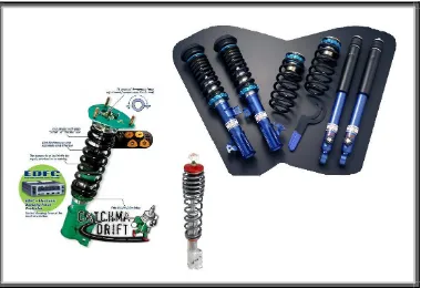
There are three basic forms of height adjustable suspension. The first utilises a standard coil spring although the spring itself may sometimes be far from standard. Systems using coil springs generally require manual adjustment to affect a change in height. Other means of height adjustment utilise either air or a combination of hydraulic fluid and air known as a hydropneumatic suspension.
Figure 2.3.1 – Coil spring height adjustable suspension.
Figure 2.3.2 – Air springs.
The final option for height adjustment is with a hydropneumatic system which combines air/gas and hydraulic fluid, separated by a diaphragm, to spring the vehicle. This system of suspension is typified by the use of spherical reservoirs positioned at the top of each strut on the vehicle. A section view of these reservoirs is shown in Figure 2.3.3 and identifies the two halves of the system. The top half of the system is a gas at pressure and this is separated from a hydraulic fluid by a centrally located diaphragm. Instead of a standard spring and damper making up the strut, a simple piston or syringe is positioned where the normal strut would be positioned. As the suspension is compressed the piston forces hydraulic fluid into the spherical reservoir through a hole which serves as the damper of the system. The size of this hole can be varied to achieve the required damping rate. As the hydraulic fluid is forced into the sphere it compresses the gas in the top section which then acts as a spring and absorbs the force applied by the fluid. Once the suspension is no longer being compressed, the added pressure in the gas forces the fluid to return into the piston.
needed to assist in levelling the car and also help create a stabilising effect similar to that of a stabilising bar. The system must be made quite complex to ensure that the hydraulic fluid is allowed to flow between struts but only when needed. For instance if the front left wheel hits a bump the fluid should be able to flow across to the right front wheel and apply a lifting force to that wheel in order to level the car and detract from the abruptness of the impact. However if this is an open circuit and the fluid is simply allowed to pass at will between the two spheres then during continuous slow cornering the car would gradually fall to the outside of the turn as hydraulic fluid is forced from the outside strut across to the inside. Therefore numerous valves and additional spheres are used within the circuit to make the hydraulic fluid perform similar tasks to mechanical components in a conventional suspension system.
Figure 2.3.3 – Hydropneumatic suspension.
The system of hydropneumatic suspension is one of substantial complexity but does provide a very comfortable ride. One of the drawbacks of this design is that in time there may be issues with hydraulic leaks and possibly pump failures that could be messy and costly to fix.
2.4 Motor Vehicle Geometry
By definition the suspension of a car includes not only the strut but also the arm(s) by which the strut and wheel are attached to the car. Early types of suspension suffered road holding problems whenever the cars height changed over bumps or around corners. This was caused by the suspension arm altering the wheels camber and hence reducing the contact area of the tyre. Modern day suspensions use arm configurations that maintain the camber as the cars height above the road changes. This means that changing the height of the car with a new strut will not adversely affect the contact area of the tyre because the height variation intended in this investigation will be within the manufacturers own limits of normal suspension movement. Many variations of suspension arms exist however because these hold no relevance to the design of this new spring, they need not be explored further.
2.5 Dynamics of a Car
This project aims at discovering an effective alternate means of suspending a car. In order to determine the effectiveness of any new suspension system there must first be a method available to test and compare the suspension to real world and existing suspensions. It would be impossible to evaluate this new method for all models of cars and still remain within the scope of this project. A more realistic approach is to select one type of car, then model the suspension to only suit that motor vehicle. Then by running tests on both the existing suspension and the new suspension without changing the geometry or basic constraints of the car, a result for effectiveness can be achieved.
Figure 2.5.1 – Holden Commodore VS Series 1 Vacationer.
The suspension beneath this model of Holden Commodore is made up of:
• Front
… McPherson strut
… Wet sleeve shock absorber
… Direct acting stabiliser
… Progressive rate coil springs
• Rear
… Five Link Live Axle
… Trailing arms
… Panhard rod
… Progressive rate coil springs
… Stabiliser bar
it transmits much more vibration and road noise to the body of the car than other forms of suspension.
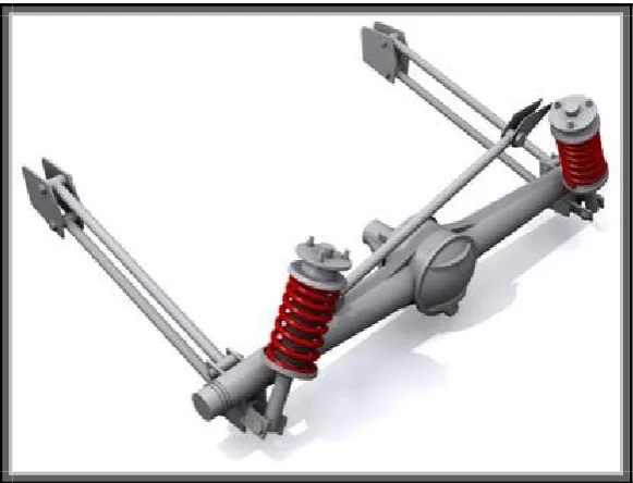
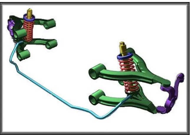
Figure 2.5.2 – McPherson strut suspension.
Figure 2.5.3 – Solid five point rear axle with Panhard rod.
[image:27.595.158.449.112.334.2]The progressive rate coil springs are almost impossible to model accurately without an equation being supplied by the manufacturer. An attempt was made to obtain the spring rates from Holden but they could not be procured. Fortunately data for a Holden Commodore was found within the thesis work of Lars Svedung which he himself gained directly from the Holden Motor Company. The spring rate is said to vary from 19-23 N/mm and can be approximated with a constant value of 21.6 N/mm. A graph shown in Figure 2.5.4 shows data supplied by the company for the spring rate.
Along with data for the variable spring rate came values for the damping coefficients of Holden’s wet sleeve shock absorber. A plot in Figure 2.5.5 shows experimental values of the damping force. As is stated in the figure, the damping coefficient can be approximated with a two standard values. The first value is for compression and is equal to 0.2 N/(m/s) while the second value for extension is 1.4 N/(m/s).
Figure 2.5.5 – Company supplied damper data.
Figure 2.5.6 – Stabilising bar.
In the mechanics of the suspension of this Holden Commodore all these components work together and are critical to the performance and handling of the car. Understanding the physical makeup of this suspension can provide the basis for a sound theoretical investigation and analysis of this suspension.
2.6 Conclusions: Chapter 2
CHAPTER 3
CONCEPT DEVELOPMENT AND DESIGN
3.1 Introduction
Every product, invention or innovation began with a single idea. At some point in time, in some place, in one persons head, an idea came to life and sparked a process of development. No product we use in this modern age ever came into being without time and effort spent in turning an idea into a viable reality. Even the biggest or most complex projects started with an idea and were slowly unfolded to build an accurate picture of how the idea might be brought into existence. This chapter will follow the process of development for the variable ride height suspension from its initial idea through until the aims and objectives have been achieved with a viable solution.
3.2 The First Idea
Many new ideas are born from a perceived need and in this case the same is true. Existing suspension systems successfully provide the ability to adjust car ride height but do not in the same act succeed in varying the spring rate. As well as this the height adjustment on existing units is not a simple operation but instead involves time and effort. The initiation of the idea for this investigation began with the desire to create an adjustable spring that would change its spring constant by itself as its open height was varied. (See Figure 3.2.1) By adjusting the spring rate with the open height, the closed reaction force of the spring can be kept the same and hence prevent a car from bottoming out.
The starting point for innovation was considering whether existing designs could be furthered to include better automation in their adjustment capabilities. For instance in systems where an adjustable mechanical screw is used to move the lower spring mount further down the strut and effectively lower the vehicle. The adjusting screw could be made to operate via electrical motor or servo activated remotely from the cabin. This function combined with the existing remote shock adjustment would allow the entire system to be adjusted easily. However the size of motor or servo needed to move the spring base would be much too large to be deemed viable for cost, space and power consumption reasons. Other methods of adjusting a steel spring were not considered with any weight due to the complexity of the design that would be needed.
Figure 3.2.1 – Illustrating the varying spring constant.
pressure and area. Take any cylinder of any diameter with a slide. The cavity is sealed and the pressure in the cylinder is atmospheric. So we know that as this cylinder is allowed to compress, the amount of the air inside does not change. As the slide compresses the air, the pressure doubles every time the volume halves. Therefore it is virtually impossible for the slide to reach the bottom of the cylinder because the pressure would be infinite.
[image:31.595.141.463.500.664.2]Again take the same cylinder but position the slide at the middle of the cylinder and at this point make the pressure atmospheric. From this point seal the amount of air in the cylinder and begin compressing the volume. As the slide moves down the pressure increases similarly to the first situation except the pressures are scaled over a shorter distance. In this situation the slide will again never reach the bottom of the cylinder because the pressure would have to be infinite. This principle is illustrated in Figure 3.2.2 as a closed circuit that could simply circulate air from the top of the cylinder to the bottom and hence change the position at which the slide was comfortable to be at rest.
Figure 3.2.3 –The inverse relationship between volume and pressure.
3.3 The Right Theory
Achieving great adjustment in this suspension had to come about by the use of air. Air provides an easy means of adjustment by simply modifying pressure or volume through hoses, valves and pumps. Despite the inability of an air cylinder to perform the required job, the use of air began to be explored further with an aim to convert the inverse relationship of the air and pressure into a linear relationship between some other two variables.
A simple look at the gas equation (3.1) proves that unless this device can alter the density or temperature rapidly enough to account for the changes in volume then no linear relationship can be found. The gas equation states that the pressure in a vessel will be equal to the product of the density, gas constant and temperature all divided by volume of the vessel.
P=ρARAT
V
fffffffffffffffffffffff (3.1)
Instead of manipulating the gas a new method of adjusting the force of the spring had to be found. By analysing the basic formula for pressure (3.2) an option was discovered. This equation states the pressure is equal to force divided by area.
P=F A
fffff (3.2)
By transferring the area across to the other side of the equation it becomes an equation for force and states that force is equal to the pressure multiplied by the area.
F=PAA (3.3)
When comparing this with the general spring force equation (3.4) which states that the force is equal to the spring constant multiplied by the deflection of the spring a similarity is observed.
F=kAx (3.4)
By choosing to hold the pressure constant as (k) and only vary the area linearly as a function of height (z), the equation will be transformed into a spring equation with a linear spring constant.
The assumptions made to achieve this spring equation do work nicely but now need justifying rationally. For instance maintaining pressure may not be possible over the entire range of compaction involved with a linear spring. Also increasing the area linearly with respect to height variations may be a difficult feat to achieve. Less pressure variation can be achieved by not altering the volume of a chamber significantly during operation. This means however that the chamber volume needs to be larger in order to decrease the percentage volume made up by the cavity in the spring. Having realised zero pressure variation to be an impossible goal, the assumption was made that during complete compaction of the spring the volume change may be able to be kept to half. Therefore according to equation (3.5) the assumed pressure increase over the full length of operation would be twofold. If the linear area increase could be achieved, the force to vertical displacement graph (Figure 3.3.1) would approximate a straight line and hence a linear spring constant. From this graph the inverse relationship can be seen to have its affect, however the graph remains flat enough to allow an approximate straight line of best fit. This graph proves the theory and made possible the continued development of this idea.
Figure 3.3.1 –The linear relationship approximation between area and force.
Traditionally the air bag suspensions in use today are of a cylindrical construction. To achieve an area increase during compaction of the spring a cylindrical bag was considered. With the area growing externally from an initial radius r1 by an amount ∆r the relationship for linking area to radius is found to
∆A= πA 2Ar
1A∆r
b c
+ ∆r2
D E
(3.6)
This is not a linear relationship thanks to the squared terms, however by attempting an increase in area both internally and externally from a circle of radius r1 a new relationship can be found to be:
∆A=4AπAr1A∆r (3.7)
This relationship is linear and means if the system to be designed can increase area internally and externally it will have a good approximation to a standard spring constant.
3.4 Concept Development
[image:35.595.109.492.463.701.2]While developing the theory for this investigation a parallel process of developing multiple concept ideas ran with it. These existed as mental pictures and sketches right from the inception of this investigation. Some of these concepts were given thought and created before the theory was fully understood, while others were developed after realising the true goal of this design. As a result most of the initial concepts hold no technical value in the build up of theory and understanding for this investigation. However whether technically relevant or irrelevant to the final solution, all these concepts help complete the picture of the mental process of this design.
Some of the earliest concepts as seen in Figure 3.4.1 were based around creating some way of ensuring the air bag could prevent the car from bottoming out during operation. These ideas allowed the normal operation of the of the air bag as it rolls itself up and down a vertical column but created sudden stops where the air bag be squashed against and not allowed to roll any further. The increased area acted on by the bag would prevent further vertical deflection of the strut. In operation this method was thought to do the job by allowing the operator to lower the vehicle to any height and still remain assured that the car could not reach the limit of its travel. In a situation where the car might be used for track racing the vehicle could be lowered right down to the stop and enjoy a vast stiffening of the suspension as a result. The chances of this system accommodating the huge variations in required ride height, handling and road conditions without causing discomfort to the passengers seemed very slim. The idea was abandoned as the thought process was developed further.
Figure 3.4.2 –Attempts at achieving an area growth via vertical displacement.
Another problem existed in the large bag section and its ability to hold its shape under high levels of pressure. In true operation the shape of the bag could not be expected to look as idealist as shown in these sketches. Finally these designs sought the need to seal the central shaft at some point along a sliding surface to prevent air leaks. Considering the number of times the seal would have to slide up and down the shaft in its lifetime it appeared completely impractical to assume the strut would sustain an air tight seal for even a short period of time.
Figure 3.4.3 –Area growth internally and externally.
It was at this point in the design stage that the need to increase the area internally and externally was realised. Not only did this cater for the need to increase the area linearly in relation to the height but it was also considered that a completely air tight seal could be achieved with this new method. On top of these two advantages was another positive of being able to support the bag on the central shaft at the breaks in the sections over its entire length.
ballooning out and taking up too much space in the wheel well of the vehicle. These initial concepts for achieving internal and external area growth used a thick wire ring to simply restrict the bags expansion at certain positions. The rubber not in direct contact with the rings would then only be affected by pressure and could naturally balloon out but only to a limit imposed by the size of the sections. As the strut is compacted the individual sections would squash down on top of each other and create an increase in area varying with height. It was decided that in this design the area increase could not be controlled well enough. This was evident by considering the way in which the rubber would tend to balloon and how that would affect the sections squashing together. There were concerns that the area would not increase at a constant rate and create an unpredictable reaction force from the strut.
Figure 3.4.4 –Attempt at volume segregation.
This would not be easy to protect during operation and may be a cause of concern for reliability.
The positive taken from the design in Figure 3.4.4 is the shape of the formers. Previous concepts displayed in Figure 3.4.3 have positive attributes associated with the single reservoir and having a path for rapid air flow down through the gap between the internal flexible layer and the external flexible layer. Both these concepts have the advantage of locating the bag on the central rod and allowing the bag to be designed to fit within any size of cavity. These positives were major contributors in advancing the design towards completion and to a point where all the objectives and aims could be met.
3.5 The Final Concept
The last step in the production of a solution to this problem came about through a combination of ideas developed in many of the initial concepts. The final concept is shown in Figure 3.5.1 and is made up of three basic components. The first of these is the rubber bag or reservoir which is shaped to have internal and external ribs. Helping keep these ribs defined under pressure and also provide a surface for the bag to be squashed upon during compaction are internal and external steel rings. These rings are sloped to achieve approximately ninety degrees of angle between the exposed surface of the ring and the reservoir and provide a mirror to the reservoir with respect to the horizontal plane. This angle is thought to help the reservoir be laid out upon the rings uniformly during compaction due to the way the bags shape will follow the rings when rolled down them. By keeping all angles with in the structure identical the spring can be compressed to a very small percentage of its open height.
Figure 3.5.1 – The final concept expanded and compressed.
Figure 3.5.2 – Two cavity illustrations.
This concept still requires some thought to bring it to a stage where it can be manufactured but it is successful at this stage in the way it meets the objectives of this investigation. The sloping rings on the outside will prevent any foreign material from gathering on or in the spring. Also the shape of this final solution stands it in good stead for being able to replace existing steel springs of any shape or size. From this point on the process of concept development ends and the design can be carried forth into more processes that pave the way for this system to be put into production.
3.6 Adjusting the Concept for Manufacture
While the theory of how this spring will operate is logical, the design depicted in these concepts does not make sense from a manufacturing standpoint. This concept needs modifications that do not alter the way in which it operates but make it possible to manufacture and assemble.
bag as it is now. To solve this problem there are two possible solutions. Firstly the internal rings could be integrated into the rubber bag from the time of manufacture. If this was at all possible it would certainly require a difficult and complex manufacturing process. The second solution is to split the flexible rubber bag into smaller sections as shown in Figure 3.6.1 and these will then become joined onto the rings during assembly. These smaller sections would be identical and could mean less setup for tooling but the sealing of the sections would be critical to making this design work. If the rubber were joined to the rings via a crimping action and vulcanising, the seal should stand the test of time. The picture shown in Figure 3.6.1 shows the crimping action on the rings as having been closed. The rings would be manufactured with the clamping jaw open so the rubber sections can be inserted and vulcanised to the inside of the jaw and then the jaw can be squashed closed over the rubber.
Figure 3.6.1 – Individual joined sections of flexible rubber.
CHAPTER 4
MANUFACTURE
4.1 Introduction
The design established in the previous chapter has been developed to accomplish the functional requirements of the problem. This chapter will carry on the design process and define the manufacturing processes involved in effectively, economically and simply making the theoretical design into a physical reality. Multiple options for manufacture will be explored before selecting the most suitable process for this specific situation. If necessary the design may undergo changes to allow for a more favourable manufacturing cycle.
4.2 Component Separation
In order to define manufacturing processes and materials for the design it must be split into its separate parts that can be manufactured individually and then assembled. The overall design for the spring has been split up into the following components.
• Flexible Bag Sections
• Shaping Rings
• Upper mount
• Lower mount
The sections that follow from here will examine each of these parts individually to determine the most appropriate material and manufacturing processes.
4.3 Flexible Bag Sections
As seen in the previous chapter, the bag is made up of numerous sections of flexible material shaped to form ribs that must be joined and sealed to the rigid rings creating one long compactable spring. These flexible pieces will be subject to continual distortion and tension as the bag is compacted. As well as this the bag will be exposed to forces of nature that will seek to minimise its life span. The finished product must be able to:
• Withstand the tension it experiences from the internal pressure.
• Resist degrading when exposed to UV light.
• Be attached and sealed to other materials.
• Be cost effective.
The shapes of these flexible sections pose extra difficulty in manufacturing. While selecting a suitable material may seem a simple task, the way in which that material may be worked into the shape require complicates the matter. The solution to this manufacturing problem must be found with a combined look into materials and which respective forming operations are suitable for both the material and the finished product being sought.
A quick glance at any air suspension system from their inception up until this day will prove the fact that rubber is the common material used in flexible bag situations. There are a number of reasons for its prolific use. Rubber can be moulded, extruded and formed into many different shapes and then cured to maintain that initial shape. Rubber can be reinforced with fibres and has excellent ability to bond to various different fibre materials. Rubber can also be bonded or in effect glued to hard surfaces. The stiffness, strength and stability of the rubber may be manipulated to suit a specific service application by varying the constituents that make up the rubber. Rubbers ability to serve in a situation where sealing and flexibility are essential makes it the primary candidate for use in flexible bag suspensions. Selecting the right type of rubber for this particular realm of service will require a well rounded understanding of rubber in general.
4.3.1 Rubber Technology
Rubber was originally sourced from trees until the 1900’s when innovation and the introduction of the motor vehicle saw the need and consequently the first supply of synthetic rubber. At present very little natural rubber is used due to the lack of supply and its unreliable properties. Instead synthetic rubber offers consistency and predictability as well as a variety of properties depending on where the rubber might be used.
Rubber is a polymer of isoprene and is made by firstly producing monomers and then putting them through a process of polymerisation to form rubber. The chemical definition and composition of rubber is known and can be found in the book ‘Rubber Technology and Manufacture’ (1971). Deeper insight into the chemical aspects of rubber is beyond the scope of this study and will not be explored further here. Bearing greater relevance to this study is the physical properties of rubber and having a broad understanding of rubber composition and its affect on properties.
and vulcanising rubber. This meant rubber was always tacky and had very little strength and needed to be coated in powders to cover the sticky surface of the rubber. It was perhaps by accident and because of this method of coating that vulcanising was discovered to occur when the rubber was coated with sulphur and heated. Instead of the material being sticky it transformed into an elastic and tough material that could not be dissolved in solvents. From this discovery rubber became highly useful and continued to prove its value as the development of additives further improved its properties.
Rubber additives consist of accelerators, fillers, plasticisers, softeners and extenders. Accelerators assist in the rapid curing of rubber. Natural rubber tends to cure more quickly than synthetic rubber so accelerators are generally added to the synthetic rubber to bring its curing time in line with natural rubber. Fillers cover a wide range of additives and can be included in the rubber mix for many purposes such as:
• Reinforcing
• Colouring
• Adding Bulk
• Texturing
• Modifying rates of friction and wear
• Creating UV Stability
• Stiffening
• Increasing Durability
• Heat Resistance
Table 4.1 – Properties of varying forms of rubber.
Methods of manufacturing rubber components include the following processes:
• Extruding
… Results in long lengths of various shapes. Some shapes are simple while others can be complex extrusions for use in specific applications like window trim.
• Calendering
… Creates rubber in sheet form by passing it through series of rollers. This method can be used to incorporate textiles into the flat rubber sheet by rolling textile and rubber between the same rollers.
• Solvent Dispersion
… Spreads rubber over textile by scraping a rubber dough across a sheet with a knife edge then evaporating the solvent and curing the left over rubber.
• Moulding
… Used to form items of required shapes in moulds similar to metal casting.
• Bonding
… Attaching rubber to foreign material such as metals to form composite products. This is usually performed with a process of vulcanisation.
4.3.2 Material Selection
Having acquired an understanding of the way rubber has evolved, is composed and is produced, the choice must be made as to which grade of rubber should be used for this specific application. The comparisons made in figure…give a very good overview of properties relevant to the application intended for its service. When comparing the materials a number of different forms of rubber seemed fitting. Natural rubber was ruled out immediately due to its unreliability and variability. Of the other rubbers, the properties found to have greatest weighting in this decision in order of importance were:
• Permeability to Gases
… Needed to ensure that no air from within the bag will be likely to leak through the rubber and cause a decrease in car height.
• Tensile Strength
• Adhesion to Metal
… Needed to ensure adequate hold and seal between the bag sections and the rigid rings. This part of the design is most susceptible to failure and must be treated with care.
• Resistance to Chemicals and Harsh Environment
… Needed to ensure the rubber is stable when exposed to oil, fuel, sunlight, water and heat.
• Abrasion Resistance
… Needed to ensure the bag is not likely to wear itself away in the action of compressing and expanding during its lifetime.
Assessing the permeability to gases helped narrow the choice of rubber to three possibilities including Butyl, Neoprene, and Hypalon. Further consideration of the tensile strength ruled out Butyl rubber and left only two options. Of these two forms of rubber the decision between the two was quite difficult. However Neoprene was found to be the most suitable material for due to its greater resilience or rebound. In an application where the rubber will continually be flexed and placed under varying stress it is important the rubber is not affected adversely by this motion but instead is able to retain its original form. Neoprene also offers excellent adhesion to metal, excellent resistance to all environmental considerations that may be of concern and finally it has excellent abrasion resistance.
Specific Strength Specific Modulus
Material Density
(g/cm3)
Strength
(Kgf/mm2)
(cm x 106) (g/den.)
Modulus
(kgf/mm2)
(cm x 106) (g/den.)
Rubber (tread) 1.1 2 0.19 0.2 0.7 0.062 0.1
Silk 1.25 60 4.6 5 350 27.5 30
Cotton 1.54 70 4.6 5 1000 62.5 70
Rayon (dry) 1.52 70 4.6 5 1900 12.5 140
Nylon 1.14 90 8.1 9 500 38 40
Polyester 1.40 110 8.1 9 1100 76 90
Polyvinylalcohol 1.28 100 8.1 9 1600 125 120
Polypropylene 0.92 70 8.1 9 700 76 85
Glass 2.56 350 13.7 15 7500 280 320
Steel 7.8 280 3.8 4 21000 280 300
[image:49.595.121.476.111.452.2]Carbon Fibre 1.95 210 11.2 12 42000 2150 2400
Table 4.2 – Mechanical properties of industrial fibres.
4.3.3 Manufacturing Process Selection
The sections of flexible bag pose an interesting manufacturing challenge. The odd shape and the circular nature will mean that custom tooling will need to be produced.
To gain the correct shape of these sections with the reinforcing sandwiched in the middle of rubber layers, the textile will firstly need to be custom woven into the required shape. If a standard fabric in sheet form was used, it would need to be cut and rejoined in multiple sections and would mean a sacrifice in strength. The best option is to manufacture three different pieces of woven fabric, for the inside sections, the outside sections and the top piece to join the inside rings to the outside rings. Custom woven sections will have continuous fibre and can be run through a series of shaped rollers for coating with rubber.
textile and press rubber into the fabric the rollers would create varying friction factors as they rolled together which would give varying degrees of adhesion. The best option for coating the fabric is via spreading. The profiled fabric will be spun by two sets of rollers creating a tight section of the fabric where a knife can be run against a flat surface to spread solvent thinned neoprene rubber across the fabric. This process will need to be done once for the inner coating and once for the outer coating. Following this the section of composite material can be heated and cured for a short period of time.
While this whole process will be extremely costly to set up, the benefit of ensuring the flexible sections are manufactured correctly is well worthwhile. Assuming this system is viable and begins mass production, the cost of tooling will become far outweighed by the efficiency and reliability of the process.
4.4 Rigid Rings
This component of the mechanism plays a number of important roles in the functioning of the system. The rings primary purpose is to hold the shape of the bag and by the angle of its faces must define the rate of area increase as the bag is compressed. The rings also join together the small sections of flexible bag to produce one continuous cavity and must therefore give adequate sealing on the sections of flexible bag. In doing these things the rings should also:
•
Minimise or negate any wear of the bag.•
Be capable of withstanding degradation in harsh environments.•
Have adequate strength within the expected range of loading conditions.•
Achieve all these objectives with as little cost as possible.4.4.1 Material Selection
appropriate material the following tables have been extracted from various texts to allow a comparison to be made between common steels, metals and alloys.
Density Cost/tonne Relative Cost/m3 Relative
Material
kg/m3 $/tonne $/tonne $/m3 $/m3
Carbon Steel 7820 1375 1 10752 1,0
Alloy Steels 7820 2075 1,51 16225 1,5
Cast Iron 7225 2075 1,51 14990 1,4
Stainless Steel 7780 11125 8,1 86552 8,0
Aluminium/alloys 2700 5550 4,0 14985 1,4
Copper /Alloys 8900 13875 10,1 123487 11,5
Zinc alloys 7100 5550 4,0 39405 3,7
Magnesium /alloys 1800 10000 7,3 18000 1,8
Titanium /alloys 4500 42500 30,9 191250 17,4
[image:51.595.118.476.180.494.2]Nickel alloys 8900 45000 32,7 400500 36,8
Table 4.3 – Costing for various types of steel, metal and alloy.
The table above should not be trusted as an accurate source of market price. Metal prices are always changing and would need to be confirmed just prior to purchase so as to achieve an accurate price estimate. However this table does provide a good price level comparison which should be accurate given any fluctuations in market price.
against one another to ensure a great deal of extra money is not being spent for little or no increase in physical properties.
Fresh Water Sea Water Air
Metal
Static/Turb Static/Turb City/Indust
Grey Cast Iron-
Plain or Low Alloy 4/3 4/3 3
Cast Iron Ni_Resist.
(14% Ni, 7% Cu, 2% Cr bal Fe) 5/5 5/5 4
Ductile Iron Ni_Resist.
(24 % Ni, bal Fe) 5/5 5/5 4
Mild Steel- Low Alloy steels 4/3 4/2 3
Stainless Steel Ferritic
(17% Cro) 4/6 1/4 3
Stainless Steel Austenitic
(18% Cro ,8% Ni ) 6/6 2/5 4
Stainless Steel Austenitic
(18% Cro 12% Ni, 2.5% Mo ) 6/6 3/5 6
Stainless Steel Austenitic
(20% Cro 29% Ni, 2.5% Mo,3.5% Cu ) 6/6 4/6 6
Copper Nickel alloys
(Up to 30% Ni) 6/6 6/6 5
Nickel Commercial
(99% Ni) 3/5 6/6 4
Aluminium Brass 6/6 4/5 5
Bronze
(88% Cu,5% Sn,5% Ni,2% Zn) 6/6 5/5 5
Aluminium Alloys 4/5 0-5/4 5
[image:52.595.116.481.164.568.2]Titanium 6/6 6/6 6
Table 4.4 – Corrosion resistance of various steels, metals and alloys
The table shown here gives a rating for how affective various metals are at resisting corrosion in specific environments. The scale of ratings begins at zero and designates the metal is unsuitable for a specific application. The best rating is six and designates a metal is excellent for service in the indicated environment.
turbulent fluid are given in the table however for this process of material selection the corrosive fluid is assumed to be static. Reasonable corrosive resistance in these solid rings is a requirement. Selecting a material that can provide absolute corrosive resistance would ensure greatest longetivity of the system but may not be possible due to costs.
Material C a s t Ir o n C a rb o n S te e l A llo y S te e l S ta in le s s S te e l A lu m in iu m a n d A llo y s C o p p e r a n d A llo y s Z in c a n d A llo y s M a g n e s iu m a n d A llo y s T it a n iu m a n d A llo y s N ic k e l a n d A llo y s R e fr a c to ry M e ta ls Sand Casting Investment Casting Die Casting Impact Extrusion Cold Heading
Closed Die Forging
Powder Metal Processing
Hot Extrusion
Rotary Swaging
Machining (from stock)
ECM
EDM
[image:53.595.118.480.207.651.2]Sheet Metal (stamp/bend)
Table 4.5 – Compatibility between processes and materials
performed on a material. Grey squares indicate the process is not commonly used on a specific material but does not rule out its use. Finally the black squares indicate the process is unsuitable for the material designated.
The solid rings for this air spring will need to eventually become a mass produced item. Not only will the system be produced on a production line but each spring assembly will require multiples of these rings. For this purpose the manufacturing processes chosen may require significant tooling and this can be justified in the long term.
Yield Stress Ultimate Stress Material
(MPa) (MPa)
Elongation (%)
Carbon Steel 350 520 30
Alloy Steels 290 415 24
Cast Iron 350 450 15
Stainless Steel 200 500 40
Aluminium/alloys 90 150 12
Copper /Alloys 350 551 50
Zinc alloys 200 300 7
Magnesium /alloys 120 200 7
Titanium /alloys 140 240 54
[image:54.595.168.428.261.575.2]Nickel alloys 860 1000 20
Table 4.6 – Strength values for various types of steel, metal and alloy.
This table shows the ultimate or tensile stress, yield stress and percentage elongation before failure for some common metals. The strength required by these rings is unknown at present but can be calculated easily given that:
•
Maximum load per strut is 500 kg.•
The stress in the rings can be approximated by evaluating the hoop stress as if the rings were a part of a cylindrical pressure vessel. This assumption will not be entirely accurate so the stress will be increased by a factor two. The increase is necessary because the rings are not closed pressure vessels and because of this they cannot be expected to have the same rigidity or strength.Now the smallest area on which the spring can apply its pressure is when it is fully extended and the bag has not been rolled out upon the rings. At this point area A is equal to the area contained by the external radius ro minus the
area contained by the internal radius ri.
ro=56.5mm=0.0565m
ri=38.5mm=0.0385m
#A= πb Aro2c@ πAr
i
2
b c
(4.1)
A=5371mm2=0.005371m2
The pressure within the spring can be calculated with equation (4.2):
P=F
A
fffff (4.2)
#P= 5000N
0.005371m2
ffffffffffffffffffffffffffffffffffffffff
P=931kPa
Now the formula for calculating hoop stress is:
σh=PAr t
fffffffffffff (4.3)
Where P is the pressure of the cylindrical vessel, r is the radius of the cylinder, and t is the thickness of the wall. The radius and thickness are taken off the final design for the rigid rings and the values are measured at the outermost point of the external ring. This position has been assumed to be susceptible to the most stress.
r=83mm=0.083m
#σh=931000A0.083
0.004
ffffffffffffffffffffffffffffffffffffffffffffff
#σh=19.3MPa
After taking into account the double factor for inaccuracies of the hoop stress model and also apply a factor of safety of three, the required yield stress of this rigid ring material is found to be:
σyield= σhA 2times inaccuracy factor
b c
Ab3times safety factorc (4.4)
σyield=115.8MPa
Therefore when using the Table 4.6 the smallest allowable yield stress for selecting a material is 115.8 Mega Pascals.
All the tables above can now be compared and contrasted with each other to select the most appropriate material. These tables define the most important aspects for our material selection and cover a wide range of possibly appropriate material.
The material chosen after a process of elimination is alloy steel. The reason for this choice is heavily weighted on the price. A step up from alloy steel to a stainless steel will see the price increase five fold. Also in many cases for stainless steels the corrosion resistance in static salt water is not significantly better than alloy steel. The strength of alloy steel is very sufficient for this application and it can be put through every manufacturing process we might be inclined to use. Other steels that were considered were the stainless steels and copper alloys. These two materials were compatible with all the manufacturing processes we desired and copper alloys in particular had exceptional corrosive resistance. However both these materials would have required much more cost and were therefore deemed unacceptable. Although alloy steel does not have perfect corrosion resistance it should provide enough resistance to ensure a long life in this application and prevent wear of the flexible rubber bag. When this system is physically tested the corrosion resistance can be observed and the material can be upgraded to stainless steel or copper alloy if needed. For now though the cost effectiveness of the alloy steel make it the best option for the rigid rings.
4.4.2 Manufacturing Process Selection
finished smoothly. On top of this the shape of them as shown in Figure 4.4.2.1 means that simply machining them out of a billet will create far too much waste. The figure shows two sets of jaws which represent both the manufactured shape (solid line) and the squashed jaw position (dashed line) after the rubber has been inserted. Upon consideration it is evident that no single process can be used to manufacture these rings. Some combination of processes will be needed to bring these rings to a point where they meet the desired specifications for this design. If there are to be multiple processes used it seems obvious that the first process will be used to form the basic shape while the second process will create the required surface finish as well as the detail.
Figure 4.4.2.1 – Revolved profile of both internal and external rigid rings.
Once the hot material has been stamped for the first time and the shape has been made the flash can be removed roughly in a second stamping process. Further removal of flash and cleaning will need to be performed in the second process.
Figure 4.4.2.2 – Revolved profile of rough shape.
Once forging of these rings have been completed the jaws must be cut into the rough shape and the whole part must be cleaned and smoothed. Given these rings are circular the most simple option for completing this step of manufacture is turning these features into the rings. Both internal and external rings may be held in a machine centre while the necessary cuts are made with a tooling point. Once the cuts have been made then the whole disk can be smoothed with a fine grinding operation also performed in a machine centre.
The processes selected to manufacture the rigid rings have been selected out of necessity. The rings have been designed to perform a task and could not be modified in any way to allow a more straight forward manufacturing process. While in many cases a part may be designed with manufacturing in mind this was not the case with these rings. Despite that fact the manufacturing processes assigned to these disks should allow good repeatability and cost effectiveness when put into a production line.
4.5 Upper Mount
The final design of the top mount is shown in Figure 4.5.1 and has been created from two pieces that will be stitch welded together. The material for the upper mount will be alloy steel to match the material used in making the rigid rings. As with the rigid rings, the lower piece of this mound will be created by hot forging a billet of material and then grinding the surface smooth. The upper section of this mount can be manufactured by stamping a disc of flat sheet that has been laser cut. The stamping will require a former to be manufactured but this process need not be completed with any great form of accuracy. The only concern for the upper section is that the holes are consistently positioned at the right pitch circle diameter.
Figure 4.5.1 – Upper mount.
The hole in the middle of the forged component makes provision for the shock absorber shaft to protrude through this plate and also be attached to the car.
This top mount is n