City, University of London Institutional Repository
Citation
:
Atsonios, K., Violidakis, I., Agraniotis, M., Grammelis, P., Nikolopoulos, N. and
Kakaras, E. (2015). Thermodynamic analysis and comparison of retrofitting pre-drying
concepts at existing lignite power plants. Applied Thermal Engineering, 74, pp. 165-173. doi:
10.1016/j.applthermaleng.2013.11.007
This is the accepted version of the paper.
This version of the publication may differ from the final published
version.
Permanent repository link:
http://openaccess.city.ac.uk/6128/
Link to published version
:
http://dx.doi.org/10.1016/j.applthermaleng.2013.11.007
Copyright and reuse:
City Research Online aims to make research
outputs of City, University of London available to a wider audience.
Copyright and Moral Rights remain with the author(s) and/or copyright
holders. URLs from City Research Online may be freely distributed and
linked to.
City Research Online:
http://openaccess.city.ac.uk/
[email protected]
Thermodynamic analysis and comparison of retro
fi
tting pre-drying
concepts at existing lignite power plants
Q5
Konstantinos
Atsonios
a,b,*,
Ioannis
Violidakis
a,
Michalis
Agraniotis
a,
Panagiotis
Grammelis
a,
Nikos
Nikolopoulos
a,
Emmanuel
Kakaras
a,baChemical Process and Energy Resources Institute, Centre for Research and Technology Hellas, 4th km. N.R. PtolemaiseKozani, 50200 Ptolemais, Greece bLaboratory of Steam Boilers and Thermal Plants, National Technical University of Athens, Heroon Polytechniou 9, 15780 Athens, Greece
h i g h l i g h t s
g r a p h i c a l a b s t r a c t
Thermodynamic analysis of state-of-the-art lignite pre-drying options. Integration and optimization of the
drying process for different drying methods.
Most efficient FB drying case: recir-culated steam for heating/60C
dry-ing temp.
Most efficient air drying case: hot water from feed-water tank/110 C
drying temp.
a r t i c l e i n f o
Article history:
Received 8 September 2013 Accepted 4 November 2013 Available online xxx
Keywords:
Low rank coal Lignite Pre-drying
Thermodynamic analysis
a b s t r a c t
Lignite is considered as a domestic and abundant energy source for several countries. However, its high ash and moisture content have a negative effect on power plant efficiency, on cost of electricity (COE) and consequently on CO2emissions. The aim of the present work is the investigation and optimization of
existing lignite pre-drying concepts and their improvement in terms of overall plant efficiency and integration. The main process parameters examined are the heat source for drying and the respective drying medium. In the conventional lignite drying process, hot recirculatingflue gas is used as a heating medium, while in the current state-of-the art pre-drying concepts, a fluidized bed drying system is considered. Different concepts are also examined including a) the utilization of preheated air as heating medium and b) the optimized integration of a heat pump as a heat source for the drying process. Based on the performed thermal cycle calculations, the plant efficiency increase is evaluated. The results of the study indicate that higher plant efficiency is expected, when focussingon the optimized pre-drying process scheme and its integration with the overall steam.
Ó2013 Published by Elsevier Ltd.
1. Introduction Q2
Coal is generally expected to continue to play a key role in the future energy mix as the most abundant and competitive fossil fuel source. Especially brown coal, as a domestic fuel for many European
countries, guarantees the efficient and cost effective power gener-ation in the base load range. Since global climate change and the Kyoto-protocol impose a reduction of CO2emissions produced from
fossil fuel power plants, the increase of their efficiency and the minimization of their emissions become the main challenges for power producers and manufacturers[1e4]. In the case of brown coal particularly, it is estimated that the optimization of the drying process in future brown coal power plants may lead to an efficiency increase of 4e6 percentage points[5e7]. The development of an efficient brown coal drying process is a necessary step towards *Corresponding author. Chemical Process and Energy Resources Institute, Centre
for Research and Technology Hellas, 4th km. N.R. Ptolemaise Kozani, 50200 Ptolemais, Greece.
Q1
E-mail address:[email protected](K. Atsonios).
Contents lists available atScienceDirect
Applied Thermal Engineering
j o u r n a l h o m e p a g e : w w w . e l s e v i e r . c o m/ l o ca t e / a p t h e r m e n g
1359-4311/$esee front matterÓ2013 Published by Elsevier Ltd.
http://dx.doi.org/10.1016/j.applthermaleng.2013.11.007 1
2 3 4 5 6 7 8 9 10 11 12 13 14 15 16 17 18 19 20 21 22 23 24 25 26 27 28 29 30 31 32 33 34 35 36 37 38 39 40 41 42 43 44 45 46 47 48 49 50 51 52 53 54
increasingflexibility in current coal power plants[8,9]and devel-oping the oxy fuelfiring technology in future generations of brown coal power plants [10e13]. One of the brown coal pre-drying technologies is thefluidized bed drying concept with waste heat utilization (WTA-Drying). The concept has been successfully demonstrated in a pilot plant in Frechen, Germany and in a pro-totypefluidized bed dryer integrated in a 1000 MWe brown coal boiler in Niederaussem, Germany[14e16]. The prototype dryer has a nominal capacity of 110 t/h dry lignite and may cover the boiler’s thermal input up to a thermal share of 30%. The vaporised coal moisture produced from the drying process is utilized as heating medium for feeding water in the boilers’water preheaters.
Thermodynamic studies on the integration of a lignite dryer in a Greek power plant have been carried out in the past. More specific, initial investigations on lignite pre-drying focused on the compar-ison of different lignite drying technologies including the conven-tional tubular drying concept, thefluidized bed drying (WTA) and the Mechanical and Thermal Dewatering Process (MTE) [17e19]. Definite advantages of the“WTA drying”in terms of steam cycle efficiency increase were noticed in the examination, while the complexity of the MTE process was also noticed due to the required mechanical moving parts, although the results in terms thermal efficiency increase were promising. The pressurizedfluidized bed concept is also another alternative currently under investigation [20], which however is as complex as the MTE due to the sophis-ticated construction for attaining and preserving a high pressure. Another simpler concept followed by an American company in the Coal Creek power plant is the utilization of low temperature heat from the cooling water, to reduce lignite moisture in an airfluidized bed dryer from 38% to 29% [21,22]. The particular approach, although it does not provide the exceptional thermodynamic per-formance in terms of efficiency increase as the otherfluidized bed drying concepts, it may be proven as cost effective due to the simpler construction and the lower operating temperatures.
Previous work was focused on the integration of the WTA drying concept in future Greek power plant with elevated steam param-eters[23e26]and included also an initial economic assessment. The present work focuses again on the drying technology and the integration of the dryer in a modern steam cycle representing the state of the art for a power plantfiring low rank coal. Two different types of dryers are presented and compared:
a) thefluidized bed drying concept utilizing steam as a heating and
fluidizing medium following the concept proposed by RWE’s WTA technology, and
b) the drying concept utilizing hot air asfluidizing and heating medium
It should be noted that the particular concept investigated in the present work, differs from the concept applied in the Coal Creek power plant, according to which hot water, and not hot air, is uti-lized as a heating medium.
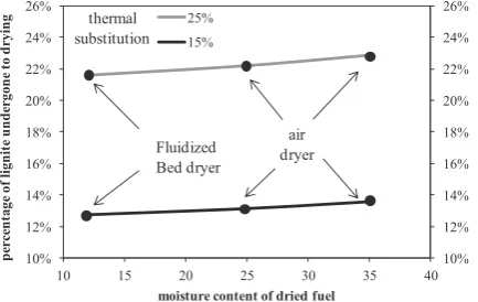
Different configurations are examined for each basic case, depending on the heating medium source and the basic compo-nents used in the drying process. In order to have a common measure of the two different drying concepts, the thermal share of substitution of raw lignite by dry lignite was set as constant and equal to 25%. Since the air drying process usually operates in lower temperatures (50e80C), the drying capacity of the process (i.e. massflow of moisture evaporated per fuel thermal input) is lower compared with the fluidized bed drying process utilizing low pressure steam bleed (drying temperature 110e130C). This means that the fuel input of the air drying system shall be about 10e15% higher than the steam drying system (seeFig. 1), in order to reach the same pre-dried lignite thermal share. Nevertheless as shown in
Fig. 1, the percentage of the coal massflow to be dried compared with the total massflow input, when keeping constant pre-dried lignite thermal share is similar for both drying technologies due to large amounts of raw coal, which are still required in the regarding co-firing cases.
2. Methodology
2.1. Drying methods
The description of the drying technologies under investigation is divided in two parts. On the one hand, the description of the drying mechanism and the configuration of each technology are pre-sented. On the other hand, the available options for the adequate heat provision are also analyzed (heat integration with the power plant).
2.1.1. Fluidized bed dryer with steam
The WTA concept of fuel drying in afluidized bed using steam as
fluidizing medium has been described in previous studies[26,27]. The steam for thefluidization is a part of the evaporated moisture that is extracted after cyclone separation. The heat source can either be extracted steam from the steam turbine (Fig. 2a) or evaporated moisture of the fuel, recompressed and recirculated (Fig. 2b).An alternative option for the heat source is also examined in thefluidized bed dryer concept, where the heating medium is water from the feed-water tank of the facility.
2.1.2. Air dryer
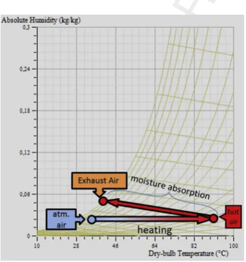
The concept of air drying includes the drying of the fuel through a stream of preheated air. The air is initially preheated by a certain temperature heat source. Furthermore it heats up the fuel up to the evaporation point and absorbs the evaporated moisture, increasing its own relative humidity at the same time. This method has the advantage of allowing the drying process to be performed quickly and safely, avoiding self-ignition issues. The outlet air is saturated in most cases and cooled down, and so it cannot be used further in the process; therefore, after the lignite pre-drying, it is released to the atmosphere, following a fundamentalfiltering.
[image:3.595.321.538.582.719.2]The aforementioned changes in the condition of air during the drying process can be displayed in a psychrometric chart inFig. 3. The quantity of required air and the heat consumption for the drying process has been calculated for different drying tempera-tures through Simprosys v3.0, a software specialized in drying processes[28]. The calculations have been performed for fuel with 25% and 35% moisture content at the air dryer outlet and the results are shown inFig. 4.
Fig. 1.Correlation of mass fraction of dried lignite to the moisture content and the drying method.
K. Atsonios et al. / Applied Thermal Engineering xxx (2013) 1e9
2
1 2 3 4 5 6 7 8 9 10 11 12 13 14 15 16 17 18 19 20 21 22 23 24 25 26 27 28 29 30 31 32 33 34 35 36 37 38 39 40 41 42 43 44 45 46 47 48 49 50 51 52 53 54 55 56 57 58 59 60 61 62 63 64 65
As shown in Fig. 4, the required air flow rate for a certain moisture content in dried fuel decreases at higher inlet tempera-tures. Hence, the power consumptions at the air fan also drop. On the other hand, the heat duties for air heating before the dryer increase up to the temperature of 80C where they reach a local maximum and then they keep increasing in higher temperatures. It should be pointed out that although power requirements are higher at lower temperatures, the exergy losses are lower due to lower temperature differences between solid fuel and the incoming hot air. The determination of the dried fuel moisture content is correlated with both the heat and energy requirements for the drying process. It is observed that for temperatures greater than 140 C both the required heat consumptions and the required amount of air tend to get stabilized.
The heat load for air preheating before it enters the air-drier can be provided by two sources:
2.1.2.1. Heat from extracted water from the feed-water tank. The feedwater tank contains water to be used for the Rankine steam cycle. A vapour stream is used there for deaeration and
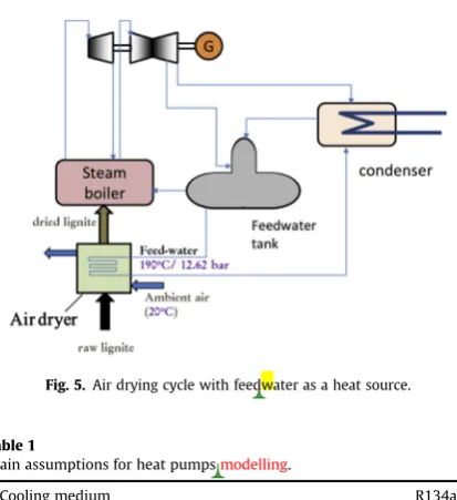
heating of the boiler feedwater, which has also been preheated from the upstream preheaters. Thus, it is in appropriate conditions to be used for heating in the drying process. The stream used from the feed-water tank in the dryer returns back at the condenser and re-enters the cycle. The feedwater that is extracted from the tank is at 190C/12.62 bar. The drying system configuration is presented in Fig. 5. After the air preheating, the feedwater returns to the condenser and mixes with the rest condensates.
2.1.2.2. Heat from heat pump. Heat pump technology is an
inter-esting option for effective heating near at ambient temperatures, like in air-drier case. The heat source for the inlet air temperature elevation comes from the condensation of the cooling medium. The main operating parameters of the heat pump system are summa-rized inTable 1.
The simulations were performed in ASPEN PlusÔin order to calculate the power consumptions and other design and other process parameter of the heat pump in each case, as cooling me-diumflow rate, COP and pressure ratio. The methodology for the cooling medium flow rate is correlated with the drying heating load, while the pressure ratio calculation is based on the meet of temperature approach requirements at the two heat exchangers. Two alternative options are presented for the location of the evaporator that practically imply where the cooling loads are taken from:
2.1.2.2.1. After the air dryer by cooling the out-coming (wet) air. The drying system configuration is exposed inFig. 6.
[image:4.595.102.505.67.201.2]A part of the inlet air sensible heat is provided for the latent heat of evaporation of the moisture, resulting to a lower air temperature at the exit of the dryer. This temperature and the moisture content
Fig. 3.Psychrometric chart with the changes of air conditions during drying.
2500 2750 3000 3250 3500
0 10 20 30 40 50 60
30 80 130 180
specif
ic heat consum
pti
on
(k
Jth/k
g
rem
oved
m
o
ist
ure)
k
g
air/k
g
dried
fuel
air inlet temperature (oC) fuel moisture 35%
fuel moisture 25%
Fig. 4.Effect of air inlet temperature on the required airflow rate and the heat consumption.
[image:4.595.47.290.469.728.2]a
b
Fig. 2.a: Fluidizedbed dryer system, heat medium: extracted steam from the ST or extracted water from the feedwater tank. b: Fluidizedbed dryer system, heat medium: recirculating and recompressed steam.
1 2 3 4 5 6 7 8 9 10 11 12 13 14 15 16 17 18 19 20 21 22 23 24 25 26 27 28 29 30 31 32 33 34 35 36 37 38 39 40 41 42 43 44 45 46 47 48 49 50 51 52 53 54 55 56 57 58 59 60 61 62 63 64 65
[image:4.595.311.564.588.716.2]in the air stream determine the level of evaporation of the cooling medium, affecting theCOPand the pressure ratio of the heat pumps system. The water condensation in the evaporator should be taken into account at the design of the heat exchanger. This concept has the feature that the performance of the heat pump system (COP) is independent of the ambient conditions as the levels of the oper-ating temperatures are determined by the user.
2.1.2.2.2. At the water cooling system before the inlet of the
cooling water to the steam condenser. In this case, the outlet
perature of the cooling water (CW) is higher than the outlet tem-perature of the air at the previous case, decreasing the temtem-perature difference between condensation and evaporation (Thot/Tcold). It is
clear that the performance of the heat pumps is strongly associated with the ambient conditions, since the ambient pressure determine the steam condenser voidage and consequently, the outlet tem-perature of the CW. Nevertheless in the frame of this study, the ambient conditions are assumed stable and same with the refer-ence case (15C, 1.01325 bar, 60% relative humidity) (Fig 7
Q3 ).
2.1.2.3. Heat from steam turbine extraction. This case uses steam
from an intermediate steam turbine extraction to heat the air for the air-drying. The configuration is the same with the case in which water from the feedwater tank is used, with the exception that here the heating medium is steam. The temperature and pressure level of the steam extraction varies, depending on the targeted drying temperature, but for the cases examined in this study, they
generally range between 280 and 380 C and 4.8e11.2 bar, respectively. The layout of the air drying cycle using steam as a heat source can be seen inFig. 8.
2.2. Reference plant description
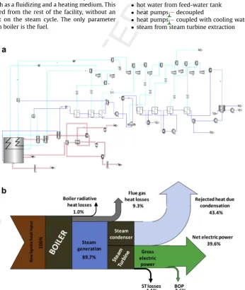
The effect of pre-drying and the optimization of the drying method will be evaluated through thermal cyclemodelling calcu-lations in a lignite-fired power plant. The plant layout used for the investigation is typical for the state-of-the art steam cycle to be applied for low rank coal utilization. The estimated net efficiency rate is 39.6%. The nominal electric power is 586 MWewith one
reheat steam cycle and seven water preheaters with steam extraction from the steam turbine (ST). The superheated steam parameters are 610C/280 bar, while the reheated parameters are 620C/60 bar. The main characteristics of the fuel and the reference plant are summarized below (Tables 2and 3respectively) and a detailed flowsheet diagram of the considered steam cycle as modelled in GatecycleÔ 6.1 is presented in Fig. 9a. The energy balance for the reference case is depicted through the Sankey diagram inFig. 9b.
2.3. Case description
2.3.1. Fluidized bed dryer cases
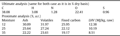
[image:5.595.55.262.58.284.2]In all thefluidized bed dryer cases, dry lignite with 12% moisture is used. The ultimate and proximate analysis of the fuel is given in Table 4.
Fig. 5.Air drying cycle with feedwater as a heat source.
Table 1
Main assumptions for heat pumpsmodelling.
Cooling medium R134a
[image:5.595.304.547.64.206.2]Compressor isentropic efficiency 70% Condenser temperature approach 5C Evaporator temperature approach 3C
Fig. 6.Heat pump integrated with the air dryeredecoupled with the rest power plant.
[image:5.595.48.545.569.731.2]Fig. 7.Heat pump integrated with the air dryerecoupled with the CW system.
Fig. 8.Air drying cycle with steam as a heat source.
K. Atsonios et al. / Applied Thermal Engineering xxx (2013) 1e9
4
1 2 3 4 5 6 7 8 9 10 11 12 13 14 15 16 17 18 19 20 21 22 23 24 25 26 27 28 29 30 31 32 33 34 35 36 37 38 39 40 41 42 43 44 45 46 47 48 49 50 51 52 53 54 55 56 57 58 59 60 61 62 63 64 65
[image:5.595.37.297.622.729.2]Thefluidized bed drying cases examined are the following: 1 Drying using low enthalpy extracted steam
Steam from the LP stage of the Steam turbine is used (29.7 kg/s, 300C, 5.96 bar). The steam delivers its heat in thefluidized bed dryer and the condensate returns in the cycle through the water preheater before the feedwater tank. The evaporated moisture from the fuel can be used as a heating medium for an extra, parallel water preheater, saving steam extractions for heating in the exist-ing preheaters.
2 Drying using vaporized moisture recirculation
In this case, evaporated moisture of the fuel, recompressed and recirculated is used both as afluidizing and a heating medium. This system works decoupled from the rest of the facility, without an interaction and impact on the steam cycle. The only parameter influenced in the steam boiler is the fuel.
3 Drying using feeding water
As previously described, feedwater from the tank (117 kg/s, 190C/12.62 bar) is used in this case as a heating medium in the dryer and returns back at the condenser, re-entering the cycle.
2.3.2. Air drying cases
In the air drying cases, dry lignite is used with i) 35% and ii) 25% moisture content For both of the above cases, the following cases are distinguished, depending on the medium providing heat to the drying air as they were described above:
hot water from feed-water tank heat pumpsedecoupled
heat pumpsecoupled with cooling water steam from steam turbine extraction
[image:6.595.315.557.84.158.2]Fig. 9.a: Flow chart of the examined steam cycle in GateCycleÔin % of the Boiler Heat Input (on anLHV basis). b: Sankey diagram of the Reference lignite power plant.
Table 2
Raw lignite characteristics.
Ultimate analysis (% dry basis)
C H N O S
[image:6.595.130.477.312.723.2]38.08 3.08 1.28 22.41 0.96 Proximate analysis (%, a.r.) LHV(MJ/kg, dry) Moisture Ash Volatiles Fixed carbon 14.41 53.2 16.0 17.0 13.8
Table 3
Reference power plant main characteristics.
Thermal input (MWth) 1481.5
Raw fuelflow rate, kg/s 272.2 Superheated steamflow rate, kg/s 492.7 Reheated steamflow rate, kg/s 396.8 Gross power production, MWe 624.8
Net power production, MWe 586.2
Net electric efficiency, % LHV basis 39.57 Specific CO2emissions, kg CO2/kWhe, net 0.903 1
2 3 4 5 6 7 8 9 10 11 12 13 14 15 16 17 18 19 20 21 22 23 24 25 26 27 28 29 30 31 32 33 34 35 36 37 38 39 40 41 42 43 44 45 46 47 48 49 50 51 52 53 54 55 56 57 58 59 60 61 62 63 64 65
Finally, the influence of drying air temperature is also investi-gated as a parameter. In the cases examined, three representative temperatures were selected, 60C, 110C, 140C.
For the FD fan it is assumed it has a 70% isentropic efficiency and a 40 mbar pressure increase. The ultimate and proximate analysis of the fuel for these cases is given inTable 4.
The characteristics of the test cases that are under investigation are summarized inTable 5. The thermal substitution for all cases is assumed 25%.
3. Results and discussion
The results of the performed investigation are presented in the following analysis. What is mainly focused is the attitude of the drying technologies under investigation at the total net efficiency from a thermodynamic and economic point of view. Furthermore the impact of various parameters like dried fuel moisture content and the selection of the heat source on the performance of the power system are also examined.
3.1. Fluidized bed dryer cases
The basic results of the cases with thefluidizedbeddryer are summarized inTable 6.
A comparison between the net electric efficiency of the plant for each case can be seen inFig. 10. The results reveal that thefluidized bed drying technology concept is an interesting option for
retro-fitting drying as the efficiency of the plant increases more than 1.3%. Case 2 representing thefluidizedbed dryer with steam recircula-tion has the greatest efficiency. In other words, it is more preferable to use dedicated compressors for steam compression than to extract steam or feedwater from the steam cycle. The waterflow rate at case 3 is six times greater than the other two cases. This fact leads to larger heat exchanger inside the dryer occupying more space inside the bed, making thefluidization more difficult.
3.2. Air dryer cases
The basic results of the cases with the air dryer are summarized inTable 7.
According toTable 7, in this initial assessment the air dryer concept has in general terms a small beneficial impact on plant performance for the air inlet temperature of 60C. This is mainly attributed to the power consumption at the air drying fans and the energy penalty for the air heating; for the cases 4 and 7, the gross power output drops, due to the extraction of large quantity of water (around 15% of the total water) for air heating. Although the steam production is not affected the gross output decreases because more steam is extracted from the turbines for the feedwater LP pre-heating. As it is seen, extracted feedwater from the tank is the best option as a heat provider to the air, for certain dried fuel moisture content. For the cases employing heat pumps (5, 6, 8, 9), extra power consumptions for heat pump operation (i.e. cooling medium compression) further deteriorates the efficiency of the plant. It is proved that the best option for the evaporation of the cooling medium is by coupling with the cooling water after the steam condenser, owed to the lower difference between the operating temperatures of the heat pumps that affect the pressure ratio at the cycle.
For air heating temperatures >60 C the application of heat pumps does not operate efficiently, as the pressure ratio increases and the COP drops considerably at unacceptable levels.
[image:7.595.35.284.84.159.2]On the other hand, the efficiency for air heating temperatures >60C (110C and 140C) is compared in the cases of feedwater and steam extraction as a heating medium. It occurs that a higher air heating temperature also leads to an efficiency improvement in these cases. The optimum case is the case of using extracted feed-water to heat air at 110C (case 10) which is also the optimum case Table 6
Main results of thefluidizedbed dryer cases.
Cases 1 2 3
Dried fuel moisture (%) 12% 12% 12% Total fuel (kg/s) 260.37 260.37 260.37 Dried fuel (kg/s) 29.91 29.91 29.91 Steam generation (kg/s) 497.8 497.76 497.79 Heat for drying (MWth) 77.65 77.65 77.65
Dryer energy duty (MWe) 2.11 5.75 2.11
Fluidization medium low rate (kg/s) 70.7 70.7 70.7 Heating mediumflow rate (kg/s) 29.7 21.9 117.1 Gross power output (MWe) 622.05 634.02 619.57
Net power output (MWe) 582.07 590.24 579.49
Net electrical efficiency (%) 41.07% 41.65% 40.89%
Deff. (%) þ1.50% þ2.07% þ1.32%
Fig. 10.Efficiency for thefluidizedbed dryer cases compared to Reference case.
Table 4
Dried lignite characteristics for both moisture contents.
Ultimate analysis (same for both case as it is in % dry basis)
C H N O S
38.08 3.08 1.28 22.41 0.96 Proximate analysis (%, a.r.)
Moisture Ash Volatiles Fixed carbon LHV(MJ/kg, raw) 12 30.09 31.97 25.95 12.38
[image:7.595.299.552.85.243.2]25 25.64 27.24 22.12 10.19 35 22.22 23.61 19.17 8.51
Table 5
Test cases.
a/a Drying technology
Drying temperature
Dried fuel moisture
Heat source
1 Fluidized bed dryer
110C 12% Steam extraction from ST
2 Steam circulation
3 Hot water from feed-water tank 4 Air dryer 60C 35% Hot water from feed-water tank
5 Heat pumps - decoupled
6 Heat pumps - coupled with cooling water
7 25% Hot water from feed-water tank
8 Heat pumps - decoupled
9 Heat pumps - coupled with cooling water
10 110C 25% Hot water from feed-water tank
11 Steam from ST
12 140C 25% Hot water from feed-water tank
13 Steam from ST
K. Atsonios et al. / Applied Thermal Engineering xxx (2013) 1e9
6
1 2 3 4 5 6 7 8 9 10 11 12 13 14 15 16 17 18 19 20 21 22 23 24 25 26 27 28 29 30 31 32 33 34 35 36 37 38 39 40 41 42 43 44 45 46 47 48 49 50 51 52 53 54 55 56 57 58 59 60 61 62 63 64 65
[image:7.595.42.552.569.745.2]for all the air-drying cases. A further increase of air heating tem-perature (case 12) limits the improvement of the efficiency, as the gross power output is decreased significantly due to the use of a large quantity of feedwater for air heating (around 25% of the total water), and the corresponding use of a large steam extraction quantity for the feedwater LP preheating. Steam extraction used for air heating (cases 11 & 13) presents the reverse behaviour, as in a higher temperature, the steam production is not affected but less steam extraction is required as the steam used is of a higher temperature.
An efficiency comparison of the air drying cases (4e13) to the reference case is shown inFig. 11.
3.3. Mass and energy balance
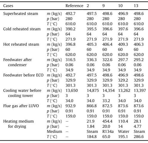
Selected cases representing the optimum scenarios for each pre-drying concept are presented in more detail with respect to the thermodynamic characteristics, heat and massflows. Massflows and other thermodynamic characteristics such as pressure and temperature are presented inTable 8and heat streams are pre-sented in the Sankey diagrams ofFig. 12aed. In addition to the reference case shown inFig. 9b, the selected cases are:
case 2, which is the optimum fluidized bed dryer case with steam recirculation,
case 9, which is the optimum heat pumps case (coupled with cooling water, at 60C drying temperature and 25% dried fuel moisture content),
case 10, which is the optimum air dryer case with feedwater as heating medium (110C drying temperature) and
case 13, which is the optimum air dryer case with steam as heating medium (140C drying temperature).
[image:8.595.110.556.82.437.2]Several conclusions are drawn fromTable 8. When the thermal share coming from pre-dried lignite is 25%, then the steam pro-duction is increased by 1% compared to the reference case. This is owed to the greater amount of available heat for steam generation, since the adiabatic temperature is greater. The steam that un-dergoes to phase change in the main condenser is lower in cases 10 and 13 than the other pre-drying cases. In case 10, more steam is extracted from the Low Pressure Steam Turbine for condensate water preheating, since part of the condensate is led for air pre-heating at the Air Dryer unit. In case 13, 28.1 kg/s steam is condensed in the air dryer preheater and not in the main condenser. Table 7
Main results of the air dryer cases. Q4
Cases 4 5 6 7 8 9 10 11 12 13
Dried fuel moisture (%) 35% 35% 35% 25% 25% 25% 25% 25% 25% 25% Total fuel (kg/s) 264.59 264.59 264.59 262.36 262.36 262.36 262.36 262.36 262.36 262.36 Dried fuel (kg/s) 43.53 43.53 43.53 36.33 36.33 36.33 36.33 36.33 36.33 36.33 Steam generation (kg/s) 497.0 497.5 497.5 496.88 498.6 498.6 496.91 498.56 498.5 498.7 Air for drying (kg/s) 1274 1274 1274 1636 1636 1636 782.86 782.86 600.5 600.5 Drying temperature (C) 60 60 60 60 60 60 110 110 140 140 Feedwater/steam for air heating (kg/s) 80.8 e e 103.7 e e 110.37 29.86 133.9 28.1 Heat for drying (MWth) 51.58 51.58 51.58 67.45 67.45 67.45 71.82 71.82 72.9 72.9
Dryer energy duty (MWe) 5.15 5.15 5.15 6.73 6.73 6.73 3.22 3.22 2.47 2.47
Heat pumps energy duty (MWe) e 18.5 10.1 e 22.0 13.3 e e e e
COP of heat pump e 3.64 5.09 e 3.07 3.89 e e e e
Thot/Tcold(C) e 65.0/10.2 65.0/30.4 e 65.0/9.8 65.0/30.2 e e e e pcond/pevap(bar) e 20.0/4.0 20.0/7.5 e 20.0/4.0 20.0/7.5 e e e e
Cooling mediumflow rate (kg/s) e 345.5 347.8 e 431.6 454.4 e e e e
Gross power output (MWe) 621.652 628.78 628.78 619.94 630.35 630.35 619.11 611.17 611.53 612.05
Net power output (MWe) 578.4 566.8 575.22 575.16 563.52 572.22 577.85 570.12 571.13 571.73 Net electrical efficiency (%) 40.16% 39.36% 39.94% 40.28% 39.46% 40.07% 40.46% 39.92% 39.99% 40.04% Deff. (%) þ0.6% 0.2% þ0.4% þ0.7% 0.1% þ0.5% þ0.89 þ0.35 þ0.42% þ0.47%
[image:8.595.312.560.507.746.2]Fig. 11.Efficiency for the air drying cases (4e13) compared to Reference case.
Table 8
Thermodynamic characteristics of water/steam,flue gas and heating mediumflows for selected cases.
Cases Reference 2 9 10 13
Superheated steam m(kg/s) 492.7 497.5 498.6 496.9 498.6
p(bar) 280 280 280 280 280
T(C) 610.0 610.0 610.0 610.0 610.0
Cold reheated steam m(kg/s) 390.2 395.5 396.6 397.6 396.6
p(bar) 64 64 64 64 64
T(C) 271.9 271.9 271.9 271.9 271.9 Hot reheated steam m(kg/s) 396.8 405.3 406.4 409.3 406.3
p(bar) 60 60 60 60 60
T(C) 620.0 620.0 620.0 620.0 620.0
Feedwater after condenser
m(kg/s) 316.5 336.3 322.6 297.7 295.2
p(bar) 0.06 0.06 0.06 0.06 0.06
T(C) 34.9 34.9 34.9 34.9 34.9
Feedwater before ECO m(kg/s) 492.7 497.5 498.6 496.9 498.6
p(bar) 329.9 329.9 329.9 329.2 329.9
T(C) 301.3 301.3 301.3 301.3 301.3
Cooling water before cooling tower
m(kg/s) 13,650 14,875 14,354 13,262 13,397
p(bar) 3 3 3 3 3
T(C) 34.0 34.0 33.2 34.0 34.0
Flue gas after LUVO m(kg/s) 932.9 866.8 872.5 873.6 873.6
p(bar) 0.91 0.91 0.91 0.91 0.91
T(C) 159.0 159.0 159.0 159.0 159.0
Heating medium for drying
m(kg/s) e 21.9 454.4 110.4 28.1
p(bar) e 1.84 20.0 14 4.77 Medium e Steam R134a Water Steam
T(C) e 184.8 65.0 195.1 286.6 1
2 3 4 5 6 7 8 9 10 11 12 13 14 15 16 17 18 19 20 21 22 23 24 25 26 27 28 29 30 31 32 33 34 35 36 37 38 39 40 41 42 43 44 45 46 47 48 49 50 51 52 53 54 55 56 57 58 59 60 61 62 63 64 65
a
b
c
[image:9.595.127.457.62.712.2]d
Fig. 12.a: Sankey diagram of Case 2 (FB Dryer with steam recirculation) in % of the Boiler Heat Input (on anLHV basis). b: Sankey diagram of Case 9 (Air Dryer with heat pumps) in % of the Boiler Heat Input (on anLHV basis). c: Sankey diagram of Case 10 (Air Dryer with hot water extraction) in % of the Boiler Heat Input (on anLHV basis). d: Sankey diagram of Case 13 (Air Dryer with steam extraction) in % of the Boiler Heat Input (on anLHV basis).
K. Atsonios et al. / Applied Thermal Engineering xxx (2013) 1e9
8
1 2 3 4 5 6 7 8 9 10 11 12 13 14 15 16 17 18 19 20 21 22 23 24 25 26 27 28 29 30 31 32 33 34 35 36 37 38 39 40 41 42 43 44 45 46 47 48 49 50 51 52 53 54 55 56 57 58 59 60 61 62 63 64 65
Consequently, the required cooling waterflow rate is decreased in these two cases. In case 9, the cooling water temperature before the cooling tower is 0.8C less than the other cases, due to cooling from heat pump medium evaporation. This fact has an effect on the reduction of the cooling load that is should be removed in the cooling tower. Afinal comment on the basic streams characteristics is about the heating mediumflow rates for pre-drying. In case 9 (heat pumps), the R134aflow rate is much greater compared to the other cases, resulting to higher equipment cost.
Fig. 12depicts the Sankey diagrams for the selected pre-drying concepts. It is more than evident the fuel upgrading through pre-drying as illustrated by the reduced required heat and fuel input in the boiler.
4. Conclusions
Comparing the two drying technologies, it is concluded that the fluidizedbed dryer is a more efficient option for retrofitting existing power plants. Calculations reveal that steam recirculation and condensation in the dryer is the best option to provide adequate heat for drying. Air dryer technology at low temperatures is less beneficial than thefluidized bed dryer with steam recirculation as far as total plant performance is concerned, due to the energy penalty in the fans and heat exchangers for heating and transport of air. The air drying concept is not proven yet in a large plant scale; hence additional development work is needed towards deter-mining an optimized configuration, in order to increase its competitiveness. The additional analysis work to be carried out towards cycle optimization shall include, the utilization of the hot water extraction from the feed-water tank as a heat source for air drying. Attention should also be paid to the investigations for the impact of variations in ambient conditions, i.e. change in temper-ature and relative humidity on air dryer performance.
References
[1] M. Eyll Vetter, Coal, a Sustainable Energy Source with Long Term Reliability, European Coal Days, Brussels, 2010.
[2] N. Tanaka, The Role of Clean Coal in the Energy Future, CCT, Zaragoza, Spain, May 2011.
[3] J. Lipponen, Carbon Capture and Storage Potential Challenges in the Global Context, CCT, Zaragoza, Spain, May 2011.
[4] P. Markewitz, R. Bongartz, Energy Technologies 2050: R&D Priority Setting for Coal Fired Power Plants in Germany, CCT, Zaragoza, Spain, May 2011. [5] G.-N. Stamatelopoulos, WTA offers big efficiency gains, Modern Power Syst.
(December 2007) 17e21.
[6] C. Zimmer, R. Leithner, Wirkungsgradverbesserung eines konventionellen Kraftwerks durch Braunkohletrocknung mit Abgas, Brennstoff-Wärme-Kraft BWK 47 (3) (1995) 78e81.
[7] L. Brandau, P. Fritz, R. Gollnick, R. Leithner, J. Wang, J. Reher, Wirkungs-gradverbesserung und Leistungssteigerung von Braunkohlekraftwerken, in: 23 Kraftwerkstechnisches Kolloquium, Dresden, 1991.
[8] T. Rupprecht, Chr Fielenbach, Efficiency and FlexibilityeTechno-economical Challenges for Pre-Dried Lignite Fired Power Plants, Powergen, June 2011, pp. 7e9.
[9] T. Buddenberg, K. Burmann, T. Furth, A. Leisse, R. Jeschke, G. Papenheim, U. Lohmann, Indirectfiring system to increaseflexibility of existing steam co-generation plants, VGB Power Tech. (11/2012).
[10] T. Harkin, A. Hoadley, B. Hooper, Process integration analysis of a brown
coal-fired power station with CO2capture and storage and lignite drying, Energy
Procedia 1 (2009) 3817e3825.
[11] M. Liszka, A. Zie˛bik, Coal-fired oxy-fuel power uniteprocess and system analysis, Energy 35 (2) (2010) 943e951.
[12] E. Kakaras, A. Koumanakos, A. Doukelis, D. Giannakopoulos, I. Vorrias, Oxyfuel boiler design in a lignite-fired power plant, Fuel 86 (2007) 2144e2150. [13] E. Kakaras, A. Doukelis, D. Giannakopoulos, A. Koumanakos, Economic
im-plications of oxyfuel application in a lignitefired power plant, Fuel 86 (14) (2007) 2151e2158.
[14] H.J. Klutz, C. Moser, D. Block, WTA-Feintrocknung, Baustein fuer die Braun-kohlekraftwerke der Zukunft, VGB Power Tech. (11/2006).
[15] F. Schwendig, H.J. Klutz, J. Ewers, Das Trockenbraunkohle befeuerte Kraftwerk, VGB Power Tech. (12/2006).
[16] EUeRFCS Final Report Project“Drycoal”(RFCP-CT-2004-00002).
[17] E. Kakaras, P. Ahladas, S. Syrmopoulos, Computer simulation studies for the integration of an external dryer into a Greek lignitefired power Plant, Fuel 81 (2002) 583e593.
[18] C. Bergins, K. Strauss, Advanced processes for low rank coal drying and dewatering in high efficient power plants, Int. J. Glob. Energy Issues 28 (2/3) (2007) 241e263.
[19] H. Pawlac-Kruczek, J. Lichota, Z. Plutecki, Efficiency of brown coal dryer depending on drying method, in: 36th International Technical Conference on Clean Coal & Fuel Systems, 5e9 June 2011, pp. 1023e1031. Florida USA.
[20] T. Porsche, L. Thannhaeuser, O. Hoehne, J.S. Martin, Erste Testergebnisse von der Versuchsanlage zur Druckaufgeladenen Dampfwirbelschicht-Trocknung (DDWT) von Braunkohlen, 2009, ISBN 978-3-18-092056-6, 24. German Flameday.
[21] M. Ness, C. Bullinger, Pre-Drying the Lignite in GRE’s Coal Creek Station, source:www.netl.doe.gov.
[22] Great River Energy, Dryfining fact Sheet, available online.
[23] M. Agraniotis, P. Grammelis, C. Papapavlou, E. Kakaras, Experimental inves-tigation on the combustion behaviour of pre-dried Greek lignite, Fuel Process. Technol. 90 (2009) 1071e1079.
[24] M. Agraniotis, Substitution of Coal by Alternative and Supporting Fuels in Pulverised Fuel Boilers towards Reduction of CO2 Emissions, PhD Thesis,
January 2011 (available online).
[25] M. Agraniotis, S. Karellas, I. Violidakis, A. Doukelis, P. Grammelis, E. Kakaras, Investigation of the pre-drying of lignite in an existing Greek power plant, Therm. Sci. 16 (1) (2012) 283e296.
[26] M. Agraniotis, A. Koumanakos, A. Doukelis, S. Karellas, E. Kakaras, Investiga-tion of technical and economic aspects of pre-dried lignite utilisaInvestiga-tion in a modern lignite power plant towards zero CO2emissions, Energy 45 (1) (2012)
134e141.
[27] I. Vorrias, K. Atsonios, A. Nikolopoulos, N. Nikolopoulos, P. Grammelis, E. Kakaras, Calcium looping for CO2capture from a lignitefired power plant,
Fuel 113 (2013) 826e836. [28] http://www.simprotek.com/.
1 2 3 4 5 6 7 8 9 10 11 12 13 14 15 16 17 18 19 20 21 22 23 24 25 26 27 28 29 30 31 32 33 34 35 36 37 38 39 40 41 42 43 44 45 46 47 48