Improving seasoned hardwood timber quality
with particular reference to collapse
by
Trevor Craig Innes B.E. (Hons.)
Submitted in fulfilment of the requirements for the degree of Doctor of Philosophy
in the Faculty of Engineering UNIVERSITY OF TASMANIA
Australia
I hereby declare that, except as stated herein, this thesis contains no material which has been accepted for the award of any other degree or diploma in any university and that, to the best of my knowledge and belief, this thesis contains no copy or paraphrase of material previously published or written by any other person, except where due reference is made in the text of the thesis.
T.C. limes
This thesis may be made available for loan and limited copying in accordance with the Copyright Act 1968.
J
Abstract
This thesis principally concentrates on the prevention of degrade due to collapse during the controlled kiln drying of timber. Collapse is an abnormal shrinkage which occurs in wood during drying to fibre saturation point (FSP). Formation of internal checking is often associated with it. Collapse is particularly common in native Australian eucalypt timbers.
Specific work was also performed on the drying of karri (Eucalyptus diversicolor
F.Muell) and brushbox (Tristania conferta R.Br.) as part of the commercialisation process of the Clever Kiln Controller® (CKC). The CKC is a personal computer based kiln control package which uses sensed acoustic emissions (AE) and on-line modelling of drying to optimise the seasoning process.
Collapse shrinkage occurs as a result of the physical flattening of water filled fibre cells due to the action of internal tension. The work on collapse presented in this thesis begins with stress-strain modelling of a single fibre under such conditions. This model predicted that collapse of fibres is precipitated at the inner fibre wall, and that fibre collapse is strongly dependant on temperature.
Following the predictions of the single fibre model and observations of drying trials, the concept of a "collapse threshold temperature" was introduced. If wood at moisture content (MC) above FSP is dried at temperatures above the collapse threshold temperature, then it will collapse. If it is dried at temperatures below the collapse threshold temperature, then it will not collapse. This concept was first tested on a 20m3 kiln load of Eucalyptus regnans F.Muell. The timber was successfully dried to 40% MC free of collapse.
An existing model of the timber seasoning process was modified to model wood as a heterogeneous material. This model showed that if the dry bulb temperature exceeded the collapse threshold temperature during drying to FSP (that is, if collapse shrinkage occurred), then checking was very difficult to avoid, even if the humidity of the modelled schedule was very high, and the drying thus very slow.
strain relaxation by creep or mechano-sorptive deformation. The most likely cause for the variation of collapse threshold temperature during drying was shown to be the effect of bulk stress in the board due to drying.
Drying trials controlled by the CKC were conducted on batches of karri and brushbox. The drying trials yielded information on the two species which allowed accurate modelling of their behaviour. The work on karri revealed a stress raiser effect from opened vessels lying along the surfaces of boards; modelling of the effect produced results consistent with those from drying trials and acoustic emission monitoring.
Acknowledgments
The author gratefully acknowledges the assistance and support of the following individuals and companies throughout the project:
Emeritus Professor Arch Oliver, supervisor, for his enthusiastic guidance, support and many discussions.
Associate Professor Peter Doe, supervisor, for his excellent advice and organisational assistance.
James Booker and Jason Woolley, fellow postgraduate students, for their helpful discussions and good company.
Helen Tonks for assistance with proof reading.
Australasian Furnishing Research and Development Institute Ltd. for financial assistance, and Michael Lee in particular for his valuable advice.
My family and friends for their encouragement and support. Special thanks to Kathy for helping me to maintain my perspective.
Additional publications
The following papers were either published or in press at the time of submission of this thesis:
1. limes, T.C. 1995. Stress model of a wood fibre in relation to collapse. Wood Sci. Tech. 29(5): 363-376.
2. limes, T.C. 1995. Collapse free pre-drying of Eucalyptus regnans F.Muell. Holz als Roh- und Werkstoff 53(6): 403-406.
3. limes, T.C. 1996. Collapse during seasoning of eucalypt timbers. Paper presented at 5th IUFRO International Wood Drying Conference, Quebec City, Canada August 13-17 1996.
4. limes, T.C. 1996. Collapse and internal checking in the latewood of
Eucalyptus regnans F.Muell. Wood Sci. Tech. 30(6): 373-383.
5. limes, T.C. 1996. Pre-drying of collapse prone wood free of surface and internal checking. Holz als Roh- und Werkstoff 54(3): 195-199.
6. limes, T.C. 1997. 'Vessels as surface stress raisers during drying of Eucalyptus diversicolor F.Muell. Wood Sci. Tech. in press.
Contents
Abstract
Acknowledgments
Additional publications vi
Chapter 1. Introduction and literature review 1 Chapter 2 Stress-strain modelling of a fibre cell subjected to 25
internal tension
Chapter 3. The collapse threshold temperature 52 Chapter 4. Modelling of wood as a heterogeneous material 63 Chapter 5. Optimisation of dry bulb temperature during drying to 100
FSP
Chapter 6. The Clever Kiln Controller® 117
Chapter 7. Drying of Karri (Eucalyptus diversicolor F.Muell.) 125
• Chapter 8. Conclusions 159
References 162
Appendix A. Notation
Appendix B. Drying of Brushbox (Tristania conferta R.Br.) Appendix C. Analytical model of a round hole in an orthotropic
infinite plate
Chapter 1. Introduction and literature review
The emphasis of the hardwood sawmilling industry in Australia is slowly shifting away from the traditional base of structural grade timber towards value added products. Sawn timber seasoned with very little or no degrade, suitable for furniture manufacture, is such a product. To this end, timber seasoning research at the University of Tasmania has been directed at the production of sawn native hardwood timber free of seasoning induced degrade. Prior to the work detailed in this thesis, the research here has focused on prevention of surface checking through the use of mathematical modelling of the seasoning process and, more recently, through on-line monitoring of acoustic emission (AE). These two processes were combined in the Clever Kiln Controller® (CKC), (Booker, 1994a; Doe et al, 1996), a personal computer based kiln control package.
This thesis covers two broad areas of research into the controlled kiln drying of eucalypt timber. The first area, and the one which makes up the bulk of the thesis, is research into the problem of collapse during drying of wood to fibre saturation point. The second area is specific work on the drying of two species of timber, karri (E. diversicolor) and brushbox (Tristania conferta). This work was performed as part of the development of the CKC. The controller has previously been tested on E. regnans, E. delegatensis R.T. Bak. and E. obliqua L'Herit. and is nearing commercial application.
The work presented here consists of mathematical modelling in conjunction with physical observation and measurement to gain further insight into the processes involved in seasoning. Several extensions to an existing timber drying simulation model (KilnSched, see Section 4.1) were developed, and have shed light on some problems in drying.
1.1 The phenomenon of collapse
Collapse has been defined as an abnormal shrinkage of wood. It appears to have been first explained by Tiemann (1915). Collapse shrinkage occurs as a result of physical collapse of fibre cells within the wood. There is still debate in the literature about the actual mechanism and causes of collapse.
As wood dries, it undergoes a volumetric shrinkage. This shrinkage can be separated into two distinct components. The first component is normal shrinkage, which always occurs. The second is collapse shrinkage, which does not always occur.
Water within timber is generally accepted to exist in one of two states. Bound water is chemically bound to the wood cell wall material. Free water exists within the lumens of the wood cells, and is not so bound. The fibre saturation point (FSP) is defined as that moisture content at which all of the free water has been removed, but none of the bound water (Tiemann, 1906 as cited in Siau, 1984). Sharp changes in the behaviour of many wood properties are observed to occur at FSP. Although this model of the wood-water relationship is a simplification of the real situation, it is a useful concept for wood drying research.
Normal shrinkage occurs as a result of removal of moisture from the cell wall material of timber. Thus, normal shrinkage is associated with bound water removal, and will not take place in this simplified model until the moisture content of the timber has been reduced below FSP. In practice, a small amount of normal shrinkage does occur above FSP, because the levels of bonding of water to the cell wall material are complex, and it appears that bound water can be removed from some parts of the wood before all free water has been removed.
1.2 Tiemann's liquid tension theory
It is widely accepted in the literature that the driving force behind collapse shrinkage is hydrostatic tension forces within the fibre lumens. This theory, proposed by Tiemann (1915), is based on the fact that wherever a curved meniscus is formed at a liquid-gas interface, the pressure in the liquid behind the meniscus will be reduced. Correspondingly, there will exist a three dimensional tension stress field at all points on the curved surface of the meniscus. This is the basis for the formation of a droplet of liquid in a gas. The basis for the application of this theory to the problem of collapse is that, as water evaporates out of the pits of fibres, a meniscus forms at the pit. If the radius of the pit (and thus of the meniscus) is sufficiently small, the water inside the cell lumen develops negative pressure. The magnitude of this pressure depends on the principal radii of the meniscus (and hence on the size of the pits).
A liquid held in a capillary behind a meniscus will be at a state of negative pressure P relative to the pressure of the gas with which it is in contact given by
1 1
P = o- —+— (1.2.1)
r2
P= total liquid tension where a = surface tension
ri,r2 = principal radii of meniscus
A correction is necessary for the vapour pressure over the curved meniscus ln(p, – – 2crM
rDRT (1.2.2)
where:
pi = vapour pressure over the curved surface p= vapour pressure over plane surface M= molecular mass of liquid
D= density of liquid R= gas constant
T = absolute temperature a = surface tension r = radius of meniscus
water out of the cell lumens is dominated by molecular diffusion, hence the finding by Schaffner and Doe (1981) that water movement through Tasmanian Oak could be adequately described by Fick's law. There is no certainty that surface tension relationships which describe macro liquid-gas interfaces apply on a molecular scale.
1.3 Classical boiling theory
It is well known in the theory of boiling that a certain minimum size of vapour bubble can grow against surface tension forces. Surface tension forces as described above act in opposition to the internal pressure of a vapour bubble. That is, the pressure inside a vapour bubble must be sufficiently greater than the pressure outside the bubble to overcome the tension field at the interface. Since surface tension forces increase with decreasing bubble radius, there will exist a critical bubble radius at which the system will be metastable. If a vapour bubble forms at a smaller radius than this critical value, it will collapse, given a constant pressure differential across the liquid-vapour interface.
The critical bubble radius as predicted by classical thermodynamics is given by 2o-
rk =- (1.3.1)
rk = critical bubble radius
where 4p= isothermal pressure difference to the saturation line a= surface tension
The activation energy necessary for formation of this bubble may be given by 16go-3
3(Pk P,)
from theory developed by Volmer (1939) as quoted by Gerum et al (1977).
Ak = activation energy
where pk = pressure inside the bubble (.=L• saturation pressure at temperature T) p,= pressure of the liquid phase
The same source quotes a formula for the probability of this activation energy becoming available
16ra3 J = ex(_ --1(17,) 11 (3 exp —
3kT(pk — pi)2 (1.3.3)
Pwater rk (un) 0.337 Pa 72.8 -17.7 kPa 7.28 -97.7 kPa 1.46 -1 MPa 0.146 -10 MPa 0.015 Table 1.3.1 Critical radius where
J= frequency of bubble formation
Zi = number of molecules per unit volume A= latent heat of vaporisation per molecule k= Boltzmann' s constant
b = (Pk - 13)1 Pk
In = mass per molecule
Close inspection of equations 1.3.1 to 1.3.3 show that they are very sensitive to the variables input. In equation 1.3.3, the two exponential terms are very small, whilst Z1 is very large (of the order of 1028), so that the formulation is practically unworkable, although Kauman (1965) calculated some results based on this and some slightly more refined theory. The applicability of this theory to this problem is questionable as it was originally designed for pure liquids, and does not take into account surface effects. Many later researchers (eg. Gerum et al 1977) have investigated surface and nucleation effects, and this is still an area of active research among physicists.
If we assume that the pressure inside the bubble is equal to the vapour pressure of the water (that is, a saturated atmosphere), then we can get at room temperature from equation 1.3.1, values for critical bubble radius corresponding to particular values of water pressure. These values are shown in Table 1.3.1.
Table 1.3.1 shows that, as the tension in water increases, so the critical bubble size decreases. A bubble less than the critical bubble size will collapse while one larger than the critical size will expand. If a capillary were of a smaller diameter than the critical bubble size, then the corresponding tension could be sustained indefinitely, irrespective of the presence of gases or bubble nucleation points.
1.4 Contraction theory
question - what is collapse? The single fibre stress model presented in Chapter 2 of this thesis predicts that round fibres collapse away from radial symmetry with a relatively small loss of free water, and a correspondingly very small contraction - around 0.4%, certainly not enough to cause checking. The near square tracheids in
Pinus radiata studied by Booker may contract more, but buckling of the cell walls seems likely to occur at a similar order of magnitude of contraction to the round fibres. The tracheids would have to maintain their square shape during contraction to maintain the integrity of the wood. The buckling of square tracheids is a complex problem. Simplifying the structure by modelling it as a series of plates or beams seems unlikely to be successful because of the complex fixity conditions at the corners of the tracheids.
1.5 Shrinkage stress induced collapse
It has been postulated by some researchers (Clarke, 1927; Stamm and Loughborough, 1942) that collapse may be induced by compressive stresses resulting from drying of the wood. The liquid tension theory of collapse depends upon the negative pressure developed in the liquid filled lumen becoming sufficiently great to overcome the compressive strength of the cell wall. If this occurs, then the cell will collapse. Theories based solely on shrinkage stress induced collapse do not include any effect of negative pressure in the fibre lumens.
Keylwerth (1951) states that internal cracking may occur in the later stages of drying, when the core of the wood is subjected to tensile stresses due to tensile set at the board surfaces. However, he does not provide experimental evidence to support this claim.
the magnitude of the tension at the surface. The effect of shrinkage stresses on collapse has been investigated in Section 5.4 of this thesis.
Kauman (1960, 1965a, 1965b) presented a comprehensive theory of collapse incorporating liquid tension and compressive stress induced components. According to his theory, collapse is produced when P from equation 1.2.1 is greater than the stress, Q which acts in the wood at the limit of plastic flow. Thus liquid tension collapse CL is given by:
CL = k L (P — 0(1— exp(7-71) (1.5.1)
1cL is a deformation coefficient where t = time
r = relaxation time of the collapse process
For ,compression stress collapse, Kauman replaces the factor (P-Q) by the compressive stress. The compressive stress he calculated as a linear function of the potential difference in shrinkage between case and core.
Kauman found that in E. regnans t was of the order of 2 hours at 20°C and 0.5 hours at 53°C, so that the factor (1-exp(-t/T)) could be taken as constant. He took the remaining factors as being linearly dependant on wood temperature so that total collapse Ci could be written as:
C' = ao + bon +[a l + b,(1— n)]7',„ + b2 (1— n)S ' 0 = wood temperature
S„ = collapse free shrinkage
where ak , bk depend only on surface tension and wood properties
n depends mainly on end drying
j represent the structural directions of the wood
(1.5.2)
Kauman determined capillary radii from sorption isotherm and mercury porosimetry measurements. He approximated pure liquid tension collapse by drying 2.5cm cubes through exposed end grain. His calculations agreed closely with experimental results on total collapse at temperatures between 20°C and 100°C.
reduces the diameter of the capillary, and thus increases the hydrostatic tension (equation 1.2.1). For initial radii smaller than a critical value, the system is unstable, and the capillary will collapse. They showed that for capillaries of the size of wood fibres, the fibre wall elasticity would have a value around that for soft rubber. The applicability of this theory to the problem of fibre collapse thus seems doubtful.
1.6 Factors which affect collapse during drying
Gottstein and McCombe (1956) reported that 'both field and laboratory experiments have indicated that temperature is a factor of major importance, independent of other drying conditions'. Their experimental work consisted of pre-heating veneers of E. delegatensis and E. obliqua to temperatures between 21°C and 66°C and comparing the resultant shrinkage. They found that wood preheated to higher temperature invariably displayed more collapse than wood preheated to lower temperatures.
Vermaas and Bariska (1994) found that Eucalyptus grandis Hill ex Maid. collapsed approximately 2.5% when dried at 20°C, and 3.2% when dried at 30°C, whereas
Pinus silvestris dried under the same conditions exhibited less than 0.5% collapse. Examination of scanning electron micrographs revealed no collapse in P. silvestris but substantial collapse in E. grandis.
Keylwerth (1951) recommends that "one should only increase the initial low drying temperature when the timber does not contain any more free water". For eucalypt timbers he suggests limiting the dry bulb temperature to a maximum of 40°C until the timber reaches FSP.
Kemp (1959) found that time to collapse for aspen (Populus tremuloides Michx.) increased slightly with increase in temperature or humidity. However, his experiments invariably induced collapse within the first three hours of drying. His experiments were carried out between 60°C and 77°C.
considered that increase in collapse with increase in temperature was due to hydrolysis of the fibre wall. His experiments were carried out between 38°C and 137°C. The hydrolysis process was monitored by measuring the pH of the wood. A significant drop in pH was found at the higher temperatures. This effect does not seem to explain the sensitivity of collapse to changes in temperature of approximately 2°C, particularly at lower temperatures.
Position within the tree, both radially and longitudinally, has been found to affect the amount of collapse shrinkage undergone by wood. Pankevicius (1961) found that collapse in E. regnans varied consistently within a tree, decreasing with increase in height. Chafe (1985, 1986b), Cuevas (1969), and Bisset and Ellwood (1951) found that the amount of collapse shrinkage increased with radial distance from the outside of the tree, reaching a peak at approximately 85% of the distance to the centre, and then decreased into the pith.
Collapse is generally located in discrete earlywood bands, so that the occurrence of collapse may coincide with the occurrence of a particular earlywood band rather than with any particular radial position. The location of this band appears likely to be determined by environmental (growth) conditions during its formation. Thus, in a stand of similar trees from the same area, it is expected that the earlywood bands corresponding to the same year of growth would have a similar propensity to collapse in all trees. This has in fact been observed by Amos (1954), who counted internal checks formed in living Pinus radiata. Lutz (1952) similarly observed internal checks in particular growth rings of living white spruce (Picea glauca Moench) in Alaska. Lutz concluded that the checks formed as a result of high internal tension in the tracheids when absorption of water was prevented by the freezing of the ground. Miller and Simpson (1992) found that collapse-associated internal checking in Pinus radiata was concentrated in the annual rings corresponding to the time just after second thinning. Presumably this corresponded to a time of accelerated growth, leading to lower density. Kemp (1959) reported that collapse in aspen started in the springwood.
Since collapse is clearly related to fibre wall stiffness, and hence thickness, and density of the cell wall material varies within small limits (Stamm, 1929 as cited in Bisset and Ellwood, 1951) many researchers have looked for a relationship between collapse shrinkage and bulk density (Chafe, 1985, 1986a; Hillis, 1978). Collapse is found to decrease with increase in density. Normal shrinkage generally increases slightly with increase in density, as all of the fibre wall material shrinks, and there is more of it in denser material (Bisset and Ellwood 1951).
1.7 Cell wall structure
The wood cell walls are composed of three main structural constituents. These are, the framework, the matrix and encrusting materials. The framework consists of cellulose in the form of microfibrils. The matrix is composed of hemicelluloses and other carbohydrate materials. The encrusting materials are lignin and associated amorphous compounds.
The framework and matrix materials can be enzymatically removed to leave exposed the lignin skeleton. This reveals a microcapillary system within the cell wall. This is the area where bound water exists within the cell wall in the green state. Removal of this bound water allows the microfibrils around these microcapillaries to realign closer together. Thus, removal of bound water causes shrinkage of the cell wall material.
1.7.1 Microfibrils
X-ray diffraction and polarisation microscopy revealed the crystalline nature of cellulose in wood. The strand-like nature of the cellulose chains called fibrils was proven by electron microscopy.
Elementary fibrils are assumed to be the smallest possible diameter cellulose strands. According to Kollmann and Cote (1984), Miihlethaler (1960, 1965) termed fibrils with diameter of approximately 35A elementary fibrils. Such a fibril could consist of about forty cellulose chains.
Elementary fibrils are bundled together to make up microfibrils. These can be typically 100 to 300A wide, according to Kollmann and Cote (1984). In turn, microfibrils aggregate to form macrofibrils. These then join together to form lamellae, which make up the cell wall layers.
Along the elementary fibrils there exist sections where the cellulose chains are so closely oriented that X-ray diffraction produces images just like those for pure crystals. These crystalline regions are termed micelles. Between these, where the cellulose chains of the elementary fibrils do not appear to be as closely aligned, are amorphous zones.
1.7.2 Wall structure
Thus, the simple middle lamella and the primary wall are sometimes collectively known as the compound middle lamella.
The secondary wall usually consists of three distinct layers in normal wood. Reaction wood, wood which has formed to counterbalance a leaning tree, can have a fourth layer (Wardrop and Dadswell 1955). The three secondary cell wall layers in normal wood are labelled the Si, S2 and S3 layers, from the outermost layer in. The secondary wall forms inside, and after, the primary wall.
The S1 layer typically consists of 4 to 6 lamellae of microfibrils oriented at approximately 50° to 70° to the cell axis. The lamellae may be crossed, but there is usually a dominant direction, so that the Si layer is essentially made up of microfibril helices in one direction. Like the primary wall, the 51 layer is thin.
The S2 layer is much thicker than the Si. It usually has between 30 and 150 lamellae (Wardrop 1964a). The predominant microfibril direction is approximately perpendicular to that of the Si, at 100 to 30° to the cell axis and the microfibrils in the central part of the S2 are highly oriented. There exist transition lamellae on the outer and inner surfaces of the S2. These transition lamellae vary in orientation from the S1 to the main S2, and from the main S2 to the S3, on the outside and inside of the S2 layer respectively.
The S3 layer usually has a similar thickness to that of the Si layer. It has loosely arranged microfibrils crossed at approximately 20° to 30° to the fibre axis.
1.7.3 Pit structure
Bryan (1960) reported that collapse in Pacific madrone (Arbutus menziesin Pursh) was most intense in areas of heartwood which were dark red. It seems plausible that the dark red colour was the result of extractives which could occlude the pits, increasing the induced surface tension, leading to the increase in collapse.
1.8 Collapse related to wood microstructure
Collapse shrinkage is Clearly related to the stiffness of the fibre walls subjected to the collapse inducing internal tension. This stiffness of the fibres is difficult to measure itself, but can be inferred from measurements on wood samples.
Bisset and Ellwood (1951) demonstrated that greatest collapse occurred within the earlywood in E. delegatensis. The diameter of the earlywood fibres was approximately 20 pm, and diameter of latewood fibres was approximately 12 pm. Wall thicknesses were approximately 3 pm and 5 pm respectively. Hasan (1994) measured earlywood fibre widths of approximately 15.0 pm, and wall thickness of approximately 2.3 pm for regrowth Eucalyptus globulus Labill., while the corresponding values for the latewood were 12.4 pm and 3.8 pm.
Another important parameter in determining fibre wall resistance to collapse is microfibril angle in the Si, S2 and S3 layers within the fibre secondary wall. Panshin and de Zeeuw (1980) report that the microfibrillar orientation in the Si layer is close to 90° on the outside, with a transition to between 500 and 70° on the inside. The S2 layer microfibrils lie parallel between 10° and 30° from the longitudinal direction, while the S3 layer has 60° to 90° microfibrils. Layer thicknesses are 0.1 to 0.2 gm for the Si and slightly less for the S3 with the bulk of the wall made up of the S2 layer.
in beechwood (Fagus sylvatica L.) were predominantly approximately 8 nm in diameter.
Hattori et al (1981) induced collapse in cells of Shorea almon Foxw. by immersing specimens in solutions of polyethylene glycol (PEG). The PEG induced osmotic pressure across the cell walls, which were assumed to act as semi-permeable membranes. The liquid tension in the cell was assumed to be equal to the osmotic pressure induced by the PEG. They found that the ray cell walls were impermeable to PEG of average molecular weight 20000, but permeable to PEG 8100 and PEG 2900. Palin and Petty (1981) quote 3000 as being the lower limiting molecular weight for cell wall impermeability. One would expect this figure to be highly species dependant, as pit size varies significantly from species to species.
1.9 Pre-treatments to reduce collapse
There are two different philosophies for reducing collapse by pre-treatment. The first is to increase the diffusivity of the wood by treatments which open up occluded pits, so that the liquid tension induced is lower. The second is to alter the liquid properties, usually to reduce the surface tension, or to provide nuclei for bubble formation.
Chafe (1993) found that pre-boiling E. regnans resulted in greater shrinkage before reconditioning in the heartwood, but less in the sapwood. Chafe (1990) reported that brief presteaming increased total volumetric shrinkage and collapse shrinkage after drying. Campbell (1960) reported that presteaming for less than six hours increased drying rate without increasing degrade, while presteaming for longer than six hours increased both recoverable and irrecoverable collapse.
Choong et al (1973) reported that collapse in E. delegatensis may be completely eliminated by freeze-drying. It appears that the liquid surface tension may be completely eliminated by sublimation of the water, thus avoiding collapse.
Bariska (1975) found that wood which had been soaked in anhydrous ammonia shrank much more after drying than wood which had not been soaked in ammonia. He reports that "In many respects, this excessive shrinkage resembles the collapse of wood". Interestingly, the surface tension of ammonia is approximately 0.02 at room temperature, about a third that of water (Weast, 1981). It appears likely that ammonia acts as a chemical plasticiser of the wood. Pankevicius (1960) reports unsuccessful attempts to induce bubble formation by impregnation with carbon dioxide gas at pressures of 25 MPa.
Ellwood et al (1963a, 1963b, 1963c) successfully prevented collapse and internal checking by replacing the water in wood with several organic solvents. They attributed this success to three effects; reduction of liquid tension by decrease in liquid surface tension, possible reduction of core compression stresses by modification of liquid (and hence shrinkage) gradients, and greater cell wall stiffness as a result of the swelling effect of the organic liquids. They also found that solvents which were significantly basic or acidic caused an increase of collapse by wood deterioration. Collapse in such wood was generally unrecoverable. They attributed some of the reduction in collapse to decreased adhesion between the solvents and the wood cell surfaces relative to that between water and the wood cell surfaces
1.10 Tension in water and cavitation
It has been known since the mid 1800's that liquids can be subjected to tension forces, that is, absolute pressures less than zero (Trevena, 1987). In this way, the liquid acts more like a solid (which can of course be stressed in tension) than a gas (which always exerts a positive pressure on the walls of its surroundings). A gas will always expand to fill a container, whereas a liquid will not due to the higher cohesive forces between the molecules. Liquid in tension is in a metastable phase. The liquid can be taken to a similar metastable phase by superheating. Superheating is the cause of "bumping", sudden violent boiling of a heated liquid.
the amount of tension the liquid could withstand was strongly dependent on the amount of air dissolved in the liquid.
The next important work on liquid tension was carried out by Berthelot (1950). His apparatus became known as the Berthelot tube. He took a sealed tube, mostly filled with liquid, but also containing an air cavity. The tube was heated, the liquid expanding more than the tube so that the air was forced into solution. The tube was then cooled, thus placing the liquid into tension. Eventually, the liquid column fractured, resulting in a sudden increase in volume of the Berthelot tube. This increase in volume was used to calculate the tension just before fracture.
Several other techniques have been used to measure the tensile strength of liquids (Trevena, 1987). These have all seemingly tested the adhesive strength of the liquid to the apparatus rather than the cohesive strength of the molecules to each other. The highest value for the tensile strength of water appears to be 27.7 MPa, measured by Briggs (1950) using a centrifugal method.
Water containing dissolved air and wood fibres was found to be capable of sustaining a tension in excess of 16 MPa (Dixon, 1909 as cited in Dorsey, 1968) using the Berthelot tube method. It seems likely that the dissolved wood fibres affected the surface of the Berthelot tube chemically, improving the adhesion.
Water fractures under tension at much lower stresses than those predicted by theory based on the cohesion of water molecules between each other. The reason for this weakening seems to be the existence of impurities in the water which provide nuclei for cavitation to occur. This is probably also the reason why the adhesive strength of liquids to experimental equipment is less than the cohesive strength of pure water.
One way in which this tension is measured is now known as the Scholander pressure bomb, or balancing pressure technique (Scholander et al, 1965). A leaf is excised, and then enclosed in a pressure chamber. The cut petiole will have had water at high tension in it, so that when the petiole is severed and the water column fractured, the water will suddenly retreat up into the leaf Positive pressure is then applied to the leaf, with the cut end of the petiole exposed. When the water re-appears at the cut surface, it is assumed that the tension previously existent in the petiole is equal to the opposite of the positive pressure applied to the leaf Scholander et al (1965) report up to 8MPa tension in some plants using this technique.
Balling and Zimmermann (1990) measured xylem pressure directly with pressure probes. They measured lower values for the tension with the pressure probes than they did with the Scholander pressure bomb. The two measurement techniques disagreed even when they were used on the same plant.
Recently, Pockman et al (1995) and Holbrook et al (1995) increased water tension directly in plant tissue until the onset of cavitation. The two studies used similar techniques. They induced water tension in plant tissue by centrifugal means. Xylem conductance was measured before and after testing; a substantial drop in conductivity was assumed to correspond to cavitation. Holbrook et al (1995) induced pressures of less than -1.5MPa before cavitation occurred; these pressures were compared directly with simultaneous Scholander bomb measurements. The Scholander bomb technique was validated. Pocicman et al (1995) measured pressures as low as -3.5MPa in
Juniperus monosperma before cavitation occurred. These two studies, as well as validating balancing pressure technique measurements, showed that xylem pressure probe measurements probably provide inaccurate measures of water tension. It seems possible that the xylem pressure probe induces premature cavitation.
The largest tensions measured in water were found in the smallest compartments; approximately 35 MPa in fern sporangia of diameter 10-20 1.tm (Renner, 1915; Ursprung, 1915; both as cited in Zimmermann 1983). It seems possible, then, that the tension maintained in a liquid column is dependent on the capillary diameter. This implies that the internal tensions which could be sustained in fibres are greater than those measured in xylem.
measured shrinkage of the trunk at two heights as transpiration began in the morning. The upper point shrunk first as it was subjected first to tension, before water uptake from the soil began.
When the tension in water within plants is increased, the water column will eventually fracture. This can be detected acoustically. This appears to have been first performed by Milburn and Johnson (1966), using normal acoustic microphones, amplification, and band-pass filtering. The technique was further refined (Milburn, 1973a, 1973b), and used to monitor cavitation in whole plants. It was acknowledged that there are other potential sources within the plant material for such acoustic emissions, but there was significant circumstantial evidence pointing to cavitation being the most energetic noise source in the live plant. West and Gaff (1976) used apparatus similar to that of Milburn to detect cavitation in excised leaves.
Tyree and Dixon (1983) monitored ultrasonic acoustic emissions from Thuja occidentalis L. in the frequency range of 0.1 to 1 MHz. Circumstantial evidence again pointed to cavitation as the cause of this AE.
1.11 Detection of collapse prone wood
Numerous attempts have been made to find ways of identifying collapse prone wood before it is seasoned. If this were possible, then drying schedules could be modified to avoid collapsing sensitive wood, or overly collapse prone wood could be discarded from the drying charge.
Ilic and Hillis (1986) dried small "predictor samples" at 100°C and measured the resultant changes in shape and area with an image processor. They expressed these measurements as a collapse factor (CF) and as volumetric shrinkage (VS), where:
(perimeter of cross section of board including internal checks) 2 cross - sectional area of board
and
where
VS = / - —D• G
They found highly significant linear correlations between collapse in kiln dried boards and the CF and VS measurements of predictor samples. They did not specify the temperatures at which the kiln dried boards were seasoned.
Ilic and Chafe (1986) found that collapse was significantly related to depth of penetration of electrodes of a Shigometer (Shigo and Shigo, 1974). In this case, the Shigometer was being used initially like a Pilodyn which provides a direct indication of basic density (Cowen, 1978 as cited in Ilic and Chafe, 1986), and then the resistance to a pulsed electrical current tested. Collapse was not significantly related to pulse resistance.
1.12 Collapse recovery by reconditioning
Collapse shrinkage can often be largely recovered by reconditioning. Reconditioning is the process of subjecting timber to live steam after it has been dried to a moisture content less than FSP. In 1917 an Australian, James Grant, noticed that accidental soaking of bluegum in boiling water removed most of the collapse shrinkage from the wood (Kauman, 1965a). His son, George Grant, a timber seasoning kiln operator, applied this by subjecting kiln charges to an application of steam after drying. This process is now known as reconditioning, and is widely used throughout Australia for the recovery of collapse in eucalypt timbers.
1.12.1 MC for reconditioning
ineffective. Greenhill (1938) recommended a MC of 15% for the commencement of reconditioning for E. delegatensis. Bryan (1960) found that collapse recovery in Pacific madrone was most satisfactory at lower MC of around 8% to 12%.
Clearly, the timber MC must be below FSP before reconditioning can occur, as otherwise there may still be fibre lumens full of water, which will then collapse on final drying. It seems likely that the optimum MC at which to recondition will vary between species, and quite likely between or even within trees. The fact that there is a minimum average MC below which reconditioning is ineffective is a clear indication that the mechanism for recovery by reconditioning depends upon moisture as well as heat.
1.12.2 Usefulness of reconditioning
Successful reconditioning reverses most collapse shrinkage: it returns the board to the dimensions it would have had if the collapse had not occurred. That is, the reconditioned board will only be subject to normal shrinkage. If performed correctly it can also relieve residual stresses from the drying process. However, there is currently insufficient understanding of the high temperature behaviour of wood to allow this process to be repeatably performed successfully.
It is often found that collapse will have associated with it internal checking, due to differential shrinkages imposed by the collapse. If this is the case, then the process of reconditioning, although it returns the board to the required external dimensions, cannot repair the effects of internal checking. If the board is machined sufficiently to expose these internal checks, then it will be of no use for high grade applications.
1.12.3 Introduction and removal of steam
may be rapidly induced. For instance, if the steam were introduced at the top of the reconditioning chamber and the air was to escape from the bottom, then the less dense steam would sit at the top of the chamber, heating the drier air below it. Thus, the cold timber near the bottom of the chamber would be exposed to warm dry air instead of steam.
Development of the boundary layers of steam which replace the air across the surface of a wide board could also cause checking, if the heat transfer through the board is sufficiently rapid for the timber to become sufficiently hot to dry quickly to the low humidity air before it is replaced by steam.
Thus steam must be introduced rapidly from the bottom of the kiln, and the stack left in the reconditioning chamber to cool to ambient temperature after reconditioning has been completed.
1.12.4 Mechanism of collapse recovery
The generally accepted mechanism of collapse recovery is that there are two different portions of the cell wall, one of which remains elastic under all normal conditions, whereas the other becomes plastic with elevated temperatures. When the cell collapses, it reaches a stable (ie. low) energy state with the plastic component in a collapsed condition. Reconditioning increases the temperature of the wood sufficiently to cause softening of the plastic component so that the elastic component can spring back to its lowest energy level, which corresponds to the cell being in its normal state.
accord. This model provides the mechanism for formation of irrecoverable collapse, as, if the S2 layer breaks away from the Si or S3 layers, the remaining layer may not be sufficiently strong to return the cell to its original configuration upon softening of the S2 layer.
Wardrop and Dadswell (1955) report that tension wood often has no S3 layer. Collapsed tension wood can not usually be recovered by reconditioning, so it seems likely that the S3 layer is a necessary part of the recovery process.
1.13 Work by the timber research group at the University
of Tasmania
Research on timber seasoning at the University of Tasmania began with a masters thesis by Schaffner (1981). The aim of his work was to develop an economically viable means of seasoning backsawn Tasmanian eucalypts with minimum degrade and in the minimum time.
Schaffner (1981) developed a one-dimensional stress and drying model of timber. His drying model used Fick's law of diffusion to study the drying process. Diffusion coefficients were either measured directly in diffusion cells, or inferred from comparison of measured and calculated drying curves. Shrinkage was measured directly on thin slices of wood. He modelled the development of drying stresses in wood using theory of elasticity in anisotropic bodies; Airy stress functions were used to solve for stresses. Only purely backsawn or purely quartersawn boards far from the centre of the tree were modelled; this restriction applies to all of the drying models developed thus far by this group. Some elastic properties of Tasmanian eucalypts were measured for use in his model. Wood was assumed to be linearly elastic, and free from hysteresis, creep, and mechano-sorptive effects.
In 1986 the Pascal program DRY WOOD (Oliver et al 1986) was released. This was a development of Schaffner's modelling, and was the first of the Tasmanian timber seasoning simulation programs to include non-linearities. This program simulates only fixed schedules. DRYWOOD was intended as a training tool for industry.
Wu (1989) performed detailed measurements of the air flow through a timber stack. He monitored the boundary layer development across the board surface. He then used the Reynolds analogy to model heat and Mass transfer through the boundary layer. He used a Fickian diffusion model for moisture movement within the wood, with a diffusion coefficient dependent on temperature, but not on moisture content, and with moisture concentration as the driving force for moisture movement. Heat transfer was modelled by consideration of the convective heat transfer over the board surface, and the conductive heat transfer within the board. The model's predictions of moisture content distribution were validated by measuring moisture contents of slices from sections of boards during drying trials. Wu (1989) also performed some introductory work on the mechano-sorptive effect.
Following the work of Schaffner (1981), Oliver et al (1986) and Wu (1989), the stress and drying model KiInSched (Oliver, 1991; Doe et al, 1994; Booker 1994b) was developed. KiInSched accepts variable schedules, and includes creep and mechano-sorptive effect, as well as using non-linear stress-strain relationships. A more complete summary of KiInSched is presented in Section 4.1. KiInSched provides the basis for all of the drying modelling performed within this thesis. It has been extensively tested over many hours of drying trials, and shown to consistently predict the moisture content distribution and time to surface check formation of eucalypt boards with an accuracy of approximately 15%.
limes (1992) measured the stress-strain properties of Tasmanian eucalypts in the tangential direction at various temperatures and moisture contents. The results supported the formulations used in KilnSched, agreeing within approximately 15%.
surface, but were not a useful measure of the propensity for surface checking (Booker, 1995).
The advances in utilisation of AE and drying modelling were combined in the Clever Kiln Controller® (CKC), (Booker, 1994a; Doe et al, 1996). This is a personal computer based kiln control package, and was largely developed by Booker in conjunction with a professional computer programmer. It is designed for control of medium-sized batch kilns and laboratory or experimental kilns. The CKC uses sensed acoustic emission in conjunction with on line predictive mathematical modelling using KiInSched to optimise the process of drying wood to FSP free of surface checking. One of the aims of the work contained in this thesis was to determine how to avoid degrade due to collapse, a problem which had not yet been tackled in the development of the CKC.
Chapter 2. Stress-strain modelling of a fibre cell
subjected to internal tension
• Collapse shrinkage occurs at moisture contents above the fibre saturation point (FSP). Drying causes tension in the water within the fibre lumens (Kauman, 1965). A physical flattening of fibres induced by this internal tension causes collapse shrinkage. A problem in the study of collapse has been the lack of information in the literature as to the conditions which accompany the onset of collapse. As a guide to what to look for in experimental work, a stress model of a fibre has been written to predict the onset of collapse. This model computes the stress and strain distributions within the fibre wall as a function of temperature, moisture content, and fibre wall strength properties and size in the early stages of drying. The fibre cell has been modelled as a thick walled cylinder, as eucalypt fibres are typically approximately round with a ratio of outside diameter to wall thickness of the order of 5:1. The length to diameter ratio of fibre cells is typically of the order of 50:1, so that longitudinal effects are negligible, and hence are not considered in the model. It is assumed that plane transverse sections remain plane (Navier hypothesis). Thus the problem is essentially one-dimensional.
This chapter outlines the development of the model, and presents some results from the model in its final form. There is a preliminary section on water removal from the fibre lumens; water is treated as an elastic fluid. The model development begins with simple thick cylinder theory, extends to three isotropic layers, then treats the layers as linear orthotropic, then finally models each layer with different non-linear orthotropic properties. The model's results were compared at each stage of development with the results from the previous version.
2.1 Water removal from a fibre lumen
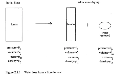
lumen lumen
pressure=P0 volume=V
0 mass=m0 densityip o
water removed
pressure=Pi pressure=P0 volume=V
1 volume=V wr
mass=m
1 mass=m2
densityip density93 2
[image:33.562.65.516.56.362.2]Initial State After some drying
Figure 2.1.1 Water loss from a fibre lumen
Fig. 2.1.1 represents the fibre lumen decreasing in volume as water is removed. V wr is the volume of water removed from the fibre by drying. It is expressed at the starting pressure of 130 for convenience. Note that the fibre lumen is completely filled with water both before and after the drying shown.
increasing negative pressure
[image:33.562.86.516.459.822.2]Volumetric strain Figure 2.1.2 Elastic modulus of water
pressure 130, where V10 is given by: Po—P1 v1
VI0=Vi Ew (2.1.1)
where Ew is the elastic modulus of water. Equation 2.1.1 follows directly from the definition of Ew shown in Fig. 2.1.2.
To conserve mass, we have:
mo = + M2 (2.1.2)
Since density is constant for constant pressure and temperature, we have that
P2 PO (2.1.3)
Substituting 2.1.3 into 2.1.2 and using p=mN we get:
PoVo = PIV1 ±Porcr (2.1.4)
Using (2.1.1) we get:
Polio = Po VI 0 POVwr (2.1.5)
and hence:
Vo = 0 + (2.1.6)
and thus, substituting for V10 from 2.1.6 into 2.1.1, we get: P — P
=V0 —V1(1— ° ) (2.1.7)
The variation with temperature of the elastic modulus of water was taken from Appendix 2 in Vennard & Street (1982). Intermediate values were found by linear interpolation. These data were for water at atmospheric pressure. No values for elastic modulus could be found for water under tension although Dorsey (1968) states that "There is no discontinuity in the value of the compressibility as P changes from positive (=pressure) to negative (=tension)." The water is thus assumed to have the same elastic properties in tension and compression for the range of pressures of interest.
2.2 Elastic isotropic analysis
This discussion gives an outline of elastic analysis of an isotropic thick cylinder (Lame problem) filled with water (an elastic fluid). This analysis can be found in many text books on elasticity, but is included here to provide a background to the following models, and because it has proved beneficial to look at simple models first.
The process has been thought of as follows. As the cell dries out, water moves by diffusion out of the cell. This removal of water induces a negative pressure in the cell lumen. The result of this negative pressure is that the water expands, and the cylinder contracts until they are at equilibrium. During wood drying, this equilibrium will be a dynamic one as water is being continually removed, but is very slow so that the problem is treated as static.
Consider a section of a thick walled cylinder, taken perpendicular to the cylinder's axis. The cylinder has inner radius ri, outer radius r2, internal pressure pi, external pressure p2• An element at radius r is subject to radial displacement u.
d a ar + dr at v---„ . dr
dr \
ar L.%
,Zzr
■
at
Figure 2.2.1 Element in static equilibrium
The components of strain are defined by • du
Cr =- and e, = — • dr
_Generalised Hooke's law for a body is given by
1
er (ar — Pad
1
et = (cr, — Par — Paz) (2.2.2)
1
6- =(o-. E par — Pad
The plane strain approximation (6., = 0) reduces the third of equations 2.2.2 to
Cr: = (2.2.3)
Substituting 2.2.1 into the first two equations of 2.2.2 and solving for or and a, gives cr = (/ + 140 —
2p)
10
et- 4- Peial=
(1+11)(1— 2p)[Per+ — 14 6,]
Using the plane strain assumption, the equation for static (planar) equilibrium of an element of a thick walled cylinder as shown in Fig. 2.2.1 above is
do-r
o-, —a - = u or dr
do-, o-r — o-
+ = 0 (2.2.5)
dr
Substituting 2.2.4 into 2.2.5 yields d2u 1 du u
+--- — = 0 (2.2.6)
dr 2 r dr r 2
Thus the solution A
u= Air +—a- (2.2.7)
gives the radial deflection of a point at radius r, where Ai and A2 are given by boundary conditions.
In this case, it can easily be shown that
1
A _a+ PM— 214 Pir12 — P2r2
— 1 2
A2 =
a ± (pi
—
2 Pdri2r22r2 — 2
(2.2.8)
Thus the internal radius of the cylinder when it is subject to the pressures pi and 132 1S:
r'new = + (2.2.9)
Substituting the solution for u in 2.2.9 gives
(1 + ,u)(1— 2p) pi — p2r22 (I + ((p1 P2)ri2r22) 1 = r
r, , r
• • old r22 — ri2 j1 r22 — /I2 1
•
(2.2.10)where ri and r2 are the new values of the inner and outer radii respectively, and ri old is the old value of ri.
A similar equation exists for r2:
(1+ ,u)(1- 2p) p,r,2 - p2 r22 (1+ 11)(0)1 - P2)T12r22) 1 r2 = r2oh, +
Y22 - 2 ) r2 r22 - ri2 Y2
(2.2.11) Solution of these equations is considerably simplified when the original values of ri and 1.2 are used on the RHS of the equation. This is acceptable for small deflections.
In the specific case of drying timber, the initial cell sizes are known, and the cell wall properties can be inferred from bulk properties. Thus 2.2.10 gives the variation of internal radius with internal pressure of the cylinder (subject of course to the limitations and assumptions mentioned above).
General equations for the radial and tangential stress at any point in the cylinder are easily obtained, and take the form of:
C2
ar = (2.2.12)
and a / = C1 + —2- (2.2.13)
r 2 PI 2 r 2
I' I 1-2' 2
-
r22 - r12 (PI - P2 )/12r22 C2 -
r22 - r12
The convention of tensile stresses being positive, and compressive stresses being negative is used.
2.3 Three layer isotropic analysis
The next complication after the single isotropic layer model is to apply the Lame theory to three layers, corresponding to the Sl, S2, and S3 layers.
,/\ R3 R2\ RI
The layers are labelled Li, L2, and L3 from the outside in. The inner radius is labelled R1, and the outer radius R4. The two interface radii are labelled as R2 and R3.
L2 For each layer, the theory as outlined in LI
the previous section on elastic isotropic Figure 2.3.1 Three layered cylinder analysis applies. It remains to determine the boundary conditions for each layer, so that we may solve for the deflections throughout the cylinder wall. The boundary conditions are stated as:
a r3lri= -p1 ; - internal pressure = radial stress at inside
0
rj =—p2; -
external pressure = radial stress at outside-= ; radial stress at interface r3 is equal in layers 1 and 2
r3 r3
ar 2 r = a r3 2 ; radial stress at interface r2 is equal in layers 2 and 3
ell 1r3 = 612 1r3 • tangential strain at interface r3 is equal in layers 1 and 2
e,2 1r2 = 6
.
13 1 ;
tangential strain at interface r2 is equal in layers 2 and 3r2
U21v3 r3 =U i l ; radial displacement at interface r3 is equal in layers 1 and 2
u31 r2 =
u
2
I •
r2, radial displacement at interface r2 is equal in layers 2 and 314- ri • •
z 1
+r, = r, •
13 ' radial displacement at inner surface plus original inner radius= new inner radius
and writing out the equations for the above boundary conditions we get:
E3
A
(2.3.1)
— (1+ p3)(1-2,u3)
(A
13
-(1 - 23)-
El
(2.3.2)
pi)
(A
"
—
2p1)--)
JEl
(1+ p 2 p2)
(Al2 -
(1 -2/12)N
A
r,
2)E
(1 2
-
A22) (AI,
—(1-2,u1 ) 31—
(1 + I X1 — )
r32
E2 \ A2, E3
1
A13 - (1 2p- 3 (1 p2 X1 -"12
2/12
-
A
-(1 - 2112) r2
A
2p3) r2
(2.3.4) (2.3.5)
(2.3.6)
(2.3.7) r; 12 r32
A22 A A23
+
=
+
2
r2 r2- A23
+ rl = rI
where Aii is the ith deflection equation constant for layer j (equation 2.2.7).
Note that from the given nine boundary conditions, there are only seven used here. The conditions for equality across interfaces of tangential strains and radial displacements are in fact the same conditions, so that of the four equations, two are redundant.
The first six boundary equations, equations 2.3.1 to 2.3.6 are solved for the six coefficients Aii after specifying the internal and external pressures. Equation 2.3.7 then gives the new internal radius, which is used in equation 2.1.7 to calculate the volume of water removed.
The values of A1 and A2 for each layer are then substituted into equation 2.2.7 to solve for the displacements.
2.4 Three layer linear orthotropic analysis
The elastic isotropic model, although simple and easy to implement, is probably not a particularly realistic representation of the real situation. The next complicating step is to extend the model to incorporate orthotropic material properties. To realistically represent the cell wall, the model must incorporate three distinct layers with accompanying different orthotropic properties to represent the Si, S2, and S3 layers. This modification is performed here.
The equations for static equilibrium and strain are the same as for the isotropic case, ,. a,. - =0
du
Er = —
dr
e, = -u and
(2.4.2) (2.4.3)
The three dimensional Hooke's law relationship for an orthotropic material is:
a r 6 Pir — -
E,
6
(2.4.4)
(2.4.5)
(2.4.6)
Sr =
E,.
el
-r
(T-
E,
z = —Ez —
Er -
Where ,uu is defined as the strain in the j direction divided by the strain in the i direction due to a direct stress in the i direction
or = x-
Ei
The plane strain approximation ez = 0 is substituted into 2.4.6 which is then substituted into 2.4.4 and 2.4.5 to give
er =( 1 - Pzritij --Lcr (Pir
E,. E,
• = (pH Pz40 ± -2-cl (1- 11-Huiz)
Er E,
Solving for the stresses we find: Er
ar - - r (Pit- lizrAltz)et]
- (p„ pz, 11,)(11,r + p„p,z)+ (1- pzrp,X1 Az)
(2.4.9) E,
e
— (Uri PzI Prz)(Pir Piz) + ( 1 — 11,7)( 1 Pa) R
± Pz, PJr + (1-
(2.4.10)
These expressions are general for any linearly orthotropic cylindrically symmetric body.
(2.4.7)
(2.4.8)
2.4.1 Material Properties
Relative Stiffness
Timber from Tasmanian eucalypts, like most timbers, is approximately half as stiff in the tangential direction as it is in the radial direction. An explanation for this has been proposed by Ilic (1987). There are many more large thin walled vessels (rays) running in the radial direction than there are in the tangential direction (Ilic, 1991). Radially oriented vessels soften the wood tangentially in proportion to the longitudinal sections of the vessels, whereas the softening of the wood radially is only in proportion to the cross sectional area of the vessels. Thus the wood is softer in the tangential direction than in the radial direction.
The fibres being modelled lie longitudinally in the tree. The fibre cell secondary wall is composed of three layers, labelled the Si, S2, and S3 from the outside in, as described above. These layers are predominantly cellulose in the form of microfibrils. Microfibrils consist of long chain polymers called elementary fibrils, bundled together to form a structural unit which is typically 1 Onm to 30nm wide. The microfibrils are aggregated into macrofibrils, which are organised into lamellae within the different layers of the cell wall. In each of the secondary cell wall layers, the microfibrils are helically wound in a predominant direction. In the Si and S3 layers, the microfibrils are close to perpendicular to the longitudinal axis of the fibre. In the S2 layer the microfibrils are close to parallel to the fibre axis (Siau, 1984).
An earlier investigation (Innes, 1992) into structural properties across the grain of Tasmanian Oak gave a tangential stiffness below the proportional limit at 22°C and MC>FSP of 310MPa. It is assumed that the radial modulus is approximately twice the tangential modulus, and that the longitudinal modulus is approximately twenty times the tangential modulus. Thus, for the cell wall, the values used are: E, = 620 MPa, and Ez = 6.20 GPa.
Poisson's ratios
Linearly elastic orthotropic analyses are based on the existence of a strain-energy function. If such a function does exist, it must be a quadratic function of the stresses, and therefore a quadratic function of the strains, because of the linear stress-strain relationship. Comparison of the function in terms of the stresses with that in terms of the strains leads to the general expression: E„u„ = Epuu (Love, 1944). There are three such equations in the orthotropic case; the Poisson's ratios and Young's moduli have been set up to ensure the satisfaction of these conditions.
The six Poisson's ratios below are taken from the US Forest Products Laboratory "Wood Handbook" (1974). These ratios are for the solid wood form of black walnut, which seems to behave structurally in a similar fashion to Tasmanian eucalypts.
litr = 0 . 379
,uzr = 0.495
,urt = 0.718
,uzt =0.632
durz = 0.052
,utz = 0.035
Where the subscript r refers to the radial direction, t to tangential and z to longitudinal.
Note that the values of the Poisson's ratios are consistent with the relative stiffnesses as described above. That is, ir < Pry, Pzi < htzr
< Plz•
Assuming that the fibre Poisson's ratios are similar to the bulk Poisson's ratios except for the tangential softening effect, we re-label the Poisson's ratios for the S2 layer and put: Ptr =/4r1 Ptra = 0. 38, Pzt = Pzr = Pzrt =0.5 and 'Litz =Prz = Ptrz = 0- 05 . This assumes also that the bulk wood stiffness properties are due mainly to the S2 layer because of its relatively large thickness.
The Si and S3 layers are assumed to consist of tangentially wound microfibrils. Thus, there is a 90° rotation in stiffness properties from the S2 to the Si and S3 layers and there is also a 90° rotation in Poisson's ratios. Hence the radial and longitudinal stiffnesses are assumed to be equal, and hence we use: PZr 7-- PrZ = 0'38 ,
Ptz =Ptr = Ptzr = 0. 5, and pZ =uri Pzrt = 0.05 for the S1 and S3 layers.
2.4.2 Longitudinal symmetry - S2 layer
Substituting 2.4.9 and 2.4.10 into 2.4.1 using 2.4.2 and 2.4.3 and the simplifications introduced above we get:
d2u 1 du u +----
= u (2.4.11)
dr 2 r dr r 2
which is the same expression as derived for isotropic materials. Thus the solution will again be
A
(2.4.12)
r
where A1 and A2 are constants.
The expression for radial stress then simplifies to:
E A EyY - A2
(Tr (2.4.13)
— pyy — 2pxy py, r 2 (1 + pyy )
When we analyse firstly a single layer orthotropic cylinder based on the S2 layer, the boundary conditions will again be 0 r
1
r
=
—
PI and arlrso that we get
(1— P yy 2,u„ypy,)(r22 p2 — rI2 p,
A
)
E y (1.12 _r)
( i PYY ) (P2 - Pi )1'12 r22
A2 -.
E y (r12 _r22)
= — P2
Hence, as for the isotropic case, the deflection based analysis leads to a simple analytic solution for the stresses and strains through the S2 layer considered in isolation. The S2 layer can be treated as part of a multi layered cylinder by changing the boundary conditions to suit.
2.4.3 Tangential symmetry - S1 and S3 layers
The Si and S3 layers consist of microfibrils which are wound around the fibre in a direction which is close to perpendicular to the longitudinal axis of the fibre. This analysis then assumes that the properties of the layer are the same in the radial and longitudinal directions, but different in the tangential direction.
Using a process similar to that above leads to the differential equation (d.e.) for radial deflection, u:
d2u 1 du Pxy (1- Pyy2 U
2 - (2.4.15)
dr2 + r dr— Pyx(1 —
The solution to this d.e. is not nearly so simple as the previous one. That is, the deflection based analysis does not lead to a simple solution. Another form of solution is used to simplify the problem.
Using the plane strain assumption gives the equation for static (planar) equilibrium of an element of a thick walled cylinder as
dcr,. ± ar — cr, .0
(2.4.16) dr
This is used to solve for the stresses in a layer in an incremental fashion when we replace the derivative with finite differences and rearrange to give:
( — )
aCr r = gr r (2.4.17)
To solve for the stresses using this approach, the layer is solved in steps from the inside (where initial conditions are known) to the outside, using a set value of & to give &Tr and hence, the stress and strain conditions at the next step.
compared with the more definitive analytic solution. Boundary conditions between the layers were the same as those used in the multi layer isotropic model.
The result of this comparison was a verification of the incremental solution, which typically differed from the analytic solution by less than 1%. The comparison was made using 20 steps in radius through the S2 layer. This was taken as being sufficient support for the solution through the three layers using the incremental method. The incremental type of solution is used when the model is extended to non linear material behaviour as, in that case, equal increments of stress will not give equal increments of strain at different points on the loading curve.
2.5 Non-linear orthotropic analysis
The fibre wall is modelled as consisting of three layers, all with different non linear orthotropic material properties. This simulates the Si, S2 and S3 layers of the secondary fibre wall, each of which consists principally of helically wound cellulose microfibrils (Siau, 1984) as previously discussed. The primary wall is neglected due to its small thickness and random microfibril direction. The model was implemented as the Turbo Pascal program Cyl_A.pas (see Appendix D for a block diagram).