• No results found

Multiple configuration shell core structured robotic manipulator with interchangeable mechatronic joints : a thesis presented in partial fulfilment of the requirements for the degree of Masters of Engineering in Mechatronics at Massey University, Turitea

N/A
N/A
Protected

Academic year: 2020

Share "Multiple configuration shell core structured robotic manipulator with interchangeable mechatronic joints : a thesis presented in partial fulfilment of the requirements for the degree of Masters of Engineering in Mechatronics at Massey University, Turitea"

Copied!
192
0
0

Loading.... (view fulltext now)

Full text

(1)
(2)
(3)

Multiple Configuration Shell-Core

Structured Robotic Manipulator with

Interchangeable Mechatronic Joints

A thesis presented in partial fulfilment of the requirements for the degree of

Masters of Engineering

in

Mechatronics

at

Massey University, Turitea Campus

Palmerston North

New Zealand

(4)
(5)

Abstract

With the increase of robotic technology utilised throughout industry, the need for skilled labour in this area has increased also. As a result, education dealing with robotics has grown at both the high-school and tertiary educational level. Despite the range of pedagogical robots currently on the market, there seems to be a low variety of these systems specifically related to the types of robotic manipulator arms popular for industrial applications. Furthermore, a fixed-arm system is limited to only serve as an educational supplement for that specific configuration and therefore cannot demonstrate more than one of the numerous industrial-type robotic arms.

The Shell-Core structured robotic manipulator concept has been proposed to improve the quality and variety of available pedagogical robotic arm systems on the market. This is achieved by the reconfigurable nature of the concept, which incorporates shell and core structural units to make the construction of at least 5 mainstream industrial arms possible. The platform will be suitable, but not limited to use within the educational robotics industry at high-school and higher educational levels and may appeal to hobbyists.

Later dubbed SMILE (Smart Manipulator with Interchangeable Links and Effectors), the system utilises core units to provide either rotational or linear actuation in a single plane. A variety of shell units are then implemented as the body of the robotic arm, serving as appropriate offsets to achieve the required configuration. A prototype consisting of a limited number of ‘building blocks’ was developed for proof-of-concept, found capable of achieving several of the proposed configurations.

(6)
(7)

Acknowledgements

I would like to extend a special thanks to my supervisor Liqiong Tang for her invaluable support and guidance throughout. I am very grateful to be part of her vision, in further developing her initial concept, conceptually and from an implementation perspective. Her assistance in helping me attain further financial support in the form of scholarships has been much appreciated and is the reason I am able to pursue this project further. I look forward to working with her in the future.

The contribution Huub Bakker has made to this project has also been noted. His useful control advice has saved me many hours I would have otherwise spent coming to the same conclusion, allowing me to spend my time elsewhere.

Thanks also to Trish O’Grady for the professional standard that she has uphold when ordering parts for the project.

I would also like to thank Will Haarhoff, whom I shared an ‘office’ with. I really enjoyed the occasional project and non-project related discussions. Your contribution may not have been direct, but has certainly helped to shape the outcome.

Thank you to my wife, Katy Johnston, who has been a great source of support. Her unique perspective on technology has influenced this project in ways I would not have considered.

(8)
(9)

Table of Contents

ABSTRACT

III

ACKNOWLEDGEMENTS

V

TABLE OF CONTENTS

VII

LIST OF FIGURES

XI

LIST OF TABLES

XVII

LIST OF ABBREVIATIONS

XIX

CHAPTER 1 INTRODUCTION

1

1.1 Background 2

1.2 Research Topic 3

1.3 Scope of Research 4

1.4 Organisation of Dissertation 5

CHAPTER 2 LITERATURE REVIEW

7

2.1 Background 8

2.2 Market Research - Industrial Robotic Systems 9

2.2.1 SCORBOT-ER 9PRO 9

2.2.2 Kawasaki Industrial Robotics 18

2.3 Market Research - Service Robotics 21

2.3.1 Kinova JACO 21

2.3.2 Bestic 27

2.4 Market Research - Educational Robotics 31

2.4.1 Mecademic DexTAR 31

2.4.2 Mover6 41

2.5 Market Research - Modular Robotics 46

2.5.1 Cublets 46

2.6 Market Research - Price Comparison 53

2.7 Control Methodologies 54

2.7.1 PID Control 54

2.7.2 Cascade PID control 61

2.7.3 Fuzzy Logic Control 62

2.7.4 Fuzzy PID Control 64

2.7.5 Model Based Predictive Control 68

2.7.6 Trajectory Planning 72

2.7.7 Kinematics 74

CHAPTER 3 DESIGN CONSIDERATIONS AND THE PROPOSED

SYSTEM

83

3.1 Shell-Core Concept 84

(10)

3.1.2 Shell Structural Units 87

3.1.3 End-Effectors 88

CHAPTER 4 JOINT ACTUATOR DESIGN

89

4.1 Rotational Actuator System Design 90

4.2 FEA Analysis 93

4.3 Control Componentry (Rotational Actuator) 95

4.3.1 Non-Self-Locking Motor 95

4.3.2 Self-Locking Motor 96

4.3.3 Motor Driver 97

4.3.4 Encoder 98

4.3.5 Micro-Controller 99

4.4 Control Methodologies and Programming (Rotational Actuator) 100

4.4.1 Position Acquisition 100

4.4.2 Communications 102

4.4.3 Velocity Profiling 102

4.4.4 Movement Switch 103

4.4.5 Request Position 104

4.4.6 Clear Error 105

4.4.7 Reset ID 106

4.4.8 Program ID 106

4.4.9 Move to Location 108

4.4.10 Homing Function 112

4.5 Linear Actuator Design 114

CHAPTER 5 ROBOT GRIPPER DESIGN

117

5.1 2-Fingered Gripper Design 118

5.2 Control Componentry (2-Fingered Gripper) 121

5.2.1 Force-Sensing Resistor Square 121

5.2.2 Analogue Infrared Distance Sensor 122

5.2.3 Geared Motor and Encoder 123

5.2.4 Servomotors 124

5.3 Control Methodologies and Programming (2-Fingered Gripper) 125

5.3.1 Main Loop and Position Acquisition 125

5.3.2 Move to Location 126

5.3.3 Homing Function 128

CHAPTER 6 SHELL STRUCTURAL UNIT DESIGN

131

6.1 Shell Structural Design 132

6.2 FEA Analysis 132

CHAPTER 7 COMMUNICATION, POWER SUPPLY AND PCB BOARD

DESIGN

135

7.1 Communications 136

7.2 Power Supply 138

7.3 Control Box 138

7.4 Circuit-Board Design 140

(11)

7.4.2 PCBs in 2-Fingered Gripper 142

CHAPTER 8 IMPLEMENTATION, TESTING AND RESULTS

143

8.1 System Implementation 144

8.1.1 Control Basis 147

8.1.2 2-Fingered Gripper 148

8.2 Control Outcome 149

8.2.1 Rotational Actuator 149

8.2.2 2-Fingered Gripper 157

CHAPTER 9 DISCUSSION, CONCLUSION AND RECOMMENDATIONS159

9.1 Discussion 160

9.2 Conclusion 162

9.3 Recommendations 162

BIBLIOGRAPHY

165

APPENDIX A

MISCELLANEOUS PICTURES A1

A.1 Control Box A1

A.2 Electronics Stand A1

A.3 SCARA A2

(12)
(13)

List of Figures

Figure 1 - 1. London jobs at risk of computerisation. ... 2

Figure 1 - 2. Employer desired skill-sets. ... 3

Figure 1- 3. Basic manipulator arms and the actuators needed to achieve configuration. ... 4

Figure 2 - 1. Scorbot-ER 9Pro picture ... 9

Figure 2 - 2. Scorbase graphical user interface... 10

Figure 2 - 3. Scorbase positional feedback ... 11

Figure 2 - 4. Scorbot coordinate system overviews ... 11

Figure 2 - 5. USB-Pro controller input and output diagram. ... 12

Figure 2 - 6. USB-Pro available control loops. ... 12

Figure 2 - 7. PID control overview. ... 13

Figure 2 - 8. Typical velocity curves ... 13

Figure 2 - 9. Scorbot joint definitions ... 14

Figure 2 - 10. Scorbot workspace ... 14

Figure 2 - 11. Scorbot mounting diagram ... 15

Figure 2 - 12. Motor and motor location diagram ... 15

Figure 2 - 13. Harmonic drive exploded view ... 16

Figure 2 - 14. Encoder signal output, encoder slot, encoder to motor mounting ... 17

Figure 2 - 15. Scorbot actuator cam design cross-section ... 17

Figure 2 - 16. YS002N robot, robot workspace, robot dimensions ... 18

Figure 2 - 17. RS005N robotic arm and workspace ... 19

Figure 2 - 18. CP500L robotic arm and workspace ... 20

Figure 2 - 19. Kawasaki palletising patterns ... 20

Figure 2 - 20. Kinova Jaco picture ... 21

Figure 2 - 21. Kinocare logo. (Kinova Robotics, 2015). ... 22

Figure 2 - 22. Jacosoft NoGo and Slow zone diagram ... 23

Figure 2 - 23. 6 DOF JACO dimensions ... 25

Figure 2 - 24. JACO actuator dimensions ... 25

Figure 2 - 25. Kinova JACO 2-fingered gripper, 3-fingered gripper ... 26

Figure 2 - 26. Bestic picture ... 27

Figure 2 - 27. Bestic diagram ... 28

Figure 2 - 28. Bestic spoon attachment diagram ... 28

Figure 2 - 29. Bestic plate workspace diagram ... 28

Figure 2 - 30. Bestic Picasso MINI ... 29

Figure 2 - 31. Bestic control display diagram. ... 29

Figure 2 - 32. Bestic control step mode diagrams ... 30

Figure 2 - 33. Mecademic DexTAR picture ... 31

Figure 2 - 34. Mecademic DexTAR control screenshots ... 32

Figure 2 - 35. Various DexTAR assembly mode diagrams ... 33

Figure 2 - 36. DexTAR magnetic attachment, pen attachment ... 34

Figure 2 - 37. DexTAR simulation software overview ... 34

Figure 2 - 38. DexTAR Sim interface screenshot ... 35

Figure 2 - 39. DexTAR Sim jogging menu screenshot ... 35

Figure 2 - 40. Mecaprol G-code screenshot ... 35

Figure 2 - 41. DexTAR Inverse kinematic mathematical definitions ... 36

Figure 2 - 42. DexTAR Direct kinematics mathematical definitions ... 38

(14)

Figure 2 - 44. DexTAR singularity positions ... 40

Figure 2 - 45. Mover6 picture ... 41

Figure 2 - 46. CProg GUI screenshot ... 42

Figure 2 - 47. CProg XYZ coordinate control ... 42

Figure 2 - 48. Mover6 end-effector coordinate control screenshot ... 42

Figure 2 - 49. CProg graphical command chain ... 43

Figure 2 - 50. CProg TextEdit window ... 44

Figure 2 - 51. Mover6 operational picture ... 44

Figure 2 - 52. Mover6 mounting diagram ... 45

Figure 2 - 53. Cublets system picture ... 46

Figure 2 - 54. Cublets studio screenshot ... 49

Figure 2 - 55. Various Cublets mobile app screenshots, Cublets logo ... 50

Figure 2 - 56. Drive cube ... 51

Figure 2 - 57. Rotate cube ... 51

Figure 2 - 58 Passive cube ... 51

Figure 2 - 59. Passive cube contact diagram ... 52

Figure 2 - 60. PID control loop diagram ... 54

Figure 2 - 61. PID algorithm ideal form ... 54

Figure 2 - 62. PID algorithm standard form ... 54

Figure 2 - 63. First order transfer function with dead time ... 55

Figure 2 - 64. Tuning table and error percentage calculation ... 56

Figure 2 - 65. Dynamic model of DC motor ... 57

Figure 2 - 66. Simplification by variable definition of dynamic DC motor model ... 58

Figure 2 - 67. Adaptive learning controller formula, applied motor voltage as output ... 58

Figure 2 - 68. Feedback learning input component ... 58

Figure 2 - 69. Error system definition ... 58

Figure 2 - 70. Target characteristic equation and PID gain definitions ... 59

Figure 2 - 71. Error system from target characteristic equation ... 59

Figure 2 - 72. Final error system ... 59

Figure 2 - 73. Learning rules as defined by Seung-Min & Tae-Yong ... 59

Figure 2 - 74. Various control responses ... 60

Figure 2 - 75. Cascade PID control loop diagram ... 61

Figure 2 - 76. Fuzzy logic linguistic membership function ... 62

Figure 2 - 77. Gaussian membership function ... 62

Figure 2 - 78. Triangular membership function ... 62

Figure 2 - 79. Fuzzy logic controller diagram... 63

Figure 2 - 80. Centroid de-fuzzification equation ... 63

Figure 2 - 81. Membership function ... 64

Figure 2 - 82. Fuzzy rule set ... 65

Figure 2 - 83. Error and error derivative equations ... 65

Figure 2 - 84. Resulting control surfaces ... 65

Figure 2 - 85. Fuzzy PI control set-point response ... 66

Figure 2 - 86. Proportional and integral gain responses ... 66

Figure 2 - 87. FLC PI vs. Classical ZM PI set-point response ... 66

Figure 2 - 88. Integral term calculation ... 67

Figure 2 - 89. Controller 3rd order response ... 67

Figure 2 - 90. Mathematical model of manipulator arm ... 68

Figure 2 - 91. Uncertainty definitions... 69

Figure 2 - 92. Manipulator arm equation with added uncertainty ... 69

(15)

Figure 2 - 94. Robust control law defined by Merabet & Gu ... 69

Figure 2 - 95. Final dynamic nonlinear model of robotic manipulator ... 69

Figure 2 - 96. Output vector definition... 70

Figure 2 - 97. General form cost function definition ... 70

Figure 2 - 98. Final predictive model ... 70

Figure 2 - 99. Reference trajectory analysis equation definition ... 70

Figure 2 - 100. Predicted error calculation ... 71

Figure 2 - 101. Expanded general form of cost function ... 71

Figure 2 - 102. Tracking error-based cost function ... 71

Figure 2 - 103. Model based predictive control diagram ... 71

Figure 2 - 104. Controller joint set-point response diagrams ... 72

Figure 2 - 105. Various part collision avoidance methods ... 73

Figure 2 - 106. Local and global collision avoidance diagram ... 73

Figure 2 - 107. Object detection image analysis output ... 73

Figure 2 - 108. Dynamic path planning loop diagram ... 74

Figure 2 - 109. Motion parameter definitions ... 74

Figure 2 - 110. Forward kinematic reference coordinate frame definitions for a cylindrical robot ... 75

Figure 2 - 111. Denavit-Hartenberg Convention and associated definitions ... 76

Figure 2 - 112. Relative coordinate frame definitions ... 77

Figure 2 - 113. Inverse kinematic projection ... 79

Figure 2 - 114. Singularity position ... 79

Figure 2 - 115. Left above arm, right above arm configurations ... 80

Figure 2 - 116. Left and right arm configuration mathematical definitions ... 80

Figure 2 - 117. Elbow up, elbow down configurations and mathematical definitions ... 81

Figure 2 - 118. Left below arm, right below arm configurations ... 81

Figure 2 - 119. Cosine law and corresponding coordinate definitions ... 82

Figure 3 - 1. Actuator planes of motion ... 86

Figure 3 - 2. Cylindrical configuration with passive block ... 86

Figure 3 - 3. Shell Structural Units ... 87

Figure 3 - 4. 2-Fingered gripper pictures ... 88

Figure 3 - 5. PUMA realised with gripper addition ... 88

Figure 4 - 1. Various rotational actuator drive pictures ... 90

Figure 4 - 2. Rotational actuator electronics and drive shaft pictures ... 90

Figure 4 - 3. Rotational actuator homing cam ... 91

Figure 4 - 4. Mid-point position (Corresponds to Table 4 – 1) ... 91

Figure 4 - 5. Encoder position ... 92

Figure 4 - 6. Rotational actuator end covers ... 92

Figure 4 - 7. Programming openings ... 92

Figure 4 - 8. Resultant exaggerated displacement diagrams (0.0058 mm max) ... 93

Figure 4 - 9. Resultant exaggerated stress diagrams (50.2 MNm2 max) ... 94

Figure 4 - 10. Polulu 99:1 metal gearmotor MP 12V ... 95

Figure 4 - 11. Polulu 99:1 metal gearmotor HP 12V ... 96

Figure 4 - 12. Polulu G2 High-Power motor driver 24v13 ... 97

Figure 4 - 13. Polulu G2 24v13 driver current limit reference ... 97

(16)

Figure 4 - 15. Encoder output ... 98

Figure 4 - 16. Microcontroller pinouts ... 99

Figure 4 - 17. Main loop function ... 100

Figure 4 - 18. readPos() function ... 101

Figure 4 - 19. Position calculation code snippet ... 101

Figure 4 - 20. Communication interrupt code snippet ... 101

Figure 4 - 21. Receive communications code snippet ... 102

Figure 4 - 22. Velocity profiling code snippets ... 102

Figure 4 - 23. setVelProfile() function ... 103

Figure 4 - 24. Movement switch code snippet ... 103

Figure 4 - 25. Disable movement code snippet ... 103

Figure 4 - 26. Request position code snippets ... 104

Figure 4 - 27. communicatePos() function ... 104

Figure 4 - 28. Clear error code snippets ... 105

Figure 4 - 29. errorHandler() function ... 105

Figure 4 - 30. Reset ID code snippets... 106

Figure 4 - 31. Program ID code snippets ... 106

Figure 4 - 32. getMountType function ... 107

Figure 4 - 33. New ID code snippet ... 107

Figure 4 - 34. transmitID() function ... 107

Figure 4 - 35. AssignNextID function ... 108

Figure 4 - 36. Receive movement command code snippets ... 109

Figure 4 - 37. locate() function code snippet ... 109

Figure 4 - 38. Scaled position calculation code snippet ... 110

Figure 4 - 39. Deadband calculation code snippet ... 110

Figure 4 - 40. Output minimum set code snippet ... 110

Figure 4 - 41. PWM output and smoothed output calculation code snippets ... 111

Figure 4 - 42. Write PWM value to motor code snippet ... 111

Figure 4 - 43. Homing function code snippets ... 112

Figure 4 - 44. initialize() function ... 112

Figure 4 - 45. Homing fuzzy rules code snippet ... 113

Figure 4 - 46. Homing error tester code snippet ... 113

Figure 4 - 47. Post homing code snippet ... 113

Figure 4 - 48. Physical home position ... 113

Figure 4 - 49. Linear actuator design ... 114

Figure 4 - 50. Liner actuator support bearings and lead nut ... 114

Figure 4 - 51. Linear actuator home switch ... 115

Figure 5 - 1. Fingered gripper extension travel ... 118

Figure 5 - 2. 2-Fingered gripper pictures ... 118

Figure 5 - 3. 2-Fingered gripper section ... 119

Figure 5 - 4. PUMA configuration with gripper, articulated configuration with gripper .... 119

Figure 5 - 5. 2-Fingered gripper end rotational axis ... 120

Figure 5 - 6. Square FSR picture, FSR resistance vs. force diagram ... 121

Figure 5 - 7. Analogue infrared picture, sensor voltage vs. distance diagram ... 122

Figure 5 - 8. 9.7:1LP Gearmotor, worm gear mechanism ... 123

Figure 5 - 9. Gearmotor encoder, encoder output, encoder colour functions ... 123

Figure 5 - 10. YM-2763 picture ... 124

(17)

Figure 5 - 12. readEncoder() function code snippet and corresponding PWM signal ...126

Figure 5 - 13. locateGripper() function condition code snippet ...126

Figure 5 - 14. Movement communication set-point change code snippet ...127

Figure 5 - 15. locateGripper() function ...128

Figure 5 - 16. initialize() function ...129

Figure 6 - 1. Resultant exaggerated vertical stress diagrams (20 MNm2 max) ...133

Figure 6 - 2. Resultant exaggerated vertical displacement diagrams (0.6 mm max) ...133

Figure 6 - 3. Resultant exaggerated twist stress diagrams (34 MNm2 max) ...134

Figure 6 - 4. Resultant exaggerated twist displacement diagrams (1.6 mm max top, 0.4 mm max bottom) ...134

Figure 7 - 1. Communications diagram ...136

Figure 7 - 2. XT60 power connector ...138

Figure 7 - 3. Control box components ...139

Figure 7 - 4. Arduino Uno ...139

Figure 7 - 5. Rotational actuator rotational electronics mount ...140

Figure 7 - 6. Motor driver board PCB and schematic ...140

Figure 7 - 7. Power board PCB and schematic ...141

Figure 7 - 8. Slave wiring board PCB and schematic ...141

Figure 7 - 9. Slave wiring board PCB and schematic ...142

Figure 7 - 10. Gripper power board PCB and schematic ...142

Figure 7 - 11. Gripper slave wiring board PCB and schematic ...142

Figure 8 - 1. System function diagram ...144

Figure 8 - 2. Final prototype parts ...144

Figure 8 - 3. SCARA displacement test definitions ...145

Figure 8 - 4. Realised configurations ...145

Figure 8 - 5. Aluminium test rig ...146

Figure 8 - 6. Sending 'P,' to master controller (SCARA configuration removed from base with gripper) ...147

Figure 8 - 7. Implemented 2-Fingered gripper ...148

Figure 8 - 8. Raw output (2000 samples) ...149

Figure 8 - 9. Rolling average of 30 output (2000 samples) ...149

Figure 8 - 10. Typical PWM response in response to set-point change (918 samples) ...150

Figure 8 - 11. Self-locking (R VP1) - moving to home location (437 samples) ...151

Figure 8 - 12. Steady-state error (200 samples) ...151

Figure 8 - 13. Set-point change response (1011 samples) ...152

Figure 8 - 14. Non-self-locking (r VP1) (431 samples) ...153

Figure 8 - 15. Steady-state error (748 samples) ...153

Figure 8 - 16. Set-point change response (1033 samples) ...154

Figure 8 - 17. Set-point change PWM response (918 samples) ...154

Figure 8 - 18. Large random disturbances, little time to settle (1043 samples) ...155

Figure 8 - 19. Large disturbances PWM response (corresponds to fig) ...155

Figure 8 - 20. Small random disturbances, little time to settle (932 samples) ...156

Figure 8 - 21. Gripper set-point change (688 samples) ...157

(18)

Figure 9 - 1. Introduced nonlinearities ... 160

Figure 9 - 2. Gear lash diagram ... 161

Figure 9 - 3. Proposed harmonic drive assembly ... 163

(19)

List of Tables

Table 2 - 1. Scorbot specifications. (Intelitek, 2008, p.13). ... 10

Table 2 - 2. USB-Pro specifications. (Intelitek, 2008, p.13-14) ... 12

Table 2 - 3. Scorbot joint actuation specifications. (Intelitek, 2008, p.13). ... 14

Table 2 - 4. Scorbot motor axes properties. (Intelitek, 2008, p.32). ... 16

Table 2 - 5. Scorbot axes gear ratios. (Intelitek, 2008, p.35). ... 17

Table 2 - 6. YS002N specifications. (Kawasaki, 2015, p.3) ... 18

Table 2 - 7. RS005N specifications. (Kawasaki, 2015, p.3). ... 19

Table 2 - 8. CP500L specifications. (Kawasaki, 2015, p.9) ... 20

Table 2 - 9. Kinova Jaco arm specifications. (Kinova Robotics, 2014, p.4)... 21

Table 2 - 10. Kinova Jacosoft available packages. (Kinova Robotics, 2015). ... 23

Table 2 - 11. Kinova actuator specifications. (Kinova Robotics, 2015). ... 24

Table 2 - 12. Bestic specifications. (Bestic AB, 2015) ... 27

Table 2 - 13. Mecademic DexTAR specifications. (Mecademic, 2014, p.2) ... 31

Table 2 - 14. Mover6 specifications. (Commonplace Robotics, 2016) ... 41

Table 2 - 15. Graphical command chain button definitions.. ... 43

Table 2 - 16. Cublet type definitions. (Modrobotics, 2012). ... 47

Table 2 - 17. Ziegler-Nichols gain settings. (Microstar Laboratories). ... 55

Table 2 - 18. Revolute and Pismatic graphical representation. (Hydzik, 2004). ... 74

Table 3 - 1. Basic manipulators and the actuators needed to achieve configurations. ... 84

Table 3 - 2. Basic types of actuator. ... 85

Table 3 - 3. Configurations realised with the proposed system (no end-effector). ... 85

Table 3 - 4. Other configurations. ... 85

Table 4 - 1. Rotational actuator rotational positions. ... 91

Table 4 - 2. Rotational actuator specifications. ... 92

Table 4 - 3. Material: 6061 Aluminium alloy properties. ... 93

Table 4 - 4. Polulu 99:1 MP gearmotor specifications. ... 95

Table 4 - 5. Polulu 99:1 HP gearmotor specifications. ... 96

Table 4 - 6. Polulu G2 24v13 driver specifications. ... 97

Table 4 - 7. MAE3 encoder specifications. ... 98

Table 4 - 8. Arduino micro specifications. ... 99

Table 5 - 1. Square FSR specifications ... 121

Table 5 - 2. Analogue infrared sensor specifications. ... 122

Table 5 - 3. 9.7:1 Gearmotor specifications. ... 123

Table 5 - 4. YM-2763 servomotor specifications. ... 124

Table 6 - 1. Material: 6061 Aluminium alloy properties. ... 132

Table 6 - 2. Material: ABS properties. ... 133

Table 7 - 1. Communications definitions. ... 136

(20)

Table 7 - 3. Total number of IDs and their corresponding usage. ... 137

Table 7 - 4. Actuator type designators. ... 137

Table 7 - 5. General communications protocols. ... 138

Table 7 - 6. 150 W power supply specifications. ... 139

Table 7 - 7. Arduino Uno specifications. ... 139

Table 8 - 1. Prototype element weights ... 145

Table 8 - 2. Measured SCARA displacement ... 145

Table 8 - 3. Tested configurations and transition times. ... 146

Table 8 - 4. Approximate gripping strength... 148

Table 8 - 5. Approximate gripper tracking speed. ... 148

(21)

List of Abbreviations

3D: 3-Dimensional

CAD: Computer Aided Design

CAM: Computer Aided Manufacturing CAN: Controller Area Network CD: Compact Disc

CMY: Cyan Magenta Yellow

CNC: Computer Numerical Control CPR: Commonplace Robotics DC: Direct Current

DOF: Degrees Of Freedom FEA: Finite Element Analysis FSR: Force Sensing Resistor GUI: Graphical User Interface HP: High-Power

I2C: Inter-Integrated Circuit ID: Identification

IO or I/O: Input Output LED: Light Emitting Diode LSC: Laser Slit-scan Camera

MOSFET: Metal-Oxide Semiconductor Field-Effect Transistor MP: Medium-Power

MPC: Model based Predictive Controller MTTR: Mean Time To Repair

PC: Personal Computer PCB: Printed Circuit Board PI: Proportional Integral

PIC: Peripheral Interface Controller PID: Proportional Integral Derivative PSU: Power Supply Unit

PUMA: Programmable Universal Machine for Assembly PWM: Pulse Width Modulation

RGB: Red Green Blue

ROS: Robotic Operating System RPM: Revolutions Per Minute

SCARA: Selective Compliance Assembly Robot Arm SDA: Serial Data Line

SLC: Serial Clock Line

SMILE: Smart Manipulator with Interchangeable Links and Effectors SMT: Surface Mounted Technology

STEM: Science, Technology, Engineering and Mathematics TITO: Two Input Two Output

UK: United Kingdom US: United States

(22)
(23)

Chapter 1

Introduction

1.1 Background 2

1.2 Research Topic 3

1.3 Scope of Research 4

(24)

1.1 Background

Robotic manipulators have been an ever-growing aspect of industry since the robotic-industrial relationship was first documented in 1937, when the earliest known robotic-industrial robot was completed by ‘Bill’ Grifith P. Taylor, published in Meccano Magazine (Meccano Ltd, 1938, p.172). The first robotic patents were applied for in 1954 by George Devol, who later co-founded Unimation with Joseph F. Engelberger, installing GM’s first spot-welding robots in 1969 (IFR Germany, 2012). Unimation later licensed their technology to Kawasaki Heavy Industries and GKN, resulting in what would later be referred to as the Japanese ‘robot boom’, peaking in 1984.

In 2006, the Japanese government estimated its robotic industry to be worth about $US 5.2 billion, further increasing to $US 26 billion in 2010. According to Tabuchi 2008, this figure is expected to rise to $US 70 billion by 2025. This translates to over 370,000 operational industrial robots in 2005, with the Japanese Trade Ministry calling for 1 million industrial robots to be installed throughout the country be 2025.

[image:24.595.73.469.355.632.2]

In an article by Kowles-Cutler et al. (2014), it is concluded that 35 per cent of today’s jobs in the UK and 30 per cent in London are at high risk of becoming non-existent within the next two decades as a result of the impact of computers and robotics (fig. 1-1).

Figure 1 - 1. London jobs at risk of computerisation. (Kowles-Cutler, et al., 2014). Copyright 2014 by Deloitte.

(25)

Although over 800,000 jobs have been lost over this period, approximately 3.5 million have been created as a direct result of automation and computerisation (Kowles-Cutler, at al., 2014), with new jobs annually paying on average £10,000 more than their predecessor, boosting the net economy by approximately £140 billion. As a result, the skillsets prioritised by London business employers have shifted (fig. 1-2).

Figure 1 - 2. Employer desired skill-sets. (Kowles-Cutler, et al., 2014). Copyright 2014 by Deloitte.

As a result of the influx of robotics and automation in industry, the presence of robotics-related schooling has significantly increased at secondary and tertiary educational institutes around New Zealand, with Massey University first offering a Mechatronics Engineering degree in 1999. This has provided a stable platform for pedagogical robotic products at the high-school level, most popularly Vex Robotics. Vex introduces students to robot-like design aspects and implementation and encourages the type of generalised critical thinking required for robotic problem solving, however this does not expose the user to industrial-type manipulator arms.

Although a fixed-arm robotic system can be very useful serving as an education supplement, the scholastic value of such a system is limited to the robotic theory relating to the specific manipulator arm and therefore cannot physically demonstrate more than one of the varying types of arms currently popular for industrial use. This gained insight seemed to suggest a potential market gap and lead to the development of the reconfigurable robotic arm concept.

The Shell-Core Structured Robotic Manipulator Arm concept aims to incorporate modularity to the extent that all mainstream manipulator arms may be constructed with the system through the use of two types of actuators, linear and rotational.

1.2 Research

Topic

(26)

1.3 Scope of Research

The scope of this research extends to the development of a prototype for the purpose of investigating the viability and methodologies surrounding the related physical implementation aspects of a robotic manipulator system that is flexible enough for mainly robotic manipulator pedagogical purposes.

x Investigate the current pedagogical robotic manipulator market and understand the limitations and drawbacks for future robotic education. Study the configurations offered by the current educational robotic industry. Research the available control methodologies used by educational robotic manipulator systems. x Propose a robotic system that could better meet the current demand on robotic learning. Although fixed manipulator arms can help teach underlying robotic theory, they are inherently limited to only expose the user to that specific type of robot and therefore cannot physically demonstrate the multiple types of arms currently popular for industrial use. The proposed outcome of this research may be very useful in serving as a supplement for robotics education.

x Design an initial system platform capable of achieving different robotic manipulator configurations, flexible enough to accommodate for varying effectors. x Design and implement an end-effector gripper for the proposed system.

x Develop a robust control basis for the proposed robotic system, which may allow for future advanced control of multiple elements acting in unison.

x Develop a physical prototype of the proposed robotic system for proof-of-concept, capable of achieving at least 2 configurations.

The initial concept includes two types of actuators, prismatic and revolute, with each providing either linear or rotational motion respectively. Structural units will also be included to inter-connect these actuators, providing the offsets needed to produce the required configurations, eg: 90° bend, straight off-set connection, flipped straight off-set connection. Varying end-effectors may be included depending on application, eg: electro-magnetic, 2-fingered gripper, 3-fingered gripper, drawing utensil attachment. Passive actuators may also be considered.

Cartesian SCARA Cylindrical Spherical

(Polar)

Articulated

3 linear 1 linear 2 rotational 2 linear 1 rotational 1 linear 2 rotational 3+ rotational

Figure 1- 3. Basic manipulator arms and the actuators needed to achieve configuration. (Meier, 2016).

(27)

correlating to its specific dimensions, which are passed along to the control unit that will automatically adjust its control methodology to suit the unique configuration.

1.4 Organisation

of

Dissertation

This dissertation contains nine chapters and one appendix. Each of the following passages briefly describes the contents of each chapter or appendix in this thesis.

Chapter 1 provides brief context and outlines the introduction and scope of research.

Chapter 2 presents and studies relevant products currently popular for use in a robotics related educational field. This chapter also includes applicable control methodologies, examining the way in which common control problems have been solved in the past.

Chapter 3 details the Shell-Core reconfigurable manipulator concept at the core of this thesis.

Chapter 4 focuses on Core-type components, covering their design, componentry and programming implementation.

Chapter 5 covers the 2-fingered gripper design, componentry used and programming control methodologies.

Chapter 6 describes Shell-type structural design considerations.

Chapter 7 covers the implemented system communication protocols and provides design and componentry details relating to the control box and circuit-boards.

Chapter 8 provides details regarding the final produced prototype in terms of the physical outcome and control results.

Chapter 9 discusses the novelty of the proposed concept, control difficulties and prototype advantages and disadvantages. This chapter also discusses the viability for future development of the prototype and concept.

(28)
(29)

Chapter 2

Literature

Review

2.1 Background 8

2.2 Market Research - Industrial Robotics 9

2.3 Market Research - Service Robotics 21

2.4 Market Research - Educational Robotics 31

2.5 Market Research - Modular Robotics 46

2.6 Market Research - Price Comparison 53

(30)

2.1 Background

The nature of this project may be described as a combination of new product development and the evaluation of the viability and practical implementation requirements of a reconfigurable, modular robotic manipulator for pedagogical purposes. As such, market research is crucial and key in determining novelty of the proposed concept. Since it is intended that this concept will eventuate into a product, the purpose of the literature review in this context is to assess not only design aspects of products on the market, but their accompanying documentation and consumer related support as well.

Fine manipulator control is very important for robotic applications, therefore a large focus has been put on examining the way in which relevant control problems have been solved by others. Future control additions have also briefly been touched upon, to assure the final prototype system is capable of supporting further advanced control.

(31)

2.2 Market Research - Industrial Robotic Systems

[image:31.595.271.379.123.265.2]

2.2.1 SCORBOT-ER 9PRO

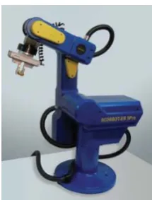
Figure 2 - 1. Scorbot-ER 9Pro picture. (Intelitek, 2008).

Intelitek is a privately owned company originating from Derry, New Hampshire. Founded in 1982, the company has since spread worldwide, with customers in North America, South America, Europe, Asia, the Middle East and Australia. With a strong concentration on pedagogical technology, Intelitek has immersed itself in fields that include engineering, robotics, advanced manufacture, automation, agriculture and STEM, providing systems which cater to CAD / CAM, robotics and machine vision learning.

In 2002, Intelitek provided a $350,000 USD grant to Gilbert High School, Arizona, installing a state-of-the-art robotics lab in the school’s former wood work shop. Intelitek is also heavily involved in VEX, sponsoring the world championship in 2011. Despite the strong educational aspect to the company, some of the available products meet industry standards and thus, are used for such purposes. The Scorbot-ER 9Pro is one of those robots. This system offers advanced path control, speed and accuracy, resulting in major industrial uses including CNC machining, CNC routing and most popularly, laser engraving. At a cost of approximately $20,000 USD, this system sits at the high end of the price spectrum for educational robots. However, as far as industrial robotics is concerned, this system is extremely cost-effective.

All Scorbot manipulator arms function through the use of the Intelitek USB-PRO controller, enabling multi-tasking, real time control and synchronisation of up to 8 axes. 16 digital IO and 4 analogue IO are included (Intelitek, 2008, p.13). While the Scorbot-ER 9PRO integrates with industry-standard robotic control software, Intelitek includes proprietary software with each purchase. SCORBASE is a graphically orientated control and simulation software package that allows arm manipulation through the use of 3D control methodologies.

(32)

Weight 54.4 kg

Speed 1.9 ms-1

Operating radius 691 mm

Payload (Full acceleration) 2 kg Payload (Reduced acceleration) 5 kg

Repeatability ± 0.05 mm

Positional feedback Optical encoders

Table 2 - 1. Scorbot specifications. (Intelitek, 2008, p.13).

Scorbase

Scorbase is a proprietary software package which works in conjunction with the Intelitek USB-PRO controller through the USB interface to control the connected robotic manipulator arm. It should be noted that the control methodology implemented is not graphically orientated. A pseudo-spreadsheet command-line is used to determine movement instructions with each cell containing values relating to arm manipulation.

Figure 2 - 2. Scorbase graphical user interface. (Intelitek, 2009).

(33)

Figure 2 - 3. Scorbase positional feedback. (Intelitek, 2009).

The programming package allows for two homing features. ‘Search Home’ is the procedure for homing, which moves all axes to home position and initialises encoder counts. The ‘Go Home’ command simply moves all axes back to home position; however the encoder count remains unchanged. Peripherals and individual axes may be homed separately. Scorbase supports two coordinate systems, Cartesian (X,Y,Z) and joint angle positions (Intelitek, 2009, p.40).

Figure 2 - 4. Scorbot coordinate system overviews. (Intelitek, 2009).

The ‘Robot Movement’ command dialogue box (fig. 2 - 4) allows for real-time movement of the manipulator arm by the user, both joint angle and Cartesian coordinates are adjustable. It should be noted that there is no mention of any singularity / collision control throughout the user manual accompanying Scorbase. All 20 input and output pins on the USB-PRO controller are also programmable through the use of the spreadsheet style programming language.

USB-PRO Controller

(34)

Figure 2 - 5. USB-Pro controller input and output diagram. (Intelitek, 2008).

Servo axis drivers 8

Path control Joint, linear, circular Speed control 10 speed settings

Power usage 1000 W

Weight 7.5 kg

Digital IO 16

Analogue IO 4

Table 2 - 2. USB-Pro specifications. (Intelitek, 2008, p.13-14).

Figure 2 - 6. USB-Pro available control loops. (Intelitek, 2008).

(35)

Figure 2 - 7. PID control overview. (Intelitek, 2008).

[image:35.595.174.515.70.297.2]

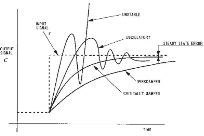
A control loop is used to determine fine motor control and provide smoother manipulator arm movement. The entire control cycle takes roughly 10ms (Intelitek, 2008, p.49). A pulse width modulation (PWM) signal is produced as the output signal, with encoder positions as the input. Proportional, integral, differential (PID) control is used, with all values configurable by the user.

Figure 2 - 8. Typical velocity curves. (Intelitek, 2008).

(36)

Design Aspects

Figure 2 - 9. Scorbot joint definitions. (Intelitek, 2008).

The Scorbot-ER 9PRO is a vertically articulated robot. The base actuator (fig. 2 - 9) allows for rotational movement up to 270° (Intelitek, 2008, p.13). The range of this joint is quite important as it is a large factor in determining the total workspace. The shoulder joint (fig. 2 - 9) is capable of 145° of actuation. This joint, in conjunction with the elbow joint increases total reach of the arm. This also allows the arm to manipulate to an area underneath the robot (fig. 2 - 10), which may be beneficial in certain industrial scenarios.

Axis Range Effective Speed Maximum speed

1 - Base rotation 270° 80°/sec 140°/sec

2 - Shoulder rotation 145° 69°/sec 123°/sec

3 - Elbow rotation 210° 77°/sec 140°/sec

4 - Wrist pitch 196° 103°/sec 166°/sec

5 - Wrist roll 737° 175°/sec 300°/sec

Table 2 - 3. Scorbot joint actuation specifications. (Intelitek, 2008, p.13).

Figure 2 - 10. Scorbot workspace. (Intelitek, 2008).

Workspace is quite important as it determines the effective usefulness of a robotic manipulator arm. Generally, it is useful to have a large workable area directly in front of the robot which is not hindered by singularity or arm collision limitations.

(37)

surface area to cater to the constantly changing momentum of the robot. Allowing three bolts for fastening also helps to distribute the load of the robot.

Figure 2 - 11. Scorbot mounting diagram. (Intelitek, 2008).

A mounting bolt for the cable clamp is also provided (fig. 2 - 11). This is useful to secure the robot cable which leads to the controller. Connectivity of the manipulator arm to the controller is relatively simple. One D37 connector, one D50 connector and a ground cable lead from the robot and connect with the controller. Each connector is unique. Once the robot has been linked and the controller has been interfaced correctly with a PC, via USB and Scorbase, it is a simple matter performing a ‘Hardware Check’ (Intelitek, 2008, p.20). If there are no errors in hardware, the robot may be operated as usual after homing. The gripper mount consists of six M4 mounting bolts, integrated with an 88mm diameter flange. Both power (24V) and pneumatic sockets are located at the top of the ‘forearm’ link (fig. 2 - 10).

There are three main elements to the Scorbot-ER 9PRO drive system (fig. 2 - 12). These include a permanent magnet DC motor, harmonic drive gear and timing belt and pulleys (Intelitek, 2008, p.29). Each robotic manipulator arm contains five of these drive systems, however they may vary individually to suit their specific actuation requirements.

Figure 2 - 12. Motor and motor location diagram. (Intelitek, 2008).

(38)

Motor Axes 1,2,3 Motor Axes 4,5 Peak rated torque 143 oz-in (10.3 kg-cm) 27.8 oz-in (2.00 kg-cm)

Rated torque 32 oz-in (2.30 kg-cm) 12.5 oz-in (0.90 kg-cm)

Maximum operating speed 4000 rpm 4500 rpm

Weight 1.29 kg 0.28 kg

Table 2 - 4. Scorbot motor axes properties. (Intelitek, 2008, p.32).

[image:38.595.173.364.275.409.2]

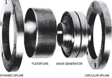
The harmonic drive gear consists of a circular spline, wave generator, flexspline and dynamic spline (Intelitek, 2008, p.33). The flexspline (fig. 2 - 13) has two more teeth than the circular spline, which only mesh once the wave generator forces these to interlock. This means that for one complete clockwise rotation of the wave generator, the flexspline moves anti-clockwise by two teeth. The dynamic spline couples directly with the flexspline.

Figure 2 - 13. Harmonic drive exploded view. (Intelitek, 2008).

For every revolution of input shaft, output shaft will rotate by of a revolution from harmonic gear drive (Intelitek, 2008, p.34).

= 12 =

2

=

= ×

= Harmonic gear ratio = Number teeth flexspline = Belt drive ratio

= Overall effective gear ratio of axis

Axis 1 1.33 : 1 160 : 1 213.33 : 1

Axis 2 1.52 : 1 160 : 1 243.8 : 1

(39)

Axis 4 1.8 : 1 100 : 1 180 : 1

Axis 5 100 : 1 100 : 1

Table 2 - 5. Scorbot axes gear ratios. (Intelitek, 2008, p.35).

The rotational movement of each axis is measured by an optical encoder. Each DC motor is of such design that the drive shaft extends past the motor itself, allowing for the encoder disk to couple directly onto the shaft at one end without hindering rotation at the other end (fig. 2 - 14). Each encoder uses a single light emitting diode (LED). Opposite the LED is a light detecting integrated circuit containing photodetectors and componentry to produce a digital signal. A perforated, rotating disc (fig. 2 - 14) is located between the emitter and detector circuit. As the disc rotates, the beam of light from the LED is broken, which can be detected and thus, create a digital signal (fig. 2 - 4) which is dependent on rotational movement of the motor. Each encoder has 512 slots generating 2048 counts per revolution, allowing for a final resolution of 0.000825° (Intelitek, 2008, p.39).

Figure 2 - 14. Encoder signal output, encoder slot, encoder to motor mounting. (Intelitek, 2008).

Axes 1-4 each contain two limit switches (fig. 2 - 15). Axis 5 does not, which means that it may rotate indefinitely, but is bounded by software control. Limit switches are located at the end of arm travel (fig. 2 - 15) in both directions, right before the hard stops. This allows for maximum actuation of the arm.

Figure 2 - 15. Scorbot actuator cam design cross-section. (Intelitek, 2008).

(40)

software protocol is also in effect (Intelitek, 2008, p.41), which is based on encoder counting, cutting power once a collision has been detected. An optical home switch (fig. 2 - 15) has been implemented in each axis to identify a fixed reference, allowing for a consistent home position.

2.2.2 Kawasaki Industrial Robotics

Because of the size and scope of Kawasaki, there is very little information regarding internal componentry or design of their robotic manipulators. Understandably, this seems to be classified, as these key design principles are at the core of Kawasaki’s success. User manuals or any documentation of that nature also appear to be unavailable. Taking note of these limitations, this segment will only briefly touch on three main industry robotic types utilised by Kawasaki, a leader in robotics technology.

YS002N

Figure 2 - 16. YS002N robot, robot workspace, robot dimensions. (Kawasaki, 2015).

Payload 2 kg

Horizontal reach 600 mm

Vertical reach 150 mm

Repeatability ± 0.1 mm

Maximum linear speed 3,3000 mms-1 Power consumption 1000 W

Table 2 - 6. YS002N specifications. (Kawasaki, 2015, p.3)

The YS002N is a delta robot. This design makes use of parallelograms to construct a robot with three translational degrees of freedom. A rotating actuator is fitted to the end-effector. According to Bonev (2001), the first delta robot was patented in 1987 by Raymond Clavel.

This design tends to be popular among rapid sorting and pick and place applications and has spread throughout assembly and material handling industrial areas. This manipulator has a rather limited workspace (fig. 2 - 16) relative to some of the other types of robot available, but what this robot lacks in workable area it makes up for in speed. The haste at which this robot completes tasks is unmatched, mainly due to the unsurpassed acceleration of the configuration.

(41)

application. Pneumatics and power are available for gripper use. Kawasaki installs, configures, troubleshoots and maintains all of their products. Usually a factory with a significant number of Kawasaki robots will have at least one Kawasaki technician on-site full-time.

RS005N

Figure 2 - 17. RS005N robotic arm and workspace. (Kawasaki, 2015).

Payload 5 kg

Horizontal reach 705 mm Vertical reach 1,118 mm

Repeatability ± 0.2 mm Maximum linear speed 9,1000 mms-1

Power consumption 1,500 W

Table 2 - 7. RS005N specifications. (Kawasaki, 2015, p.3).

The Kawasaki RS005N is a medium payload industrial robot. Applications include assembly, machine tending, material handling, material removal, sealing and dispensing. As with many other 6 DOF robotic manipulator arms, the workspace overlaps with an area underneath the arm (fig. 2 - 18), providing extra utility in certain situations.

The E0X controller accompanies this robot (Kawasaki, 2015, p.9), including the Teach Pendant. It should be noted that due to the modular design of this manipulator arm, the cabling is limited, simplifying maintenance and diagnostics. Kawasaki has created a Mean Time To Repair (MTTR) rating, which compares the time taken to repair each of their products (Kawasaki, 2015, p.9). The controller comes pre-programmed with numerous programming functions. Functions may be combined to fit the particular application and if the user requires a wider range of capabilities, each controller supports the Kawasaki AS programming language.

(42)

CP500L

Figure 2 - 18. CP500L robotic arm and workspace. (Kawasaki, 2015).

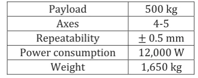
Payload 500 kg

Axes 4-5

Repeatability ± 0.5 mm

Power consumption 12,000 W

[image:42.595.170.365.293.370.2]

Weight 1,650 kg

Table 2 - 8. CP500L specifications. (Kawasaki, 2015, p.9)

Kawasaki’s CP500L is a robust robotic arm developed mainly for palletising applications. With a payload of 500kg, this arm is ideal for heavy lifting and stacking. Safety is a big concern when manipulator arms of this magnitude are involved, hence Kawasaki have developed a ‘Safety function’ which cuts power to the robot in the event of human interaction or motion detection in the ‘Safety fence’ area (Kawasaki, 2015, p.6).

The E03 is required for control of this manipulator arm. ‘K-ROSET’ is the software package used with this system and includes several pre-programming palletising patterns (fig. 2 - 19). The layout of the surrounding environment may also be configured in software, enabling auto collision-avoidance and control. Depending on end-effector, Kawasaki caters to a large range of packing applications.

Figure 2 - 19. Kawasaki palletising patterns. (Kawasaki, 2015).

(43)

2.3 Market Research - Service Robotics

2.3.1 Kinova JACO

Figure 2 - 20. Kinova Jaco picture. (Kinova Robotics, 2009).

Founded in 2006, Kinova Robotics is a Canadian based company specialising in the production and implementation of service and assistive robotics. Their first major release came in 2010, with the launch of JACO, a six degree of freedom (DOF) robotic manipulator arm. Although the JACO arm has shown success in both industrial and assistive applications, it has been heavily marketed to help the wheelchair bound, physically impaired, with the original intended use to enhance the independence of the user.

The manipulator arm comes with a choice of two end-effectors, 2 fingered, or 3 fingered, depending on operation requirements. This product has put great emphasis on the needs of the user, tailoring each unit specifically. This system acts as an add-on, integrating directly with an electric wheelchair and drawing power from the same battery. This introduces unique design challenges, resulting in a light-weight arm, with relatively low power consumption.

Weight 5.2 kg

Payload 1.6 kg

Reach 900 mm

Power consumption 25 W, 5W standby Construction Carbon fiber Linear speed 200 mms-1

Table 2 - 9. Kinova Jaco arm specifications. (Kinova Robotics, 2014, p.4).

While focussing on ‘activities for daily living’, the JACO system is unique in its ability to provide an interface personalised for the user. Control can include, but is not limited to: hand-interfaced joystick, foot-interfaced joystick, mouth actuated (sip and puff), head array (Kinova Robotics, 2015, p.2).

Helping those with (Kinova Robotics, 2015, p.4): Cerebral palsy (CP)

Spinal muscular atrophy (SMA) Spinal cord injury (SCI)

(44)

Intended use covers tasks such as eating, drinking, using a microwave and general household responsibilities which may be difficult for those suffering with compromising disabilities. The arm is generally mounted to the side of a wheelchair seat frame.

Customer Support

[image:44.595.242.296.239.297.2]

Kinova Robotics offers a range of comprehensive support to their customers. It is fairly obvious to note that this should be an integral part of the product, due to the nature of their intended clients. According to the JACO Assistive Robotic Arm e-brochure made available by Kinova Robotics (2015), a free pre-installation home or on-site evaluation is provided on request. This seems to be ideal for opening the initial client-company relations. Because of the tailoring nature of the JACO system, this is also a necessity.

Figure 2 - 21. Kinocare logo. (Kinova Robotics, 2015).

Kinocare ‘BASIC’ is a supporting package included in the purchase of any of Kinova’s service robotic products. The coverage ranges depending on the selected bundle, with ‘PLUS’ and ‘PREMIUM’ upgrades available. Kinocare ‘BASIC’ includes minimum technical support, with a 24-hour contact reply time guaranteed by Kinova. This package also comes with a 2-year limited warranty, which warrants that each new product shall be free from defects in material and workmanship, as well as operate correctly as described by the User Manual for a continuous period of 24 months. This does not include damage caused to the system by the user.

The Kinocare ‘PLUS’ features an extended 3-year limited warranty, with the same terms as prescribed by the ‘BASIC’ package. The 24-hour contact response time is also included. A repair discount of 15% is applied to the invoice of any repairs done by Kinova on the product which includes the Kinocare ‘PLUS’ coverage.

Most extensive, Kinocare ‘PREMIUM’ is the maximum coverage available. The limited warranty is extended by 2 years, providing the user with a total of 4 years of security. The repair discount is increased to 25% and one ‘Complete tune up and maintenance’ contract is added to the package. This includes product inspection and diagnoses, as well as software or hardware updates. Damaged or defective parts are also replaced, not excluding aesthetic faults.

Pricing:

Kinocare ‘BASIC’: Free with product purchase Kinocare ‘PLUS’: $3000

Kinocare ‘Premium’: $7500

(45)

Kinova Jacosoft

[image:45.595.276.374.440.546.2]

Kinova Jacosoft is software designed specifically for use with the JACO or MICO systems. The purpose of this software ranges from general information to diagnosis, depending on the licence type acquired by the user (tab. 2 - 10):

Table 2 - 10. Kinova Jacosoft available packages. (Kinova Robotics, 2015).

Jacosoft allows the user to position the robot in specific configurations, which may be saved, loaded, imported and exported (Kinova Robotics, 2014, p.8). The software also includes angular and Cartesian control methodologies. Once the required trajectory and positional settings have been configured as desired by the user, this information may be exported to the control unit, for quick use. Jacosoft also allows the default ‘Retracted’ position as well as trajectory settings to be altered.

Other settings may also be changed. These include joystick sensitivity, arm linear speed, drinking mode, spasm filter and mapping info. Mapping info allows the controller’s outputs to be customised, depending on input.

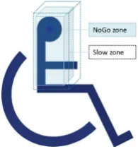
Figure 2 - 22. Jacosoft NoGo and Slow zone diagram. (Kinova Robotics, 2015).

One unique aspect to Jacosoft and the JACO system is the ‘NoGo Zone’ (Kinova Robotics, 2014, p.26). This is a user-defined zone (fig. 2 - 22) which the robot will take into account when executing a movement command. The intention is to provide a safe zone for the operator, which the robotic arm may not enter. There is also a grace zone, slowing robot activity at the border of the ‘Slow Zone’.

The ‘Roboticist Central’ tab in Jacosoft includes options such as ‘Set PID filter’, ‘Set PID’, ‘Set zero position’, ‘Set actuator address’ and ‘Force control’ (Kinova Robotics, 2014, p.32). These options allow for finer control and are recommended for advanced users.

(46)

Actuators

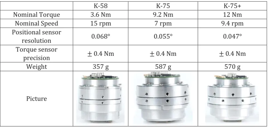
Interestingly, Kinova Robotics have made available some of their internal hardware for purchase. In particular, there is an entire product range devoted to the sales of Kinova actuators (Kinova Robotics, 2014). There are three main models, including: K-58, K-75 and K-75+. The main differences between these models are their size, however the + model provides an increase in other properties relative to the lower models.

Although access to internal workings and electronics are limited, a significant amount of technical specifications are provided.

K-58 K-75 K-75+

Nominal Torque 3.6 Nm 9.2 Nm 12 Nm

Nominal Speed 15 rpm 7 rpm 9.4 rpm

Positional sensor

resolution 0.068° 0.055° 0.047°

Torque sensor

precision ± 0.4 Nm ± 0.4 Nm ± 0.4 Nm

Weight 357 g 587 g 570 g

[image:46.595.51.489.207.414.2]

Picture

Table 2 - 11. Kinova actuator specifications. (Kinova Robotics, 2015).

(47)

Design Aspects

The design constraints imposed by the nature of the product has resulted in a light-weight arm with low power consumption. The way in which Kinova have reduced overall weight is by reducing the total material used. Their design comprises of hollow structures, which provide enough strength for the manipulator arm, while not over-designed significantly. The use of carbon fibre further reduces arm weight. The final weight of the 6 DOF JACO model is 5.4kg, excluding the end-effector (Kinova Robotics, 2014, p.4).

[image:47.595.231.426.632.742.2]

Power usage is a priority. The unique actuators manufactured by Kinova do not incorporate the use of stepper motors. Instead brushless DC motors are used in conjunction with the Kinovo ratio 136 Harmonic Drive. It is unclear due to lack of information, but this may influence power consumption.

Figure 2 - 23. 6 DOF JACO dimensions. (Kinova Robotics, 2015).

The 6-DOF manipulator arm has several actuated joints (fig 2 - 23). A rotating joint is used at the base of the robot, allowing movement for majority of the arm. Two additional joints are used, separated significantly to improve working space. Interestingly, to allow for finer end-effector control, two joints are used, each offset by 60° relative to arm 2. A final rotating actuator is used at the base of the end-effector. It should be noted that all joints required for actuation of the JACO manipulator arm are rotationally actuated. This design permits robot interaction at floor level, enabling the user to work with objects on the floor.

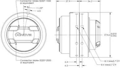
JACO includes a somewhat modular design. Each arm segment is separate from one another, with actuation devices not integrated with the arm. Actuators are attached to the arm through the use of 8 fastening screws (fig 2 - 24). This simplifies the system significantly and allows for relatively uncomplicated repairs. This does mean however that all parts must be manufactured to a certain precision, as to avoid misalignment.

(48)

End-effector grippers are under actuated and include temperature sensors, as well as rotational encoders. With an opening range of 175mm and a gripping force of 40N (Kinova Robotics, 2015, p.2), the 3-fingered grippers are able to accommodate majority of tasks. The gripper includes rounded contact surfaces for better grip as this increases the effective friction area. A plastic insert at the centre of the gripper increases its ability to handle circular objects.

(49)
[image:49.595.248.405.99.232.2]

2.3.2 Bestic

Figure 2 - 26. Bestic picture. (Bestic AB, 2015).

Bestic AB specialises in assistive eating devices. Founded in 2004, the Swedish company developed Bestic over seven years with the help from Swedish organisations and sectors such as the Swedish Institute of Assistive Technology, Robotdalen and Promobilia. The company has spread to include customers in Denmark, Finland, Noway, Holland, English, Spain, France and the USA.

Launched is 2011, Bestic is a simple manipulator arm, designed solely for aiding those who may have trouble eating from diminished arm or hand functionality. The ‘one button - one press - one bite’ interface allows the user to control the arm with comfort. Noting that this manipulator is also battery operated and fits inside a Bestic backpack, enabling the user to eat on their own terms and on their own time. The system includes the Bestic manipulator arm, a spoon end-effector attachment and the application specific plate. The utensils provided by Bestic are dishwasher friendly.

This 4 DOF robot is controllable through either a simple one-button interface or the more advanced five-button Picasso MINI controller. The one-button interface is adapted to the user, depending on individual requirements. Although the five-button control device allows for functionality, it may not always be suited for the user.

Bestic is a robust robot from necessity and consequently makes use of this to include several features. It is recommended that the user handle the robotic arm at the lower end of the middle link. The arm is also water-resistant.

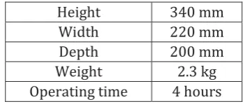
Height 340 mm

Width 220 mm

Depth 200 mm

Weight 2.3 kg

Operating time 4 hours

Table 2 - 12. Bestic specifications. (Bestic AB, 2015).

[image:49.595.237.413.579.654.2]
(50)
[image:50.595.186.353.106.248.2] [image:50.595.185.359.650.740.2]

Design Aspects

Figure 2 - 27. Bestic diagram. (Bestic AB, 2015).

As a result of the unique design constraints enforced on the Bestic manipulator arm by its target audience, the end-effector design is required to be simplistic and easily detachable (Bestic AB, 2015, p.13). The spoon attachment incorporates the use of a living hinge and slot configuration (fig. 2 - 27).

Through the use of elastic deformation, the spoon attachment is able to bend around the outer limits of its allotted slots to snap into position (fig. 2 - 28). The deformation is reversible and does not permanently damage the attachment. Inside the homing slot, there is a smaller slit (fig. 2 - 28) which provides rotational actuation to the end-effector.

Figure 2 - 28. Bestic spoon attachment diagram. (Bestic AB, 2015).

In an effort to reduce complexity of the system, Bestic have provided their own specific plate. This has been done to both standardise the system and provide a consistent operating environment for the robotic manipulator arm. Bestic’s circular base design enables positional control of the plate, once the plate has been pushed up against the base (fig. 2 - 29), its position will always be constant. This allows for pre-programed positions and command chains to be established. A non-stick mat is included.

(51)
[image:51.595.248.404.584.694.2]

Bestic supports and provides two main types of control devices (Bestic AB, 2015, p.20). The one-button interface (fig. 2 - 30) is essentially one large button which provides a single one-step command to the arm. Each press of this button corresponds to one eating cycle. The arm will swing down, allowing the end-effector to gather food, the food will then be transported upward to the user for consumption after a scrape cycle. The scrape cycle brushes the spoon end-effector past the brim of the plate, as to remove any debris from the bottom of the attachment before passing it along to the user. Prior to the scrape cycle, the spoon is gently swayed from side to side, eliminating any food which would tend to fall off mid transference.

Figure 2 - 30. Bestic Picasso MINI. (Bestic AB, 2015).

Bestic also offers a more advanced control device, the Bestic Picasso MINI (fig. 2 - 30). This is a USB operated pad, with five unique control buttons. The robotic arm may be manipulated in a Cartesian-like fashion, with the middle button changing which cycle the arm is in. In the case of the Picasso MINI, the arm has several more cycles than the one-button operation and may be set-up depending on user preference. The default setting allows XY movement of the end effector, once the middle button is pressed, the scrape and feed function and executed.

Bestic includes a limited display (fig. 2 - 31). This provides the user with the state of the battery power and several other unique pieces of information. This is also how the menu is accessed. The menu is navigated through the use of the Picasso MINI controller. Individual profiles are included in the settings, enabling the user to configure end-effector feeding height and XY position. Control options are also changeable, which sees the user pick the 1-click or 2-click option. The 1-click option runs through the entire scrape-feed cycle, while the 2-click option splits this into two.

Figure 2 - 31. Bestic control display diagram. (Bestic AB, 2015).

(52)

Figure

Figure 1 - 1. London jobs at risk of computerisation. (Kowles-Cutler, et al., 2014). Copyright 2014 by Deloitte
Figure 2 - 1. Scorbot-ER 9Pro picture. (Intelitek, 2008).
Figure 2 - 8. Typical velocity curves. (Intelitek, 2008).
Figure 2 - 13. Harmonic drive exploded view. (Intelitek, 2008).
+7

References

Related documents

It was decided that with the presence of such significant red flag signs that she should undergo advanced imaging, in this case an MRI, that revealed an underlying malignancy, which

The objective is to investigate whether enriched enteral nutrition given shortly before, during and early after colo- rectal surgery, reduces POI and AL via stimulation of the

The use of sodium polyacrylate in concrete as a super absorbent polymer has promising potential to increase numerous concrete properties, including concrete

19% serve a county. Fourteen per cent of the centers provide service for adjoining states in addition to the states in which they are located; usually these adjoining states have

Хат уу буудай нъ ТгШсит ёигит зүйлд хамаарагддаг нэг настай ихэечлэн зусах хэлбэртэй үет ургамал бөгөөд уураг ихтэй, шилэрхэг үртэй, натур жин их байдгаараа

A perceived way out of the administrative challenge was to transform university knowledge production in order to create jobs, ensure equitable income distribution, improve

The nutritive value in vitro organic matter digestibility, neutral detergent fibre and nitrogen content of Aries HD was similar to that of Yatsyn 1 perennial ryegrass, from

2 Equity Market Contagion during the Global Financial Crisis: Evidence from the World’s Eight Largest Economies 10..