A DEVELOPMENT OF MODULAR AUTOMATED STORAGE AND
RETRIEVAL SYSTEM
This report is submitted in accordance with the requirements of Universiti Teknikal Malaysia Melaka (UTeM) for the Bachelor’s Degree of Manufacturing Engineering
(Robotics and Automation)(Hons.)
by
LEOW ZHI LI B051310117 930804-10-5539
Disahkan oleh:
_____________________________ ______________________________ Alamat Tetap: Cop Rasmi:
1A-10-02, Desa Delima, Lorong Semarak Api 2, Bandar Baru Air Itam, Air Itam,
11500 Pulau Pinang
Tarikh: 17/06/2017 Tarikh: _______________________ *Jika Laporan PSM ini SULIT atau TERHAD, sila lampirkan surat daripada pihak berkuasa/organisasi berkenaan dengan menyatakan sekali sebab dan tempoh laporan PSM ini perlu dikelaskan sebagai SULIT atau TERHAD.
UNIVERSITI TEKNIKAL MALAYSIA
BORANG PENGESAHAN STATUS LAPORAN PROJEK SARJANA MUDA
Tajuk: A DEVELOPMENT OF MODULAR AUTOMATED STORAGE AND
RETRIEVAL SYSTEM
Sesi Pengajian: 2016/2017 Semester 2
Saya LEOW ZHI LI (930804-10-5539)
mengaku membenarkan Laporan Projek Sarjana Muda (PSM) ini disimpan di Perpustakaan Universiti Teknikal Malaysia Melaka (UTeM) dengan syarat-syarat kegunaan seperti berikut:
1. Laporan PSM adalah hak milik Universiti Teknikal Malaysia Melaka dan penulis. 2. Perpustakaan Universiti Teknikal Malaysia Melaka dibenarkan membuat salinan
untuk tujuan pengajian sahaja dengan izin penulis.
3. Perpustakaan dibenarkan membuat salinan laporan PSM ini sebagai bahan pertukaran antara institusi pengajian tinggi.
4. *Sila tandakan (√)
(Mengandungi maklumat yang berdarjah keselamatan atau kepentingan Malaysiasebagaimana yang termaktub dalam AKTA RAHSIA RASMI 1972)
(Mengandungi maklumat TERHAD yang telah ditentukan oleh organisasi/ badan di mana penyelidikan dijalankan)
SULIT
TERHAD
DECLARATION
I hereby declare that this report, entitled “A Development of Modular Automated Storage
and Retrieval System”, is the result of my own research except as cited in references.
Signature : ………
Author’s Name : LEOW ZHI LI
APPROVAL
This report is submitted to the Faculty of Manufacturing Engineering of Universiti
Teknikal Malaysia Melaka as a partial fulfillment of the requirements for Degree of
Manufacturing Engineering (Robotics and Automation) (Hons.). The members of the
supervisory committee are as follows:
………...
ABSTRAK
Laporan ini mendokumentasikan perjalanan projek bertajuk “Pembangunan Sistem
Automasi bagi Penyimpanan dan Dapatan Semula yang Berkonsep Modular”. Dalam
projek ini, sebuah AS/RS modular dicadangkan untuk menangani masalah AS/RS yang
dipasang tetap dan tidak mudah diubah secara fizikal. Objektif projek ini adalah mereka
bentuk sebuah AS/RS modular yang senang dipasang dan ditanggalkan, menghasilkan
AS/RS yang telah direka bentuk, dan mensimulasikan kawalan sistem tersebut. AS/RS ini
direka bentuk sebagai komponen individu dengan menggunakan SolidWorks. Kemudian,
perisian yang sama digunakan untuk menghimpunkan komponen menjadi suatu reka
bentuk yang lengkap. Apabila mereka bentuk sistem, pelbagai konsep reka bentuk
dinilaikan dan dibandingkan demi memilih konsep yang terbaik untuk reka bentuk sistem.
Sejurusnya, aspek-aspek rekabentuk dan modular reka bentuk akhir dibincangkan dan
dibandingkan dengan AS/RS bukan modular. Melalui perbandingan setiap bahagian, sifat
modular sistem yang telah direka bentuk dibuktikan. AS/RS yang telah direkabentuk juga
dibina sebagai sebuah produk fizikal dengan aluminium sebagai bahan utamanya. Akhir
sekali, simulasi kawalan sistem menggunakan perisian Automation Studio dibentangkan
dan dibincangkan. Sebuah panel kawalan maya, grid maya, dan perwakilan sistem
dibentangkan. Pengaturcaraan logik di sebalik kawalan sistem juga dibentangkan dan
dijelaskan. Dengan pengaturcaraan yang disediakan, sistem tersebut mampu bergerak ke
mana-mana kedudukan pada grid, serta mengambil dan meletakkan barang dari grid. Logik
ABSTRACT
This report documents the progress of the project “A Development of Modular
Automated Storage and Retrieval System”. In this project, a modular AS/RS is proposed in
order to counter the problem of AS/RS being permanent fixtures and unwelcoming to
physical changes. The objectives of the project are to design a modular AS/RS that is easy
to install and remove, fabricate the designed AS/RS, and simulate control of the system.
The AS/RS is designed as individual parts in SolidWorks. Later on, the same program is
used to assemble the parts into the complete design. When designing the system, various
design concepts are proposed, evaluated, and compared in order to select the best concepts
for the design of the system. The various design and modular aspects of the final design are
then discussed and compared with non-modular AS/RSs. Through a section-by-section
comparison, the modularity of the system that has been designed is proven. The designed
AS/RS is also fabricated in the form of a physical product, with its main material being
aluminium. Finally, the simulation of the system’s control in Automaton Studio is
presented and discussed. The virtual control panel to control system, virtual grid, and
representation of the system are presented. The ladder logic programming behind the
control of the system is also presented and explained. With the ladder programs in place,
the system is able to move to any position on the virtual grid, as well as store and retrieve
virtual items from the grid. The logic used in the control of the system is also expandable
DEDICATION
This project is dedicated to my parents. To my mother, for her unending support
throughout my time studying here in UTeM. And to my father, who could not be here to
ACKNOWLEDGEMENT
A thousand and one thanks go out to all the people that have contributed to the
completion of this project.
The first and biggest “thank you” goes to my supervisor, Dr.-Ing Azrul Azwan. His
guidance and advice helped me to undertake this project in the best way I could. I would
also like to thank him for his tolerance towards my many shortcomings.
The assistant engineers, Mr. Azwan and Mr. Mazlan are not to be forgotten.
Without their help, the completion of this project would have been impossible.
My friends and course-mates also deserve my gratitude. Some helped me by giving
me support, advice, and opinions. Others even went as far as to help me with a bit of the
physical work of my project, even when they had their own work to do.
Finally, I would like to thank my family, for all their support throughout the
TABLE OF CONTENTS
Abstrak... i
Abstract ... ii
Dedication ... iii
Acknowledgement ... iv
Table of Contents... v
List of Tables ... viii
List of Figures ... x
List of Abbreviations ... xii
List of Symbols ... xiii
CHAPTER 1: INTRODUCTION ... 1
1.0 Background of Study ... 1
1.1 Problem Statement ... 2
1.2 Objectives ... 3
1.3 Scope ... 3
CHAPTER 2: LITERATURE REVIEW ... 4
2.0 Overview for AS/RS ... 4
2.1 Automation in Industries ... 9
2.1.1 Automated Material Handling ... 11
2.2 Design Considerations ... 13
2.2.1 Basic Elements of AS/RS Design ... 15
2.2.2 Calculation of Storage Space Dimensions ... 17
2.2.3 Estimation of Aisle and System Dimensions ... 19
2.3 Mechanism for Robot Movement ... 20
2.3.1 Rack and Pinion Drive ... 20
2.3.2 Ball and Screw Drive ... 21
2.3.3 Stewart-Gough Platform ... 22
2.4 Control Systems ... 23
2.5 Modularity ... 29
CHAPTER 3: METHODOLOGY ... 30
3.0 Overall Development Process ... 30
3.1 Software Tools ... 33
3.1.1 SolidWorks 2013 ... 33
3.1.2 Automation Studio 6 ... 33
3.2 Hardware ... 34
3.3 Design Concept Generation ... 35
3.3.1 Axis Mounting Arrangement ... 36
3.3.2 Joint between Axes ... 38
3.3.3 Storage Rack Attachment ... 41
3.4 Simulation of Control ... 44
CHAPTER 4: RESULTS AND DISCUSSION ... 45
4.0 Design Selection ... 45
4.1 Final Design ... 47
4.1.1 Materials Used ... 50
4.1.2 Individual Parts ... 50
4.2 Assembled Sections and Modularity ... 55
4.2.1 X-Axis ... 55
4.2.2 Y-Axis ... 57
4.2.3 Rack Mounting Mechanism (Bottom) ... 59
4.2.4 Rack Mounting Mechanism (Top) ... 60
4.2.5 Joint between Axes ... 62
4.3 Fabricated Product ... 63
4.4 Simulation of System Control ... 68
4.4.1 System Representation ... 70
4.4.2 Connections To and From PLC ... 71
4.4.3 Ladder Programming ... 73
4.4.4 Outcome of Simulation ... 85
CHAPTER 5: CONCLUSION AND RECOMMENDATION ... 87
5.0 Conclusion ... 87
5.1 Recommendation for Future Work ... 88
REFERENCES ... 89
APPENDICES ... 93
Appendix A Technical Drawings Used for Milling ... 94
LIST OF TABLES
3.1 Objects used in design generation illustrations 35
3.2 Design concepts for mounting arrangements 36
3.3 Evaluation table for axis arrangement 38
3.4 Design concept for joint between axes (A) 39
3.5 Design concept for joint between axes (B) 39
3.6 Design concept for joint between axes (C) 40
3.7 Evaluation table for joint between axes 40
3.8 Design concept for adjustable rails (A) 41
3.9 Design concept for adjustable rails (B) 42
3.10 Design concept for adjustable rails (C) 42
3.11 Evaluation table for adjustable rail 43
4.1 Evaluation results for mounting arrangement 45
4.2 Evaluation results for joint between axes 46
4.3 Evaluation table for adjustable rail 46
4.4 Left, front, and right views of final design of the AS/RS 48
4.5 Back, top and bottom views of final design of the AS/RS 48
4.6 Description for aluminium profile bar 50
4.7 Description for rail end piece 51
4.8 Description for x-axis mounting piece (A) 51
4.9 Description for x-axis mounting piece (B) 51
4.10 Description for inter-axis mounting piece (A) 52
4.11 Description for inter-axis mounting piece (B) 52
4.12 Description for y-axis mounting piece and slider 53
4.13 Description for rail locking plate 53
4.14 Description for motor mounting piece 54
4.16 Description for x-axis end piece 55
4.17 List of connections to and from PLC 72
4.18 Truth table for movement direction of x-axis 82
LIST OF FIGURES
2.1 Typical layout of an AS/RS system (Ku et al., 2015) 5
2.2 Illustration of AS/RS system 6
2.3 Timeline of advancements in automation technology 9
2.4 Basic structure of an automation system (Sharma, 2016b) 10
2.5 Flexible suction gripper (Hamberg, 2011) 12
2.6 Operating principle of rack and pinion railway 20
2.7 Ball and screw drive with cutaway view at nut (Altintas et al., 2011) 21
2.8 Prototype of Stewart-Gough Platform based AS/RS (Salah et al., 2015) 23
2.9 Figure 2.9: Block diagram for open-loop system 24
2.10 Block diagram of closed-loop system. 24
2.11 Omron CP1H Programmable Logic Controller (Omron, 2016) 25
2.12 Arrangement of components in a PLC (Bolton, 2015a) 26
2.13 Part of a ladder diagram (PLCAcademy, 2016) 27
3.1 Development process during FYP1 30
3.2 Development process during FPY2 32
3.3 Control panel and system representation 44
4.1 Completed final design of the AS/RS 47
4.2 Top area of final design of the AS/RS 49
4.3 Bottom area of final design of the AS/RS 49
4.4 X-Axis of the AS/RS 56
4.5 Y-Axis of the AS/RS 57
4.6 Rack mounting mechanism (bottom) 59
4.7 Rack mounting mechanism (top) 61
4.8 Joint between x and y-axes 63
4.9 Front view of completed product 64
4.10 Top mounted adjustable rail of the product 65
[image:14.595.88.523.135.760.2]4.12 X-Axis attached to bottom rack mounting mechanism 66
4.13 Joint between x-axis and y-axis 66
4.14 Y-Axis of fabricated product 67
4.15 Virtual control panel for system control 69
4.16 Virtual grid for system 69
4.17 Representation of physical system 70
4.18 Ladder diagram for power control 73
4.19 Ladder diagram for storage process 74
4.20 Logic flowchart for storage process 75
4.21 Ladder diagram for retrieval process 77
4.22 Logic flowchart for retrieval process 78
4.23 Ladder diagram for control of x-axis 80
4.24 Logic flowchart for control of x-axis 81
4.25 Ladder diagram for control of y-axis 82
LIST OF ABBREVIATIONS
AS/RS - Automated Storage and Retrieval System
CAD - Computer Aided Design
CAE - Computer Aided Engineering
CNC - Computer Numerically Controlled
DCV - Directional Control Valve
ERP - Enterprise Resource Planning
FOSH - Free and Open-Source Hardware
FOSS - Free and Open-source Software
FYP1 - Final Year Project 1
FYP2 - Final Year Project 2
N/O - Normally Open
PC - Personal Computer
PLC - Programmable Logic Controller
RGV - Rail-Guided Vehicle
RPD - Rack and Pinion Drive
UML - Unified Modeling Language
LIST OF SYMBOLS
- Aisle unit
ௐ - Aisle width
- Capacity per aisle
ெ - Capacity of each storage/retrieval machine
- Length of storage rack
- Width of storage rack
- Height of storage rack
ௌ - Overall length of system
ௌ - Overall width of system
ௌ - Overall height of system
l - Length of load
b - Width of load
h - Height of load
x - Length clearance of load
y - Width clearance of load
z - Height clearance of load
ௌௌ - Length of storage space
ௌௌ - Width of storage space
ௌௌ - Height of storage space
- Length of storage compartment
ௌௌ - Length of storage space
ଵ - Thickness of support column
- Width of storage compartment
ଵ - Thickness of support column
- Height of storage compartment
ଵ - Storage rack centre-to-centre height
ௌோ/ெ - Number of storage racks per storage/retrieval machine
ெ - Number of storage/retrieval machines
ௌோ - Number of storage spaces per storage rack
- Number of aisles
ௌ - Total number of rows
ௌ - Total number of bays
ோ - Number of rows
- Number of bays
ɳhr - Approximate hourly throughput of the system
ௌௌ - Number of storage spaces required in the system
ௌ - Single command cycle time
- Dual command cycle time
ௌ(ெ) - Maximum single command cycle time
(ெ) - Maximum dual command cycle time
ɳ/ௌ - Hourly throughput based on single command cycle
CHAPTER 1
INTRODUCTION
1.0 Background of Study
Automated storage and retrieval systems (AS/RS) (MHI, 2012) are systems that
automatically place and retrieve loads from pre-defined storage locations. These systems
are generally computer-controlled. AS/RS systems are prized for their high rate of storage
and retrieval. The installation of these systems also allows for higher storage density in
warehouses and other storage locations compared to traditional storage layouts that employ
forklift trucks for storage and retrieval.
Originating in the 1960s, the technology evolved from its initial focus on heavier
pallet loads to become smaller and more compact (Rogers, 2012). As a result, there exists a
wide variety of AS/RS systems that cater for anything from pallet loads weighing a few
tonnes to mini AS/RS systems that can be efficiently and effectively used to store and
retrieve small loads.
In an article by Stephen (2012), it is mentioned that AS/RS systems allows for
simpler tracking of stocked products. This includes their respective suppliers, the time and
duration they were stored, as well as their locations. The author went on to elaborate that
such information allows for better planning and management of warehouse space.
There are two main types of AS/RS systems: Vertical lift module (VLM) and
horizontal carousels. VLM type AS/RS systems store items in vertical racks. The storage
and retrieval system is able to move on a horizontal or vertical (usually both) axis to store
and retrieve products from individual rack spaces.
Horizontal carousel type AS/RS systems, on the other hand, feature a series of bins
retrieval, usually done by human workers, is done by inputting the desired location. The
track will then rotate to present the appointed bin to the user.
A different approach of categorizing AS/RSs is single command cycle or dual
command cycles. Single command cycle type AS/RS only handles the storage or retrieval
of one item in one command cycle. On the other hand, dual command cycle AS/RSs can
handle more than one storage and/or retrieval command per command cycle.
AS/RS systems, since their creation, have helped to improve the effectiveness and
efficiency of storage and retrieval work in warehouses. Of course, the uses for such a
system are not limited to industrial sectors only. In the future, these systems are sure to
play an even larger role as industries worldwide continuously strive for a more automated
workforce.
1.1 Problem Statement
Traditional AS/RS systems are usually considerably large in size, due to their major
use case being factory warehouses and storage areas. As a result of this, and the fact that
they usually include complex interfaces with other systems, AS/RS systems tend to be
difficult to install and remove. AS/RS systems are also usually made to order. This causes
the system to not accept physical changes easily. For example, if a client wishes to replace
the current storage rack with a new one of different dimensions, many components of the
ASRS may need to be replaced as well.
To overcome this, a modular AS/RS is proposed. The system should be adaptable
(within a reasonable range) to changes in the dimensions of the storage rack. Such a system
would also minimize the need to custom-make components for different clients. The
1.2 Objectives
Throughout the course of this project, there are 3 main objectives that need to be met.
1. To design a modular AS/RS system that is simple to install and remove from the
storage racks.
2. To fabricate the AS/RS system that has been designed.
3. To simulate the control of the AS/RS.
1.3 Scope
In Section 1.0, it was mentioned that there are two main types of AS/RS systems,
VLM type and horizontal carousel. In this project, only the VLM type of AS/RS systems
will be approached. This is due to the vastly different form factors of the two types of
AS/RS, which does not allow for both types to be incorporated into the same system
effectively.
The work for this project will include designing a single command cycle AS/RS
using computer aided design. The designed system will also be fabricated and assembled.
CHAPTER 2
LITERATURE REVIEW
2.0 Overview for AS/RS
Ku et al. (2016) discussed the possibilities of developing software for the control
and monitoring of AS/RS systems. The authors described automated storage systems as a
vital part of logistics. Due to the current trends in consumer lifestyles, large quantities of
goods are required for a short time. To this effect, AS/RS systems contribute immensely in
conserving human capital and present higher reliability.
In Slovakia, there is a large demand for new modelling and control methods for
AS/RS systems, especially in the automotive industry. However, the purchase and
installation of these systems are costly, excluding the development of suitable software that
is required for the functioning of the systems.
According to Ku et al. (2016), AS/RS systems usually consist of racks, aisles,
cranes, input and output points, and interoperable transport. First, they describe racks as
“mostly metal structures where pallets with items are placed.” In other words, racks are
where the products are stored in an AS/RS system. Naturally, racks usually represent most
of the volume of any AS/RS system.
Aisles are the empty spaces between racks. Aisles tend to have two main purposes.
The first is to allow human workers to walk between the racks. This can be for doing stock
checks, or repairs and maintenance of the AS/RS system. The second purpose is for the
movement of the cranes (Ku et al., 2016). As the cranes do not sit flush with the racks,
they require space to move around and pick or place pallets from the storage racks.
Cranes, as mentioned in the paragraph above, are fully automated devices that store
be based on a variety of platforms, including rack and pinion, ball and screw, Stewart-Gough Platform, etc. Each different platform of crane has its own benefits and drawbacks to be considered.
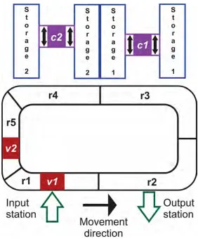
The last part of AS/RS systems mentioned by Ku et al. (2016) interoperable transport, is sometimes not a part of the AS/RS system itself. However, it remains an essential part of automated storage systems. Interoperable transports are the part of the system that provides transportation of items from the storage area to other parts of the company or plant (and vice versa). One example of such a part provided by the authors are rail-guided vehicles (RGV). Figure 2.1, shows an illustration of a typical layout of an AS/RS system.
[image:23.595.163.445.313.653.2]
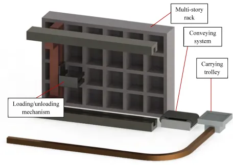
Guanxiang et al. (2010) described AS/RS systems as an evolved form of warehouses. Figure 2.2 shows an illustration that includes some of the parts of an AS/RS as described by the authors.
Figure 2.2: Illustration of AS/RS system
Other parts of AS/RS as listed by Guanxiang et al. (2010) that are not shown in Figure 2.2 include the following:
1. Tunnel type stackers
2. Container or pallet facilities 3. Communication systems 4. Information systems 5. Control systems
6. Computer management and monitoring system
Multi-story rack
Loading/unloading
mechanism
Conveying
system