UNIVERSITI TEKNIKAL MALAYSIA MELAKA
BLADE-GENERATOR STRUCTURE ANALYSIS AND
TOPOLOGY OPTIMIZATION OF SAVONIUS VERTICAL AXIS
WIND TURBINE
This report is submitted in accordance with the requirement of the Universiti Teknikal Malaysia Melaka (UTeM) for the Bachelor of Mechanical Engineering
Technology (Maintenance Technology) with Honours.
by
LUAH CHII HAO B071410292 940928-01-6721
UNIVERSITI TEKNIKAL MALAYSIA MELAKA
BORANG PENGESAHAN STATUS LAPORAN PROJEK SARJANA MUDA
TAJUK: BLADE-GENERATOR STRUCTURE ANALYSIS AND TOPOLOGY OPTIMIZATION OF SAVONIUS VERTICAL AXIS WIND TURBINE
SESI PENGAJIAN: 2017/18 Semester 1
Saya LUAH CHII HAO
mengaku membenarkan Laporan PSM ini disimpan di Perpustakaan Universiti Teknikal Malaysia Melaka (UTeM) dengan syarat-syarat kegunaan seperti berikut:
1. Laporan PSM adalah hak milik Universiti Teknikal Malaysia Melaka dan penulis. 2. Perpustakaan Universiti Teknikal Malaysia Melaka dibenarkan membuat salinan
untuk tujuan pengajian sahaja dengan izin penulis.
3. Perpustakaan dibenarkan membuat salinan laporan PSM ini sebagai bahan pertukaran antara institusi pengajian tinggi.
4. **Silatandakan ( )
SULIT
(Mengandungi maklumat yang berdarjah keselamatan atau kepentingan Malaysia sebagaimana yang termaktub dalam AKTA RAHSIA RASMI 1972)
TERHAD
(Mengandungi maklumat TERHAD yang telah
ditentukan oleh organisasi/badan di mana penyelidikan dijalankan)
TIDAK TERHAD
Disahkan oleh:
Alamat Tetap:
NO. 5, JALAN HAJI DAHLAN DIKON, Cop Rasmi:
KLUANG BARU, 86000
KLUANG, JOHOR.
Tarikh: Tarikh:
DECLARATION
I hereby, declared this report entitled “Blade-Generator Structure Analysis and Topology Optimization of Savonius Vertical Axis Wind Turbine” is the results of my
own research except as cited in references.
Signature : ………
Author’s Name : ………
Date : ………
APPROVAL
This report is submitted to the Faculty of Engineering Technology of UTeM as a partial fulfillment of the requirements for the degree of Bachelor of Mechanical Engineering Technology (Maintenance Technology) with Honours. The member of the supervisory is as follow:
i
ABSTRAK
Era menggunakan tenaga angin untuk mengeluarkan tenaga elektrik telah bermula sejak lewat tahun 1800-an. Turbin angin adalah satu mekanisme yang digunakan untuk menukar tenaga kinetik angin kepada tenaga mekanikal melalui bilah turbin dan kemudian menukar tenaga mekanikal rotor ke tenaga elektrik melului penjana. Walaubagaimanapun, penjana yang sedia ada memerlukan tork yang tinggi untuk memulakan putaran, oleh itu kelajuan angin yang lebih tinggi diperlukan untuk memulakan putaran. Projek ini dijalankan untuk menganalisis pengedaran tekanan ke atas bilah turbin angin jenis Savonius yang direka apabila tenaga angin digunakan pada bilah. Reka bentuk bilah Savonius dihasilkan melalui rumah kualiti dan carta morfologi. 5 reka bentuk telah dipilih dan dibandingkan dengan kaedah Pugh untuk menentukan reka bentuk paling sesuai dalam kajian ini. Selepas reka bentuk dipilih, reka bentuk turbin angin dikaji dengan menggunakkan pengagihan kuasa yang berlainan di permukaan bilah. Analisa dilakukan dengan menggunakan Inspire 2017 yang mana pemutar dipasang pada posisi menggunakan sokongan dan analisa bermula setelah bahan-bahan dipilih. Pengedaran tegasan ke atas bilah
disebabkan daya yang dikenakan akan diperolehi. Keputusan menunjukkan bahawa
ii
ABSTRACT
iii
DEDICATIONS
To my beloved parents and family, my supervisor,
iv
ACKNOWLEDGEMENT
v
TABLE OF CONTENT
Abstrak i
Abstract ii
Dedication iii
Acknowledgement iv
Table of Content v
List of Tables ix
List of Figures x
List of Abbreviations, Symbols and Nomenclatures xii
CHAPTER 1: INTRODUCTION 1
1.1 Background of Study 1
1.2 Problem Statement 4
1.3 Objectives 4
1.4 Scope 5
CHAPTER 2: LITERATURE REVIEW 6
vi
2.1.2.1 Savonius Type VAWT 8 2.1.2.2 Darrieus Type VAWT 9 2.1.2.3 Giromill Type VAWT 10
2.1.3 Operation of a Wind Turbine 11
2.2 Engineering Design 12
2.2.1 House of Quality 12 2.2.2 Morphological Chart 14 2.2.3 Conceptual Design 15 2.3 Material Selection by Ashby Method 15 2.3.1 Magnesium Alloys 16 2.3.2 Aluminium Alloys 17 2.3.3 Polycarbonate 17 2.3.4 Carbon Fiber Reinforced Polymer 18 2.3.5 Glass Fiber Reinforced Polymer 18 2.3.6 Polypropylene 18 2.3.7 Polyethylene 19 2.3.8 Comparison of Materials 19
2.4 Pugh Method 20
2.5 Topology Optimization 21
vii
2.5.2.2 MSC/NASTRAN 22 2.5.2.3 ANSYS DESIGNXPLORE 22 2.5.2.4 GENESIS 23 2.5.2.5 OPTISTRUCT 23 2.5.2.6 TOSCA STRUCTURE 24 2.5.2.7 LS-OPT 24
CHAPTER 3: METHODOLOGY 25
3.1 Introduction 25
3.2 Research Flow 25
3.3 Design Stages of Wind Turbine 27 3.3.1 House of Quality 27 3.3.2 Morphological Chart 30 3.3.3 Pugh Method 30 3.3.4 Conceptual Design 31
3.4 Design Optimization 32
CHAPTER 4: RESULT & DISCUSSION 34
4.1 House of Quality 34
4.2 Morphological Chart 36
4.3 Pugh Method 55
viii
4.5 Parametric Design 58
4.6 Design Optimization 60
CHAPTER 5: CONCLUSION & FUTURE WORKS 73
5.1 Conclusion 73
5.2 Future Works 74
ix
LIST OF TABLES
2.1 Comparison of Materials 19
3.1 Morphological Chart for Savonius Type Wind Turbine 30
3.2 Decision Matrix of Pugh Method 31
4.1 Morphological Chart of Savonius Type Wind Turbine 36
4.2 Concepts from Morphological Chart 38
4.3 Decision Matrix of Pugh Method 55
4.4 Maximum Displacement, Maximum Tension / Compression Stress, 62 Maximum Shear Stress, Maximum Von Mises Stress, Maximum Major Principal Stress, and Factor of Safety for Corresponding Force Applied.
x
LIST OF FIGURES
1.1 Savonius Type VAWT 2
1.2 Darrieus Type VAWT 3
1.3 Giromill Type VAWT 3
2.1 Enercon E-126 7
2.2 Repower M5 7
2.3 Use of Savonius Type VAWT as A Starter in Darrieus Type VAWT 9
2.4 Éole 10
2.5 Giromill Type VAWT 11
2.6 General Components of Wind Turbine 12 2.7 Function of Rooms in House of Quality 13 2.8 Ways to Construct a Morphological Chart 14 2.9 Relationship between Strength and Density of Materials 16 2.10 Decision Matrix Used in Pugh Method. 20
3.1 Flow Chart of Research 26
3.2 House of Quality of Wind Turbine 28
xi
4.2 Conceptual Design of Savonius Type Wind Turbine 58 4.3 3D View of Savonius Type Wind Turbine 59 4.4 Top View of Savonius Type Wind Turbine 59 4.5 Front View of Savonius Type Wind Turbine 60 4.6 Wind Force Applied to Edge of Blade 61 4.7 Wind Forces Uniformly Applied throughout the Surface of Blade 61 4.8 Graph of Force versus Displacement 64 4.9 Graph of Pressure versus Displacement 64 4.10 Graph of Force versus Maximum Tension/Compression Stress 65 4.11 Graph of Pressure versus Maximum Tension/Compression Stress 65 4.12 Graph of Force versus Maximum Shear Stress 66 4.13 Graph of Pressure versus Maximum Shear Stress 66 4.14 Graph of Force versus Maximum Von Mises Stress 67 4.15 Graph of Pressure versus Maximum Von Mises Stress 67 4.16 Graph of Force versus Maximum Major Principal Stress 68 4.17 Graph of Pressure versus Maximum Major Principal Stress 68 4.18 Tension and Compression Stress Distribution at the Front of the Blade 69 4.19 Tension and Compression Stress Distribution at the Behind of the Blade 70 4.20 Maximum Shear Stress, Von Mises Stress, and Major Principal Stress 71
Distribution at the Front of the Blade
4.21 Maximum Shear Stress, Von Mises Stress, and Major Principal Stress 71 Distribution at the Front of the Blade
xii
LIST OF ABBREVIATIONS, SYMBOLS, AND
NOMENCLATURE
ABET - Accreditation Board for Engineering and Technology ATOM - Abaqus Topology Optimization Module
CFRP - Carbon Fiber Reinforced Polymer FEA - Finite Element Analysis
GFRP - Glass Fiber Reinforced Polymer GPa - Giga Pascal
- Grams per cubic centimeter HAWT - Horizontal Axis Wind Turbine - Kilograms per cubic meter m - Meter
- Square meter MPa - Mega Pascal MW - Mega Watt m/s - Meters per second N - Newton
NURBS - Non-Uniform Rational Basis Spline NVH - Noise-Vibration-Harshness
xiii
PC - Polycarbonate PE - Polyethylene PP - Polypropylene
1
CHAPTER 1
INTRODUCTION
1.1 BACKGROUND OF STUDY
2
tower. However, a VAWT has a vertical rotor shaft which different from HAWT and its rotor and components are located at the bottom.
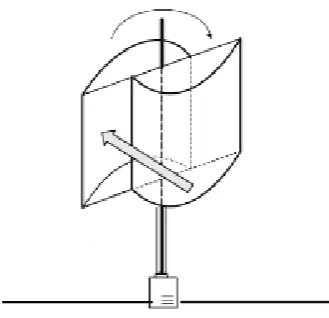
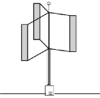
[image:19.595.237.402.564.723.2]The VAWT has more advantages compare to HAWT as it can receive wind from any direction not like HAWT only can receive wind from the front of the rotor. VAWT also able to operate even in low wind speeds area and easier for maintenance since its generator and components are located at the bottom. Besides that, the size of VAWT is smaller than a HAWT which more suitable to be install in residential areas. The VAWT can be further divided into many types based on their designs. The three major types of VAWT that often employed are Savonius type, Darrieus type and Giromill type. Savonius type VAWT was invented by a Finnish scientist, S. J. Savonius in 1922 which is basically consist of two half-cylinder which attach to the rotor and form a S-shape blade from top view (Hardisty, 2009) The design of Savonius type VAWT is shown in Figure 1.1. Darriues type VAWT was invented by a French engineer, G. J. M. Darrieus in 1931 which has two or three narrow curved blade that surround the rotor (Breeze, 2015). The design of Darriues type VAWT is shown in Figure 1.2. However, Giromill type VAWT has been included in the Darriues’s patent which also known as H-rotor which has few straight blades that attached to the rotor by horizontal support (Tong, 2010). The design of Giromill type VAWT is shown in Figure 1.3. Although VAWT is able to operate at low wind speed, however, the efficiency of power generation is lower compare to HAWT (Dvorak, 2014). Hence, the VAWT will be analyze in this study in order to enhance the efficiency of power generation. Among many types of VAWT, only the Savonius type VAWT will be focus in this study.
3
Figure 1.2: Darrieus Type VAWT. (Northrop and Connor, 2013).
[image:20.595.235.402.321.485.2]4
1.2 PROBLEM STATEMENT
The ability of wind energy on replacing the use of fossil fuel resources has been discovered by engineers over the world. The engineers had proved that the wind energy is a potential to become a reliable energy. The wind turbine is the mechanism that receiving wind energy while generator is the mechanism that able to convert the mechanical energy of rotor of wind turbine caused by wind energy to electrical energy. However, the generator available is a high torque generator which needs wind energy with higher speed to initiate the rotation. When wind energy with high speed is applied to the blade of wind turbine, the stress experienced over the blade which receiving the wind energy may exceeds the maximum stress of the blade can withstand.
1.3 OBJECTIVES
5
1.4 SCOPE
6
CHAPTER 2
LITERATURE REVIEW
2.1 TYPES OF WIND TURBINES
Wind turbines are mechanisms that used to convert kinetic energy of wind to mechanical energy through the blades and convert the mechanical energy of rotor to electricity through generator. The electricity generated by the wind turbines can be used as a residential scale power system. Modern wind turbines can be classified in two types based on its rotating axis, which are Horizontal Axis Wind Turbine (HAWT) and Vertical Axis Wind Turbine (VAWT).
2.1.1 HORIZONTAL AXIS WIND TURBINE (HAWT)
7
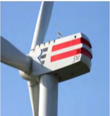
[image:24.595.235.404.265.477.2]is shown in Figure 2.2. This kind of wind turbines are most common used today. This is because HAWT able to receives strong wind due to the height of tower that keeps the blades always at high altitude. Besides that, HAWT is a high efficient turbine because of the blades design that able to receive power from wind continuously when rotates. However, HAWT only able to functions when the wind stream flows from the front of the rotor. HAWT’s blades position need to be rotate according to the wind direction. Furthermore, the maintenance of HAWT is difficult to be carried out due to the position of drive shaft and generator that located at the top of tower.
Figure 2.1: Enercon E-126. (Lafe, 2013)
[image:24.595.226.413.523.720.2]