Structural Analysis and Characterization of Radial Flux PM
Generators for Direct-Drive Wind Turbines
P Jaen-Sola*, A S McDonald
†Wind Energy Systems Doctoral Training Centre, Department of Electronic and Electrical Engineeing, University of Strathclyde, Glasgow, UK, *[email protected], †[email protected]
Keywords: Direct-drive, radial flux permanent magnet generator, structural stiffness, FEA, optimised mass.
Abstract
Wind turbine direct-drive generator structures are analysed in order to optimise and reduce mass. A method for modelling key stiffness parameters including a magnetic air-gap stiffness is outlined. Different approaches are used to parametrically calculate structural stiffness and mass. Finite element and analytical techniques are used to model mode 0 and mode 1 deflections and these can be used along with parametric models of electromagnetically active material.
1 Introduction
The expected increase in energy demand and the recent concerns on climate change have woken up the interest in renewable energies with the wind power industry playing an important role. Over the last years, the use of non-standard electrical generators for offshore direct-drive wind turbines has arisen. In direct-drive machines the generator is directly coupled to the hub meaning that no gearbox is needed in the drive train. This simplification can lead to increases in the system’s efficiency, availability and reliability and a reduction in noise levels. On the other side, low speed generators face a unique set of challenges that need to be addressed in order to compete with high speed geared generators. The input to the direct drive generator is low speed and very high torque. With a stated shear stress and axial length, it is necessary to increase the diameter of the machine and with a number of considerable magnitude loads acting on the generator rotor only robust and stiff machines of substantial weight can deal with such a harsh environment and maintain the small air-gap clearance between the rotor and the stator open.
Direct-drive generators are AC synchronous machines that can be permanent magnet or electrically excited. Permanent magnet generators can be considered superior to electrically excited machines because of their lower weight, improved efficiency and compactness. Permanent magnet generators are often characterized by the orientation of the magnetic flux as it goes across the air-gap, as follows:
- radial flux - axial flux - transverse flux
Although axial flux and transverse flux machines are of significant interest, this paper focuses on radial flux machines. Almost all permanent magnet machines used in larger wind turbines are of this topology. Radial flux machines are popular and will be recognisable to the reader, being similar in construction to conventional synchronous and asynchronous electrical machines. Usually an inner rotor (of generally cylindrical shape) with surface-mounted permanent magnets spins within a stationary armature. Some machines have an outer rotor and inner stator.
The application to wind turbines is unique because of the low speed (in direct-drive turbines) and the requirement for lightweight generators that can be lifted up to and installed on top of high towers.
Electrical and magnetic design and optimisation of these radial flux generators is a well understood subject; however the mechanical design is less well characterised. A critical element of the mechanical design is to produce a structure that can maintain the gap between the rotor and the stator. A good mechanical design would be one that achieves this with a minimum of mass and cost.
Strain, rather than the stress, therefore is the quantity to pay attention to. The key feature in electrical machines is a large force across the air gap which is due to the normal component of Maxwell stress (in the order of 200-400kPa in typical machines). McDonald and Mueller [1] describe various approaches for calculating mass of machine structures in order to deal with this force and uniform deflection (Mode 0 deformation). In [2], McDonald linked the mechanical and electromagnetic design taking disc and arm structures that were used to model radial, axial and tangential deflections in radial flux machines. In axial flux generators, disc models can be used to link the structural dimensions and electromagnetic forces with the deflection.
Tavner and Spooner proposed an approach which described the challenge in terms of stiffness criteria, paying particular attention to mode 1 deformation of the rotor and stator [3]. This paper carries on this work, clarifying the results using finite element modelling and attempts to unite [2] and [3].
2 Structural stiffness analysis
with the aid of computational finite element techniques, such as ANSYS.
2.1 Generator structures
Different rotor and stator structures have been analysed. Figure 1 displays the rotor structures that have been looked at in other papers [2], [4].
[image:2.595.60.254.172.316.2]
Figure 1: Typical rotor structures [4]
This paper focusses on structures where discs connect the shaft to the rotor surface, as they are relatively simple to describe and model.
[image:2.595.44.259.366.467.2]
Figure 2: (a) Generator structure (b) Showing as stiffness 2.2 Structural stiffness study
Figure 2 shows a cross section of a direct-drive generator in a wind turbine. The radial flux generator can be thought of as 4 main elements of stiffness: the bearing (with stiffness = kb),
the rotor structure (with stiffness = ks,r), the magnetic air-gap
stiffness (with stiffness = kM) and the stator structure (with
stiffness = ks,s). The bearing and rotor structure can be
combined as they are in series:
(1)
A force, F, acts on the rotor and stator surfaces (see Section 3) to close the air-gap. If the rotor surface moves by δr
towards the stator and the stator surface moves by δs towards
the stator then the air-gap clearance reduces by (δr+δs). The
force is then equal to
( ) (2)
At the rotor and stator surfaces the structural stiffness gives rise to restraining forces:
(3a)
. (3b)
For the air-gap to be stable, these forces must be equal. By manipulating Equations (2) and (3), the following result can be found:
. (4)
In order to maintain the air-gap with deflections limited to δr
and δs then the equivalent structural stiffness
equals km.
2.3 Deflection modes
As said, the key function of the generator structure is to keep the clearance between stator and rotor. Deformation of any of them can cause severe damage. In [3] the authors observed that localized contact can take place as a result of:
0. Relative radial expansion of the rotor or radial compression of the stator.
1. Expansion and radial relative displacement.
2. Distortion of either or both of the circular surfaces into ellipses (known as ovalising).
3. Distortion with ripples around the circumference. Equation (5) describes these ways of deformation,
̅ ( ) (5)
where δ is the radial displacement at angular position θ, ̅ is the mean radial displacement, is the variation in radial displacement, φ is the orientation of the deformation pattern and n is an integer defining the wave number of the pattern. This wave number pattern gives rise to different mode shapes:
= 0 for deformation of mode 0 (Fig. 3 (a)); = 1 for mode 1 (Fig. 3 (b));
= 2 for mode 2;
and 3 for mode 3 and higher.
Although modes 2 and higher are known to occur in some machines, this paper concentrates on modes 0 and 1.
[image:2.595.305.534.524.655.2]
Figure 3: Rotor deformation. (a) Mode 0, uniform deflection. (b) Mode 1, δ = f (sinθ)
2.4 Case study generator
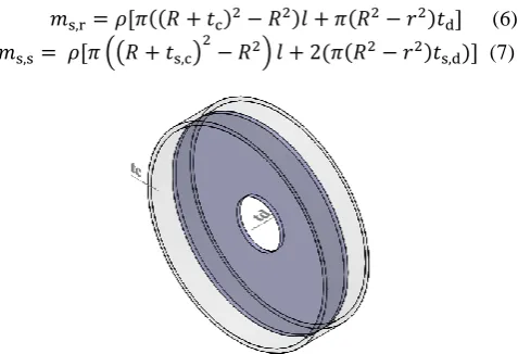
In the rest of the paper a 3 MW wind turbine generator is used as a case study. The steel rotor structure has a 4m diameter and a 1.2m axial length as seen in Figure 4. Dimensions td and
tc have been altered and the structural stiffness calculated
(( ) ) ( ) (6) (( ) ) ( ( ) ) (7)
Figure 4: Rotor structure with cylinder and disc thickness dimensions as varied in this study
3 Air-gap closing force
3.1 Electromagnetic analysis
In order to understand how the magnetic forces and structure interact one first needs to consider some electromagnetic analysis. With the current in the winding known, the flux density distribution, B, in the air-gap can be found as follows,
(8)
with F being the MMF set up by the field (winding or magnets) and armature windings current and P the permeance of the air-gap. Having a pole number of 2p the main air-gap MMF is assumed to be sinusoidally distributed:
̂ ( ) (9)
If we assume that iron in the magnetic circuit is infinitely permeable and we ignore slots then, the air-gap permeance can be approximated as,
̅ ( ) (10)
where ̅ is the mean air-gap permeance, ̅
̅ and is
the amplitude of variation of the air-gap permeance
( ̅) and is the nominal air-gap clearance. μ0 is the
permeability of free space. For a surface mounted permanent magnet machine where the magnetic air-gap and air-gap clearance are different these become ̅
̅ and ( ̅) (where hm is magnet height and μr is
relative permeability).
Substituting Equations (9) and (10) into (8) and neglecting φ leads to the following result:
̂ ̅ ( ) ̂ ( ) ( ) (11)
3.2 Magnetic air-gap ‘stiffness’
One can find the normal component of Maxwell stress σn
with Equation (12), where B is the air-gap flux density,
(12)
By manipulating (11) and substituting into (12), neglecting terms and assuming that ̂ ̂ ⁄ ̅ then
̂ ( ) [
( )
̅ ] (13)
For mode 0 the peak normal stress is ̂
. For non-mode 0, the
peak normal stress is ̂
[
̅]; for a PM machine this
becomes ̂
[ ̅].
Therefore the peak force on the air-gap surface per unit axial length per radian is:
̂ [ ̅ ] (14)
In general terms stiffness, k = F/δ. Taking the peak force per unit length and per radian, as well as the peak deflection
( ̅ ) then Equation (15) gives a magnetic air-gap stiffness. The force is dependent on the air-gap flux density which in turn is dependent on the remaining air-gap clearance. As the deflection increases the force increases. Equation (15) is defined in terms of (2) so that deflection is reduces the original length of the air-gap, :
̅
̂ [
̅] (15)
For mode 0 (Equation (15a)), as air-gap flux density increases this stiffness increases with B2. The stiffness is also proportional to l×R. Importantly the stiffness is inversely proportional to the deflection (as expected a hypothetical scenario of no deflection leads to | | → ∞; that is infinite stiffness).
̅
̂
(15a)
For other modes, stiffness is generally inversely proportional to the peak deflection. This however in Equation (15) is modified by a term
̅ showing that the stiffness is a
function of the degree of variation in deflection.
The job of the rotor and stator structure and any bearing system is to provide sufficient stiffness for the rotor and stator to maintain a certain clearance. Indeed this can be found when Equation (4) and (15) are equal, where ks is the
combined stiffness of the rotor and stator structure and any bearing system. This can be rewritten with Equation (15) to give
̅
̂ [
̅]
. (16)
̅ ̂ [ ̅]
. (16a)
This shows that surface mounted magnet machines (and by implication air-gap windings) have lower structural stiffness requirements.
If the mean deflection is large then the air-gap stiffness for higher order modes can be larger than that for mode 0. It is important to understand how ks varies with the different
modes.
4 Structural stiffness finite element analysis
With the structural requisites understood, finite element studies were carried out. The model was constrained at the shaft and a mesh size of 100mm was utilised [5]. The structures were analysed for mode 1 assuming a deformation of ̅ = 0.0027m and δΔ = 0.0015m in a 5mm air-gap. Looking
at the variations in the flux density within the electromagnetic circuit a maximum normal stress of 411kPa was placed on the top of the structure whereas the minimum normal stress was located at the bottom (value 335kPa) with the stress varying sinusoidally. The thicknesses of the cylinder, tc
,
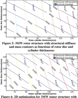
and the disc,td,were varied and the FE results plotted. Figure 5 is a plot of
stiffness and mass, which can be employed to approximate the minimum rotor mass, where the disc thickness and the cylinder thickness are independent variables.
4.1 Rotor analysis
The rotor structure in Figure 4 was subjected to a sinusoidally distributed expansion load acting on the rim. The following are the material properties of the steel structures: Young’s modulus, E = 2.1x10¹¹ Pa, Poisson’s ratio, v = 0.3 and mass density, ρ = 7850 kg/m3.
4.2 Stator analysis
The same approach was followed to evaluate the stator structure. With a sinusoidally distributed compression load acting on the inner face of the stator rim the thicknesses of the discs and the cylinder were varied. Figure 6 shows a plot that can be used to estimate the minimum mass required for the stator structure.
For instance, using Equation (16a) to calculate the structural stiffness needed to maintain the stability of the air-gap, ks =
2.8×10⁹ N/m. Assuming a stiffness of the bearing, kb = 3×10¹⁰
N/m, the equivalent stiffness for the entire structure can be estimated from Figures 5 and 6. For this example, ks,r =
7.5×10⁹ N/m. If ks,r and kb are substituted into Equation (1) the
equivalent stiffness for the rotor structure is keq,r = 6×10⁹ N/m.
Replacing keq,r and ks,s, (which for this example would be
equal to 6.1×10⁹ N/m), into Equation (4) gives ks = 3×10⁹
N/m. Once the issue of the radial stiffness has been addressed, a typical scenario might have a further constraint that the discs of the rotor and the stator must have 80mm thickness due to torque or natural frequency requirements. In this case it can be observed that the minimum mass for the rotor is ms,r =
22500kg and the minimum mass for the stator, ms,s = 26500kg
giving a total mass of 49000kg.
Entering into the plots displayed in Figures 5 and 6 with ks,r
and ks,s respectively, multiple options can be adopted allowing
minimisation of the mass of the whole structure.
[image:4.595.303.554.208.524.2]However, it is worth pointing out that the use of FE methods presents several disadvantages. Among them, the fact that results are only correct for one set of air-gap loads stands out. Additionally, special care must be taken when defining the settings of the analysis and the simulation studies take a long time. So as to mitigate these downsides an analytical approach was developed.
Figure 5: 3MW rotor structure with structural stiffness and mass contours as functions of rotor disc and
cylinder thicknesses
[image:4.595.305.555.210.336.2]Figure 6: 2D optimization for 3MW stator structure with structural stiffness criterion
Figure 7: Rotor structure split into disc and cylinder models
5 Analytical characterisation of disc structures
Different approaches are available to characterize disc structures. Whereas the use of FE techniques bring on certain difficulties that have been already explained, analytical approaches allow the user to find the structural stiffness of the components by introducing their dimensions and their material characteristics into the equation.
Rotor cylinder thickness(mm)
R o to r d is c t h ic k n e s s (m m ) 6.4x10 9 7.5x10 9 8.6x10 9 9.7x10 9 10.8 x10 9 11.9 x10 9 13x10 9 14.1 x10 9 20000
22000 24000 26000
28000
30000 32000
70 80 90 100 110 120
70 80 90 100 110
120 Structural stiffness(N/m)Structural mass(kg)
Stator cylinder thickness(mm)
S ta to r d is c s t h ic k n e s s (m m ) 5.5x10 9 6.1x10 9 6.7x10 9 7.3x10 9 8x10 9 8.6x10 9 9.2x10 9 9.9x10 9 10.6 x10 9 23000 25000 27000 29000 31000
33000 35000 37000
39000 41000
70 80 90 100 110 120
70 80 90 100 110
5.1 Analytical approach for rotor structures
The structural stiffness of the rotor can be predicted by combining the disc and cylinder structures in series:
(17)
Figure 7 shows a graphical representation of how the stiffness of the rotor structure can be estimated.
5.2 Rotor disc model: central hole and loaded boundary
The approach proposed by Benham et al has been used in this paper to examine the stiffness for the disc structure. In [6], the authors assumed a disc structure with a central hole and unloaded boundaries that rotates at a constant velocity and therefore is subjected to stresses induced by centripetal acceleration. Since the approach presented in this paper considered a disc structure with a central hole subjected to an expansion load uniformly distributed along its edge and ω → 0, Benham’s model was to some extent modified to match these features and help corroborate the models. The stress-strain relationship is,
(18) where σr is the radial stress and σθ is the angular stress.
As no motion has been considered the radial stress can be found by either
(19a)
(19b)
The angular stress can also be determined using any of the two following equations, or . Assuming that no load is acting on the central hole then
. (20)
Subtituting this into Equation (19a) and rearranging then
(
)
. (21)
Radial strain with for axial symmetry gives
(22)
and if Equation (22) is rearranged and εr in Equation (18)
replaced the following results can be found,
( ( ) ( )) (23)
(
(
( )(
)
))
(24)
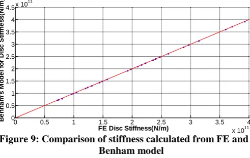
Figure 9 illustrates the comparison between this model and the FE results. An excellent agreement is achieved as Benham’s model stiffness is equal to the FE stiffness with
.
[image:5.595.306.552.193.349.2]However, this approach only works for mode 0. Hence, an approach that accurately predicts the structural stiffness of this rotor component for different modes of deflection needs to be found.
Figure 9: Comparison of stiffness calculated from FE and Benham model
5.3 Rotor disc model as found from FE results
Looking at the rotor components separately is possible to find physically meaningful algebraic equations that describe with precision their structural behaviour. In this paper, analytical techniques based on the principle of dimensional homogeneity have been used [7]. In the case of the disc structure, if it is assumed that its stiffness depends on the Young’s modulus, E, thickness, td, Poisson’s ratio, v, and R-r,
where r is the radius of the shaft, we can proceed as follows. Let
[ ]=[ ( ) ]. (25)
Replacing the dimensional combination for each factor in terms of [ ], force, and [ ], length, it can be obtained that
[ ]=[ ] (26)
Note that the Poisson’s ratio is a dimensionless variable. Equating powers it is obtained that a=1 and -1 = -2a+b+c. It can be observed that the analysis is unable to tell the powers of the thickness and the length. Nevertheless, they can be estimated by looking at how they vary with the stiffness, which was approximated using the FE data collected in Section 5.2. The implementation of a constant was necessary so that the equation could be finally balanced.
( )
( ) (27)
Note that a dimensionless variable, γ, which depends on the mode of deflection, has also been introduced. With it, the stiffness of the rotor components can be calculated taking into consideration the degree of the deflection mode. γ is equal to
. Mode 0 is by definition when γ = 1.
A comparison between the results for mode 0 obtained with Equation (27) and data retrieved from the FE simulation
0 0.5 1 1.5 2 2.5 3 3.5 4
x 1011 0
0.5 1 1.5 2 2.5 3 3.5 4 4.5x 10
11
FE Disc Stiffness(N/m)
B
e
n
h
a
m
's
M
o
d
e
l
fo
r
D
is
c
S
ti
ff
n
e
s
s
(N
/m
studies is shown in Figure 10. As it can be seen, a good agreement was achieved over the whole range. The data has a R2 = 0.9945 with regards a line with gradient of one, passing through the origin.
Figure 10: Equation vs. FE disc stiffness
5.3 Rotor cylinder model as found from FE results
A similar methodology was tracked for the rotor cylinder. Assuming kc = f(E, tc, l, R), the dimensional analysis was
carried out. As with the disc, the study could not predict all the powers of the variables so they had to be found by looking at their variation of stiffness with each parameter.
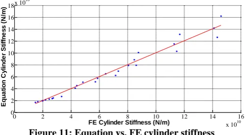
Equation (28), which accurately describes the behaviour of the cylinder structure, was found after the analysis,
( ) ( )
( ) (28)
where l is the cylinder axial length. Again a comparison between the equation results and the data from the FE analyses for mode 0 is presented in Figure 11. A satisfactory accuracy was achieved as shown by a straight line of gradient 1, passing through the origin, with and R2 = 0.9721 for Equation Cylinder Stiffness = FE Cylinder Stiffness.
Figure 11: Equation vs. FE cylinder stiffness
5.4 Rotor stiffness model
Once the stiffness of the disc, ks,d, and the stiffness of the
cylinder, ks,c, were calculated, they were substituted into
Equation (17). It was observed that the results consistently differed from the FE data by a factor of α = 1.3. This is probably because the cylinder stiffness is evaluated with a undeformed inner bore, but in reality the inner bore is significantly deformed. The final equation to calculate the stiffness of the rotor would be as follows,
(
). (29)
This can be used with Equations (16) and (16a) to reduce the structural mass given by Equations (6) and (7).
6 Conclusions
A stiffness design approach can be employed to ensure that the air-gap remains open. The air-gap attraction is modelled as a magnetic stiffness and the rotor and stator structures can be modelled either analytically or using a finite element technique. A hybrid approach (using results from finite element methods) is advantageous because it is quick to use and also takes into account mode 1 deflections which can dominate in some scenarios.
References
[1] A. McDonald, M. Mueller and H. Polinder, “Structural mass in direct-drive permanent magnet electrical generators,” IET Renewable Power Generation, Vol. 2, no. 1, pp. 3-15, March(2008).
[2] A. McDonald, “Structural analysis of low speed, high torque electrical generators for direct-drive renewable energy converters,” Ph.D dissertation, University of Edinburgh, Edinburgh, Scotland, 2008.
[3] P. Tavner and E. Spooner, “Light Structures for Low-Speed Machines for Direct-Drive Applications,” in Proc. International Conference on Electrical Machines, Chania, Greece, 2006.
[4] J. Stander, G. Venter and M. Kamper, “Review of direct-drive radial flux wind turbine generator mechanical design,” Wind Energy, vol. Published online in Wiley Online Library (wileyonlinelibrary.com)doi:
10.1002/we.484, 2011.
[5] A. Zavvos, “Structural Optimisation of Permanent Magnet Direct Drive Generators for 5MW Wind Turbines,” Ph.D dissertation, University of Edinburgh, Edinburgh, Scotland, 2013.
[6] P. Benham, R. Crawford and C. Armstrong, Mechanics of Engineering Materials, Prentice Hall, Second Edition (1996).
[7] R. Pankhurst, Dimensional Analysis and Scale Factors, London: The Institute of Physics and The Physical Society , 1964.
0.5 1 1.5 2 2.5 3 3.5 4
x 1011 1
2 3 4x 10
11
FE Disc Stiffness(N/m)
E
q
u
a
ti
o
n
D
is
c
S
ti
ff
n
e
s
s
(N
/m
)
0 2 4 6 8 10 12 14 16
x 1010 0
2 4 6 8 10 12 14 16 18x 10
10
FE Cylinder Stiffness (N/m)
E
q
u
a
ti
o
n
C
y
li
n
d
e
r
S
ti
ff
n
e
s
s
(
N
/m
[image:6.595.43.294.463.601.2]![Figure 1: Typical rotor structures [4]](https://thumb-us.123doks.com/thumbv2/123dok_us/1638007.117171/2.595.60.254.172.316/figure-typical-rotor-structures.webp)