Use of Orbiting Reflectors to Decrease
the Technological Challenges of Surviving the Lunar Night
Russell Bewick*, Joan-Pau Sanchez and Colin R. McInnesAdvanced Space Concepts Laboratory, University of Strathclyde Glasgow, G1 1XJ, United Kingdom
In this paper the feasibility of using lunar reflectors to decrease the technological challenges of surviving the lunar night is investigated. This is achieved by attempting to find orbits in the two-body problem where the argument of periapsis is constantly Sun-pointing to maximise the time spent by the reflectors over the night-side of the Moon. Using these orbits the ability of reflectors of varying sizes to provide sufficient illumination to a target point on the surface is determined for scenarios where a latitude band is constantly illuminated and a scenario where a specific point is tracked. The optimum masses required for these far-term scenarios are large. However, a nearer-term scenario using low altitude orbits suggest that the effective duration of the lunar night can be reduced by up to 50% using a set of 300 parabolic reflectors of 100m radius with a total system mass of 370 tonnes. A system is also demonstrated that will allow a partial illumination of the craters in the Moon’s polar region for a mass up to 700kg.
1. INTRODUCTION*
In recent years there has been significant interest in both the human and robotic exploration of the Moon. The scientific and economic reasons for a return to the moon are varied and in some cases disputed and so shall not be discussed here. This paper shall propose a method to mitigate one of the key difficulties with long-term lunar exploration; surviving the lunar night.
The key difficulties associated with lunar exploration arise from the dynamics of the Moon’s orbit around the Earth and absence of an atmosphere. The tidally locked orbit with a period of approximately 27.5 days results in long periods of sunlight and darkness. This creates a challenging thermal environment where the surface temperature, unfiltered by an atmosphere during the day, can reach a maximum of 390K in the equatorial regions whilst during the long night, where there is no atmosphere to insulate/trap solar heat, temperatures can reach a minimum of 100K. The length of the lunar night makes the use of solar panels to power electric heaters unfeasible and hence heat must be generated, or stored, by other methods.
The most straightforward solution to the problem of the lunar night is to use Radioisotope Heater Units (RHUs). These devices generate heat through the radioactive decay of Plutonium-238 (or other radioactive sources) and, due to its long half-life, can last for many years. However, there are many challenges to using this method [1], most notably special considerations are required to shield sensitive instruments from the radiation source and there is currently a shortage of Plutonium-238. Additional issues, such as their high cost, make surviving the lunar night without such devices desirable.
*
To achieve this, heat or energy storage is necessary in combination with improved insolation, such as placing critical systems such as batteries in thermally isolated boxes [1, 2]. The required mass of secondary batteries and idealised thermal capacitors to enable a lander to survive on the lunar surface has been estimated in [1]. It was found that to survive the lunar night, without a continuation of normal operations, would require an excessive mass fraction for storage devices, particularly for landers below 600kg.
Another possible solution is to utilise the low thermal conductivity of lunar regolith and bury a lander or crewed lunar base. It has been found that the temperature of the lunar sub-surface remains constant below a depth of order 1m [3]. Clearly this method is not suitable for a rover or lunar lander, however it may be suitable for a crewed lunar base.
This paper aims to investigate the possibility of reflecting sunlight onto the lunar surface to enable the survivability of missions that would otherwise not live through the lunar night, such as the SELENE-2 mission [4]. This shall be achieved by a discussion of a family of non-Keplerian orbits [5] where a series of orbiting reflectors in a forced Sun-synchronous orbit are used to reflect sunlight towards;
the centre of the moon
a latitude band on the lunar surface
a given point on the lunar surface, tracking it whilst orbiting
provide sufficient illumination to the target point or area over the range of orbital parameters and reflector sizes can finally be found. Before the orbital dynamics of these scenarios are discussed reflector concepts must first be introduced, followed by an analysis of the reflector requirements.
2. REFLECTOR SYSTEMS
2.1. Reflector Image
The physical aspects associated with the reflection of light onto a planetary surface have been dealt with previously in [6]. In summary, the area of the reflected image of the Sun at a given distance y away from an unfocused reflector can be given as;
2 2 2
4sin
i r
A
D
y
(1)where Dr 2
is the diameter of the reflector, ε is the elevation of the reflector above the surface and β is the solid angle subtended by the Sun. The value of β at the Earth’s distance from the Sun is 0.0093. It can also be shown that for a parabolic reflector, where y is also the focal distance, the image area is given by;
2 2
4sin
p
y
A
(2)Subsequently the fraction of the normal solar constant, defined later as η, supplied by the reflector over this area can be calculated by;
0 ,
cos( )
i r
i p
I
A
I
A
(3)with ρ being the reflectivity, or efficiency, of the reflector, Ar the area of the reflector and α the angle between the
incoming and reflected rays at the reflector. The value of ρ used throughout this paper is 0.9 [7]. Substituting in eqn. (1) and eqn. (2) and the area of the reflector, Ar=π(Dr/2)2
gives;
1 2
0
cos( ) sin
1
i
r
I
y
I
D
(4)
and
2
0
cos( ) sin
r pI
y
I
D
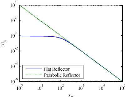
(5) [image:2.595.314.514.75.230.2]We can define a variable, χD, as the distance to the target in units of reflector diameter, to analyse the behaviour of these two equations. The results of this can be seen in Fig. 1.
Fig. 1- Concentration ratio as a function of focal point distance in terms of reflector diameter.
The results in Fig. 1 show that above a distance equal to approximately 200 times the reflector diameter there is little difference between the results of the flat and parabolic mirrors. For any reasonable advantage of using a parabolic mirror the maximum value of χD is nearer 100. Using eqn. (4) and (5) the ability to provide sufficient illumination for a reflector in a given orbit or position can be analysed.
2.2. Required Insolation
Before proceeding, the quantity of sunlight required to enable night-time survival must be determined. Since the Moon experiences extremes of temperature in both the night and day periods a value reasonably removed from both extremes will be required. A benchmark shall be calculated by estimating the solar insolation required to give a surface temperature of 273K. The solar constant fraction, η, was calculated using a thermal model of the surface as seen in Fig. 2. In this model the surface temperature, TS, is found by the balance of incoming and
outgoing radiation and conduction between the surface and subsurface.
Fig. 2 - Model showing the main influences on the lunar surface temperature
The model can be expressed as an energy balance equation, eqn. (6), from which η can be calculated.
4 0
[image:2.595.43.284.622.720.2]In this equation the solar constant, I0, used is 1368 Wm -2
[8], the lunar bond albedo, A, is 0.11 [1], the thermal emissivity of the surface,
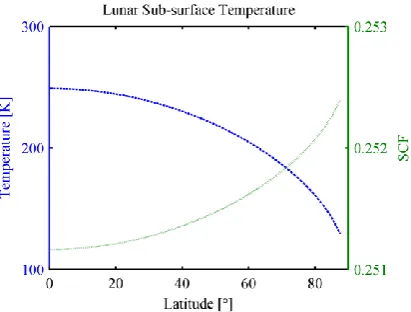
BB, is 0.97 and the thermal conductivity of the Moon, κ, is 9.3x10⁻³ Wm-1K-1 [9]. The temperature of the sub-surface, TSS, changes with latitude, [image:3.595.52.258.226.382.2]as can be seen in Fig. 3, with the maximum at the equator 249K [1]. The solar constant fraction is required to ensure a surface temperature 273K in the equatorial regions can thus it can subsequently be calculated to be η=0.251. As can be seen in Fig. 3 due to the low thermal conductivity of lunar regolith little extra illumination is required to achieve a surface temperature of 273K for higher latitudes.
Fig. 3 - Lunar sub-surface temperature and required solar constant to raise the surface temperature to 273K as a function of latitude.
2.3. Lander Thermal Model
Alternatively, a system model of a lander, as described in Ulamec [1], can be used to define a more accurate value of η. In this model the mass fraction, χ, of secondary batteries (SB) and thermal capacitors (TC) required to survive the lunar night, as a function of lander mass, can be calculated. This was achieved by using the assumption that the lander is a cube, coated on all sides by MLI, the volume of which scales with the mass fraction.
The volume of the cube is found using the estimate of the mass fraction of the energy storage device and the densities of the lander, ρL, and storage device, ρSB, from
which the surface area, AL, can be calculated; 2/3
1
L L L
SB L
A m
(7)
Here the lander mass is seen as mL whilst βL is a geometry
coefficient that describes the ratio of total to cross-sectional surface area, i.e. βL=6 for a cube. Using the total surface
area the heat loss can be estimated;
1 2
2
L A
q h T T (8)
where ΔT1 and ΔT2 are the temperature differences between the lander and the surface and sky respectively and h is the
heat transfer coefficient of an MLI blanket. The total energy storage requirement to survive the lunar night, of length N, for the lander with mass, mL, can be estimated and
the mass fraction of storage required, with energy density C, can be determined;
L qN Cm
(9)
Thus the true mass fraction for energy storage can be determined for a given lander mass by solving;
2/3
1/3
1 2
( )
(1 )
0 2
L
L L
SB
h T T N m C
(10)
The values for the constants used are summarised in Table 1. It is shown in [1] that the mass fraction of secondary batteries is consistently lower than that for thermal capacitors and so only secondary batteries shall be considered here. Using secondary batteries has the added advantage over thermal capacitors that if the stored energy is used to provide power for night time operations, this energy will be dissipated as heat, with the exception of that used for communications, which will thus have a similar effect as providing power to electrical heaters.
Symbol Parameter Value
ρSB
Secondary Battery
density 1,250 kg m
-3
ρL General lander density 220 kg m-3
h Heat transfer coefficient
(MLI) 0.04 W K
-1 m-2
βL Geometry coefficient 6
TL Lander temperature 283 K
C Energy density (SB) 136 Wh kg-1
N Length of lunar night 384 h
Table 1: Values used to determine the mass fraction of secondary batteries (SB) required to survive the lunar night [1].
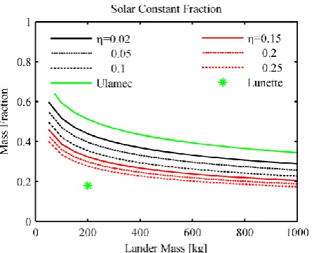
[image:3.595.318.548.383.536.2]sky temperature remains constant. It can be seen in Fig. 4 that for increasing values of η the mass fraction of batteries required decreases, with the greatest gain being made for relatively low illuminations. The benefit of increased illumination above η=0.15 appears to be small with a battery mass fraction saving of just under 50% for the largest lander mass considered. For off-zenith illumination there is little change initially but for large deviations away from the zenith angle there mass fraction of batteries required increases considerably.
Shown in Fig. 4 is a data point for a proposed lunar lander network Lunette [2]. This lander survives the lunar night by thermally isolating the most sensitive components, such as batteries and data storage etc, in a warm electronics box (WEB). This box is insulated with MLI and will lose heat at a rate of 3W which is significantly lower than the calculation suggested by the use of eqn. (8). An estimate of the value of η required to offset this loss of 3W can be performed by estimating the volume of the box as in eqn. (7), with the mass of batteries being 36kg with a total box mass of 73kg (estimated using data found in [2]). Now the sky temperature required to offset this thermal loss again assuming only one face is illuminated can be estimated to be the equivalent of η=0.1. This value shall be used as the minimum necessary to survive the lunar night with the maximum being η=0.15, beyond which the mass fraction saving comes at a much higher cost of η
3. REFLECTOR ORBITAL DYNAMICS
[image:4.595.313.542.74.252.2]This study will investigate two main orbits from which sunlight will be reflected onto the surface. The orbital dynamics of both these systems will assume that the third body perturbations of the Sun and Earth are minimal providing that the orbit does no cross the Hill radius of the Moon, at a distance of order 60,000km. Similarly, the harmonics of the lunar gravitational potential will be assumed to be negligible with the high orbits considered. These assumptions are made to determine the initial feasibility of the concepts proposed.
[image:4.595.50.274.571.751.2]Fig. 4 - Mass fraction of secondary batteries required to survive the lunar night with differing average values for the solar constant fraction.
Fig. 5 - Mass fraction of secondary batteries required to survive the lunar night with differing elevation angles for a solar constant fraction of 0.25.
3.1. Forced Sun-pointing orbits
Previous studies [5] propose the use of a solar sail to enable a spacecraft to explore the Earth’s geomagnetic tail by precessing the orbit apse line at the same rate as the orbital motion of the Earth around the Sun. The same dynamics can be exploited here to artificially precess the elliptical orbit of a lunar reflector, ensuring that the reflector apocentre is always above the lunar night-side, maximising the fraction of the orbit which can be used for illumination. Continuous low-thrust propulsion can be used but a much more attractive solution is provided by the use of solar radiation pressure on the reflector. The characteristic acceleration of the solar sail, a0, that is required to precess the orbit apse line at the same rate as the Sun, S, can be found using the Gauss equation [10];
2
d
cos 1 sin
d
r r
R f T f
f e p
(11)
where ω is the argument of pericentre of the orbit, r is the distance between the solar sail and centre of the Moon, μ is the gravitational parameter of the Moon, p is the semi-latus rectum, R and T are the radial and transverse components of the acceleration on the solar sail and f is the true anomaly. For a sun-pointing reflector the solar radiation pressure acceleration can be defined as;
2 0
cos
cos ( )
sin
S
R f
a
T f
(12)
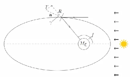
Fig. 6 - Geometry of the centre-pointing lunar reflector system
Moon-centre pointing
This scenario shall assume that the reflector is orientated such that the reflected sunlight is directed towards the centre of the Moon. The geometry of this configuration can be seen in Fig. 6 where the angle γ can be seen to vary as;
2
f
(13)This results in the radial and transverse acceleration components being;
2 0
2 0
cos cos
sin sin sin
cos 2 2
2 R
a T
a
f f
f
(14)
Now the Gauss equation can be integrated over an orbit to give the precession of the perigee;
2 2
1 0
21 2
. 3
4 4 3 3
( 1) 12 3
tan 2 1
1
2 (1 ) 1
a e a
e e e
e e e e
e e e
(15)
where the change in semi-major axis and eccentricity is zero due to the symmetry of the solar radiation pressure acceleration components. Since the orbit period is defined
as 3
0 2 /
T a and the rate of precession must be S the required acceleration can be found to be;
2 0
2
1 3
2 (1 )
.8 4 3 3
( 1) 12 3
tan 2
1 2 (1 )
.
e S
e
a e e
a
e e e e
e e e
(16)
An additional factor that must be also taken into account is the effect that an eclipse has on the precession of the orbit. This is due to the necessity of solar radiation pressure to provide the acceleration on the reflector. Additionally, during eclipse illumination of the surface will not be possible. Low altitude orbits will have a higher proportion of the orbit in eclipse and will therefore require a higher acceleration to be continually Sun-pointing.
To incorporate eclipses eqn. (11) must be integrated between true anomalies of π and fE,1 and from fE,2 to 3π/2.
The integrations do not cover below π and above 3π/2 as it is assumed that within this region the lunar rover or base will be in sunlight and hence no illumination is required. During this phase of the orbit the reflector will be edge-on to the Sun and will not provide any acceleration. This integration can be performed analytically, but the lengthy result is not given here explicitly.
The accelerations required for the simple precessing orbit and the Moon-pointing scenario including eclipse periods can be seen in Fig. 7, and Fig. 8 respectively. This result shows that for the Moon-pointing scenario the acceleration necessary is increased, approximately be a factor of 4.
Fig. 7 - Acceleration required for a simple forced orbit to precess at the same rate as the Sun.
[image:5.595.315.534.371.512.2] [image:5.595.321.533.560.692.2]Moon-centre pointing with latitude band
In this scenario the reflector will also be orientated within the orbital plane such that the sunlight will be reflected towards the centre of the Moon. The additional in this scenario is that there will also be an out-of-plane orientation. This out-of-plane angle will be added so that the reflector can target a specific latitude on the Moon’s surface. As the distance to the centre of the Moon varies throughout the orbit this out of plane angle will vary.. This will allow smaller reflectors to be used to reach higher latitudes. Due to this new method eqn. (14) can be modified to give;
2 0 sin cossin cos 2
2 2 cos cos f f f R a T (17)
where θ is the out-of-plane pitch angle of the reflector. This equation describes the acceleration within the plane but there will be an additional out of plane acceleration component;
20 sin 2 cos sin
z
f
a a
(18)
It is assumed that this can be offset by the use of low-thrust propulsion. The geometry of this scenario as seen from above is the same as that in scenario 1. An analytical expression can be found to describe the out of plane pitch angle for any point on an orbit for a given latitude target;
sin tan cos M M r r r (19)
where r=a(1-e2)/(1+ecos(f)) is the reflector orbit radius. This scenario can be integrated numerically to give the required acceleration.
Moon tracking
For this scenario the rover or lunar base shall be assumed to be on a single point on the lunar surface. Then as the Moon rotates the reflectors will orbit the Moon, reflecting sunlight onto the surface when above the horizon. A minimum elevation angle of 15o is assumed. The reflectors will not be orientated towards the centre of the Moon in this case and so the analytical expressions to determine the acceleration required to maintain a sun-synchronous orbit cannot be used. Therefore a numerical method will be used to determine the angle between the Sun and normal vectors required to reflect sunlight, with the radial and transverse accelerations being subsequently determined.
The required acceleration will be determined by calculating the difference between the acceleration vector required to reflect sunlight onto the target point and the vector calculated in eqn. (14). At the times when the
reflector is not above the surface it will revert to the Moon-centre pointing scenario and thus will not require low-thrust propulsion to offset the acceleration vector.
3.2. Displaced polar orbit
[image:6.595.322.541.254.386.2]The final type of orbit that will be discussed is a circular non-Keplarian polar orbit. This is essentially a circular polar orbit, however due to the effect of solar radiation pressure the orbit is displaced along the anti-Sun line. This is achieved if the reflector assumes a constant attitude in a cylindrical polar coordinate system. This type of orbit has been discussed in [11] for the purpose of climate engineering on Mars. The geometry of the problem can be seen in Fig. 9.
Fig. 9 - Geometry of the displaced circular polar orbit under the influence of solar radiation pressure.
In cylindrical polar coordinates the equations of motion for a reflector are [11];
2
2
3 2
2 cos sin 0
2 0
cos 0
p
p p p p p p
p p
p p p p
p
p p p
p p a r r z z a r r (20)
where ap is the characteristic acceleration of the reflector.
For this type of orbit to exist it is required that p 0 and 0
p
z
. Then, from eqn. (20) it can be found that;
2 tan 1 ˆ p p p z
(21)
where ˆ2 3
/rp
. The characteristic acceleration is found to be;
3/ 22 2
ˆ 1 tan
p p p
a z (22)
From Fig. 9 the required angle αp can be found
1 1
tan 2
p P
p z
(23)
Now using eqn. (21) and (22) the angular velocity and characteristic acceleration can be found for a given set of ρp
and zp. It is a pre-requisite of the system that the length of
ρp must be greater than the radius of the Moon to be able to
reflect sunlight. Also it has been noted in [11] that for these orbits to be stable ρp>4zp. Using this limitation the
minimum angle away from the Sun-line that can be illuminated can be calculated to be 76°. This offers both positive and negative effects; the reflector can reach high latitudes without the need for low-thrust propulsion to offset the out-of-plane thrust, as is the case for the precessing elliptical orbit. However, if these displaced orbits were used to illuminate a target in the equatorial regions there would likely be a large period between passes, around 85% of the night time. This is likely to be offset slightly by the increase in image size observed due to the non-point source qualities of the Sun, however, using a deliberately dispersed beam, with a large spot size, to reduce the gap will likely be inefficient.
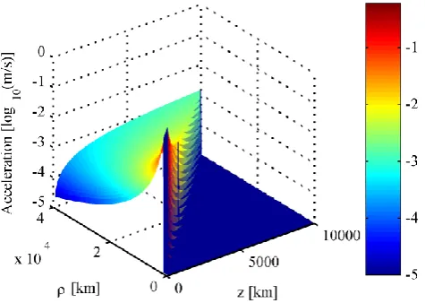
Fig. 10 - Acceleration (in units of log10(ms-1)) required to enable a reflector to be positioned in a displaced polar orbit for varying orbital parameters.
The acceleration required by a reflector in a displaced polar orbit can be seen in Fig. 10. The acceleration is clearly greater than that required for the precessing ellipse, however this will have the effect of placing a minimum requirement on the area-to-mass ratio which will force a significant reduction in the overall system mass. The reflector loading required for a displaced polar orbit can be seen in Fig. 11. Clearly for lower orbits the sail loading becomes more challenging to achieve, especially considering that this takes into account the mass required for other subsystems such as control and communications etc. For these reasons areal densities below 1g/m2 may be unfeasible though they are theoretically possible [12]. Those reflectors that are along the ρ=4z boundary also appear to have a relatively low areal density as they appear to intersect continuously with the 1g/m2 plane seen in Fig. 11.
Fig. 11 - Sail loading required for displaced polar orbits with varying values of z and ρ. Also shown is a plane for a sail loading of 1g/m2.
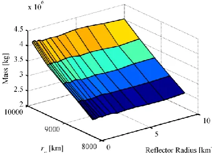
To offset the problem of long periods with no illumination it is desired that the reflector will be able to be directed at a point along the Sun-axis to decrease the maximum angle from the Sun-line. The angle that a reflector can reach for different fractions of rM and varying
distances to the centre of the Moon, rp, assuming that the
[image:7.595.313.560.90.256.2]reflector is at an angle of 76° to the x-axis can be seen in Fig. 12. It can clearly be seen that large distances are required to enable the equator to be targeted which will lead to a reduction in the intensity of reflected sunlight.
Fig. 12 - Minimum latitude achievable for displaced polar orbit for a range of distances and target positions, as a fraction of the lunar radius.
4. RESULTS
The mass of reflector required for each scenario can be estimated using the required acceleration. The acceleration on a reflector due to solar radiation pressure can be expressed as;
0 R
R R
R
I A
a
C
c m
(24) [image:7.595.50.288.359.528.2] [image:7.595.317.545.430.605.2]the coefficient of reflectivity (assumed to be equal to 1.8), c is the speed of light and mR is the reflector mass. Setting the
acceleration in eqn. (24) equal to the characteristic acceleration required for a given orbit type enables the area-to-mass ratio to be calculated for a reflector to be stable on a given orbit. Now since the area of the reflector can be selected the total reflector mass can be determined.
For the precessing ellipse cases the mass and solar constant fraction, calculated using eqn. (4) and (5), are calculated for semi-major axes within the range 2,000km≤a≤30,000km, eccentricities within 0.01≤e≤0.9 and for a range of reflector radii with the lower bound of 100m. The range of semi-major axis was chosen to reduce the influence of the third body perturbation of the Earth and the uneven gravity field of the Moon by reducing the time spent in high altitudes and low altitudes. From these data points a Pareto front is then constructed to show the range of optimal solutions. The number of reflectors required to provide the solar constant fraction η of 0.1 can then be optimised for all the entries along the Pareto front. From this the total system mass can be calculated.
When the value of η is calculated for a specific point or latitude the solar constant received by the lander and ground are determined differently. It is considered that the lander will receive a solar constant fraction with a value equal to η on a single face, under the assumptions discussed previously. The solar constant received by the ground, however, must take into account the elevation angle of the reflector above the surface which results in the solar constant per unit area of the surface being η sinε.
What must additionally be taken into account is the system mass that is required to maintain a stable orbit using low thrust propulsion, where the assumptions of tracking or latitude pointing scenarios apply. This can be achieved by the use of the rocket equation where the mass fraction of a spacecraft remaining after a change in velocity, ∆v, is determined using;
0 0
1
ln
sp
m v I g
m
(25)
where Isp is the specific impulse of the propulsion system
(assumed to be 3,000s), g0 is the acceleration due to gravity at Earth and m0 and m1 are the initial and final masses respectively. The change in velocity required over the period of an orbit for the case of the latitude pointing system can be determined by the integration of eqn. (18) for the first orbit. After the initial orbit the reduction in mass will lead to a larger characteristic acceleration as can be calculated in eqn. (24). Thus, after the initial orbit the additional acceleration within the plane must be offset as well as the out of plane components. The same principles apply to the Moon tracking scenario with the addition that the required acceleration vector must be calculated numerically.
4.1. Moon-centre pointing
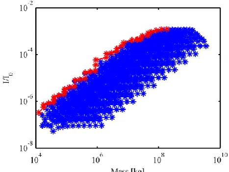
For the basic Moon-centre pointing scenario the values of η and mass are calculated under the assumption that the reflector must be able to reach a minimum latitude at the spot’s maximum diameter, i.e., when the reflector is at apoapsis. This sets a minimum bound on the reflector size with the maximum being calculated to give a reasonable range of values. The data points with the corresponding Pareto front for a minimum latitude of 0.1° using a single reflector can be seen in Fig. 13.
Fig. 13 - Plot of mass and solar constant fraction data points, with corresponding Pareto front, for a Moon-centred scenario with a minimum latitude of 0.1° using a flat reflector.
The mass ranges greatly with the general trend being that increased mass leads to a higher value of η, since the higher masses correspond in general to larger reflectors. The Pareto fronts for the full range of minimum latitudes can be seen in Fig. 14 for the flat reflector and Fig. 15 for the parabolic reflector. There is a smaller range of latitudes for the parabolic case as the spot sizes for these reflectors are smaller and hence will not illuminate the higher latitudes. Also shown in these figures are lines representing the level of light that is observed due to the natural reflection of light from the Moon and Earth viewed at the opposite body respectively.
[image:8.595.313.547.198.373.2]Fig. 14 – Pareto fronts for the Moon-centred scenario for a range of minimum latitudes using a single flat reflector.
On a close inspection of Fig. 14 and Fig. 15 it can be observed that for the low mass portion of a given Pareto front the results are the same for the flat and parabolic mirror results. However for the larger mass portion of the same Pareto front the value of η provided by the parabolic reflector is greater than that for the flat reflector case. This is due to the results described in Fig. 1. As stated previously the desired value of η is 0.1 and it can be seen in the results for the Moon-centre pointing case that this is achievable with the use of a single reflector. However, on closer inspection of the radii of the reflectors involved the scenario appears much less feasible. For example to generate a band which covers a maximum latitude of 1° requires a 3km radius reflector. To achieve η=0.1 with a single mirror would require a very large radius. It is possible to achieve this value using multiple mirrors though for this type of scenario it is unfeasible to do so as there is little flexibility in the system. For example should a rover mission wish to travel beyond a few degrees latitude the reflector diameter would be too large to be feasible in the near term.
When the optimisation is performed to determine the required number of reflectors the masses seen in Fig. 14 and Fig. 15 will increase. As stated previously the target η is 0.1 and in the optimisation there is a required tolerance of ±0.005. The minimum mass results for the case of the 0.1° band are 5.3x10⁹kg and 3.8x10⁹kg for the flat and parabolic mirrors respectively.
Fig. 15 - Pareto fronts for the Moon-centred scenario for a range of minimum latitudes using a single parabolic reflector.
4.2. Moon-centre pointing with latitude band
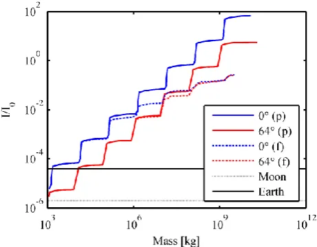
Since it is considered that the value of η experienced by the rover or base will not change with decreased elevation it will be expected that latitude will not greatly effect this scenario directly. There will be some effect on the solar constant fraction due to the increased distance to the latitude band but it is expected this not to be significant. The Pareto fronts for flat and parabolic mirrors for latitudes of 0° and 64° can be seen in Fig. 16. It can be seen that the latitude lines for the same reflector are very similar but it is the higher latitude that experiences the greatest average insolation. This is due to the increased spot size at higher latitudes, due to the larger distance, allowing the target point to spend more time in the spot, offsetting any reduce in intensity. Additionally it can be seen that the parabolic case is again superior to the flat mirror for larger sizes though to a lesser degree in this scenario. This is due to a smaller maximum reflector radius (100km) in comparison to the previous scenario.
[image:9.595.315.541.76.255.2] [image:9.595.48.274.79.372.2] [image:9.595.316.546.540.716.2]For the parabolic case, and for the most challenging insolation increase, the optimised final mass is 3.8x10⁹kg which corresponds to a set of 83 reflectors, each with a radius of 15km, in an orbit with a semi-major axis of 2,600km and eccentricity of 0.14. An alternative option for the parabolic case is to use a smaller reflector with a radius of 660m. The advantage of this scenario over the previous is that a much more feasible reflector size is available, though the final mass of 5.3x10⁹kg is slightly larger, with the main disadvantage being that 61,000 of these reflectors would be required to give the desired average insolation. This would clearly be a large logistical challenge, probably requiring the reflector systems to be manufactured from material processed from the lunar regolith for example, and would require autonomy to be designed into the reflector system. Should one or several of these reflectors fail the effect on the total average insolation will be minimal, in contrast to the use of larger reflectors.
As these systems require an out of plane acceleration component to be offset the amount of propellant mass that must be used for this will now be discussed. The area-to-mass ratios of the reflectors required to maintain the stable orbits are typically small, with the maximum being 0.03m2kg-1. In comparison the two solar sails, IKAROS and NanoSail-D2 launched in 2010, have area-to-mass ratios of 0.63m2kg-1 and 2.5m2kg-1 respectively. Therefore it can be envisaged that the area-to-mass ratio of the reflector system will be much greater than the values calculated here, with low-thrust propulsion being used to a greater extent to stabilise the orbit. Therefore the system masses seen in Fig. 16 will be the maximum initial mass for a single reflector with the majority being a mix of propellant and subsystems.
The minimum and maximum mass fraction of propellant for a period of a lunar month, over the range of orbits, that must be used to reach a range of latitudes for this scenario can be seen in Fig. 17. It can be observed that the minimum value increases steadily with latitude as expected since there will be an increasingly large out-of-plane component. The maximum value, however, decreases above a latitude of approximately 24°. This is because the inner most orbits cannot observe latitudes greater than this and therefore cannot be used. Therefore orbits with larger semi-major axes must be used which have smaller acceleration requirements.
4.3. Moon tracking
[image:10.595.314.544.77.254.2]The results of the Moon tracking scenario can be seen for latitudes of 0° and 64° in Fig. 18. As expected, for the range of masses the average insolation found is greatly improved with many points along the Pareto fronts for the parabolic mirror being greater than the η=0.1 target.
Fig. 17 - Minimum and maximum mass fraction of propellant required to maintain the stability of the orbit from the whole range of orbits for the latitude pointing scenario.
Fig. 18 - Pareto fronts for the flat and parabolic mirrors in the latitude pointing scenario for latitudes of 0° and 64°.
[image:10.595.315.546.299.479.2]mean mass fraction that must be used to maintain the stability of the reflectors orbits over the period of a lunar month is 6x10⁻⁴ for the parabolic case.
Fig. 19 - Insolation provided by a set of 10 reflectors of 3.2km radius averaged over periods of 30 minutes for a parabolic mirror.
For a flat mirror system the system masses are, as anticipated, greater than for the parabolic case. There are again several options for the system with large single mirror applications and larger numbers of smaller mirrors. The large single mirror has a mass requirement of 1.5x10⁸kg which again suggests short periods of very high illumination which is undesirable. The following two minimum mass solutions require large numbers of reflectors. The first of these requires 22,000 reflectors of 200m radius in an orbit of 2,600km semi-major axis and an eccentricity of 0.233 with the second scenarios requiring 2,200 reflectors of 400m radius in an orbit with semi-major axis of 2,000km and eccentricity of 0.061. These are both viable solutions with total system masses of 3.1x10⁸kg and 4.9x10⁸kg respectively. The first of the systems is preferable in terms of nearer-term reflector sizing whilst the second scenario is preferable in general logistical terms due to the order of magnitude less reflectors that must be controlled.
4.4. Displaced polar orbit
The feasibility of the displaced polar orbit scenario shall be determined in a scenario where relatively distant reflectors will attempt to illuminate the point on the Moon furthest along the Sun-line. This scenario has the advantage that all reflectors in the orbit will be able to reflect sunlight simultaneously onto the centre point and therefore to achieve the desired value of η a larger number of smaller reflectors can be used rather than one very larger reflector. This is in contrast to the other scenario where a band with a constant angular distance away from the centre-point is illuminated. In this case the reflector will only have a relatively short time when the target point on the Moon’s surface will fall beneath its ground track. However, due to the large distance of the reflectors that can illuminate the centre point it may well be that a collection of several different reflectors of the second type will be able to provide a greater average illumination.
It can be shown that for the scenario where the reflector is directed at a point along the Sun-line equal to the radius of the Moon that the image seen on the surface will be a half ellipse, with the base at the centre point. This is because the reflectors that can see this point have distances, to the centre of the Moon, rp of greater than 8,500km. Since
the maximum value of rp considered is 10,000km, all the
[image:11.595.45.277.114.288.2]reflectors that can view the centre-point will have small elevation angles, thus creating the elliptical shape of the image. The semi-major axis of the elliptical spot can be found to be less than 300km though the decrease is minimal over the acceptable range of r. The semi-minor axis of the ellipse will, in contrast, increase with r from approximately 37.5km to 45km. Assuming many reflectors are used the insolation will form a large spot in a circular pattern though the intensity will be greatest at the centre. The maximum spread of 300km means that for a target along the equator 11% of the night will be illuminated by the spot. Additionally, due to the low elevation angles it can be assumed that all sides of a cubic lander, with the exception of the bottom face can be illuminated. The number of reflectors to provide an average value for η of 0.1 over the illuminated region can now be found. The overall mass necessary to give a value of η=0.1 over the spot is shown in Fig. 20. The mass is constant regardless of the radius of the reflector but decreases with decreasing distance to the Moon.
Fig. 20 - Total reflector mass required to give an average value for η of 0.1 for the displaced orbit scenario.
[image:11.595.323.537.401.555.2]Fig. 21 - Reflector radius and mass required to illuminate the Cabeus crater at the lunar south pole.
5. NEAR-TERM SCENARIO
All of the scenarios discussed thus far appear to be unfeasible in the near-term, either due to the large mass requirements or other logistical challenges. Many are also only suitable for fairly grand large-scale exploration scenarios and would not be worthwhile for smaller missions such as lunar rovers or other landers or short duration human missions. What will follow is an attempt to provide a near-term solution to the problem of surviving the lunar night by investigating whether a small number of reflectors, on the order of a few hundred metres in radius, can be used to enable survival. This shall be attempted by specifically targeting low orbits under the assumption that the lifetime of the lunar mission which the reflectors must support will be of relatively short duration, i.e. a maximum of several months. This assumption is necessary as low altitude orbits will be perturbed by the harmonics of the lunar gravitational potential and will require larger amounts of propellant to maintain the orbit. As such these low orbits are unfeasible in the long term.
To calculate more accurately whether a mission would be able to survive on the lunar surface the thermal model discussed previously was modified. The key change here is that it is now considered to be any object on the surface, a lander or human exploration vehicle, which will have solar panels that can be used to generate power which can be directly used to generate heat within the vehicle. Additionally, it is assumed that the solar panel area will be greater than area of a single face, as is the case for the Lunette mission which deploys one solar panel per side face. The Lunette mission has a hexagonal side structure and can therefore deploy 6 panels but for the case of this scenario four are assumed. It is also assumed that the top face of the object will not have a solar panel but will receive the full amount of illumination.
The results were calculated using a range of semi-major axes from 1758km to 1938km, eccentricities ranging from 0.005 to 0.1 and reflector radii of 100m to 1,000m. As for
previous scenarios a Pareto front of mass and η was constructed from the results. Using these values of η for the illuminated phases only, the fraction of the night time that can be covered and the reduction in power consumption from the batteries can be calculated. These results are all shown as fractions in Fig. 22 for the case of a single reflector targeting the equator. Also seen are lines showing the first result, along the x-axis, for each size of reflector. So for example all points to the left of the 150m are for reflectors of 100m. For the 250m line this is the only result and for the results greater than this the reflector size grows steadily. It can be seen in Fig. 22 that the lines do not maintain a consistent direction. This is due to the finite nature of the points considered as follows: As the initial points are for small reflectors in distant orbits as these require the lowest mass. As the lines move along the x-axis the reflector orbit decreases in semi-major axis, reducing the coverage of the night time due to the increase in eclipse period discussed previously. When the next size reflector provides a greater value of η for the same reflector mass this it will in general be in a higher orbit, thus it will have a better coverage than the previous reflector.
Fig. 22 - Fraction of; the night time that can be illuminated, the solar constant in the illuminated phases only and the battery capacity that can be saved as a function of reflector mass.
[image:12.595.317.544.333.512.2]Option 1 2 3
Mass 5,100kg 10,300kg 19,400kg
Radius 150m 200m 250m
Night Cover 25% 21.5% 16.4%
Battery charge
(per reflector) 0.35% 0.61% 1.31%
I/I0 0.06 0.16 0.55
a 1776km 1767km 1758km
[image:13.595.39.286.71.195.2]e 0.02 0.01 0.01
Table 2 – Key properties of the two most favourable near-term scenarios.
While these scenarios cannot enable easy survival during the entirety of the lunar night, it is shown that the effective length of the lunar night can be decreased. Using approximately 300 of the smallest reflectors shown in Fig. 22 the effective night time duration can be more than halved. This system would have a mass in excess of 370 tonnes which is still clearly challenging. The total system masses for options 1 to 3 are 367, 371 and 252 tonnes respectively. This shows that there is no advantage of choosing larger reflectors other than decreasing the overall logistical challenge.
6. CONCLUSION
The scenarios presented in this paper show that reflectors can in principle be used to enable the survival of both small and large scale missions on the lunar surface. It has been shown that scenarios exist that allow survivability at high latitudes using the principle of the displaced polar orbit. The lifetime of the forced, precessing ellipse with latitude pointing and tracking type orbits are limited if the target point is offset from the lunar equator due to the need to offset the out-of-plane thrust. The optimum system masses for these two orbits are 5.3x10⁹kg and 1.3x10⁷kg respectively.
For the near-term scenario, where a set of short-lived reflectors in a low orbit are used, the best solution is the use of 300 reflectors of 100m radius which requires a total system mass of 370 tonnes. This system will enable the effective period of the lunar night to be halved. This requirement will be too large to be justifiable for a small lunar lander type mission, but it will greatly increase the capabilities of a short-term human presence on the Moon, increasing the operational duration by 50%. Any increased cost in deploying the reflector system will be offset, in part or completely, by savings made from a reduced total mission lifetime and a reduction in the size of the systems required to survive the night.
The technological challenges of constructing the reflectors is reduced significantly by the undemanding area to mass ratio of less than 1m2/kg. These values are well within current capabilities.
ACKNOWLEDGMENTS
The work report in this paper was funded by the European Research Council through VISIONSPACE (project 227571).
REFERENCES
1. Ulamec, S., J. Biele, and E. Trollope, How to survive a Lunar night. Planetary and Space Science, 2010. 58(14-15): p. 1985-1995.
2. Elliott, J. and L. Alkalai, Lunette: A network of lunar landers for in-situ geophysical science. Acta Astronautica. 68(7-8): p. 1201-1207.
3. Heiken, G.V., D.T. Vaniman, and B.N. French, The Lunar Sourcebook. 1991: Cambridge University Press.
4. Hashimoto, T., et al., Japanese Moon Lander SELENE-2 - Present status in 2010, in IAC. 2010: Prague. p. Japanese Moon Lander SELENE-2 - Present status in 2010.
5. McInnes, C., et al., GEOSAIL: Exploring the Geomagnetic Tail Using a Small Solar Sail. Journal of Spacraft and Rockets, 2001. 38(4): p. 622-629.
6. Ehricke, K.A., Space light: space industrial enhancement of the solar option. Acta Astronautica, 1979. 6(12): p. 1515-1633.
7. McInnes, C., Solar Sailing: Technology, Dynamics and Mission Applications. 2004: Springer Praxis Books.
8. Larson, W.J. and J.R. Wertz, Space Mission Analysis and Design. third ed. Space Technology Library - Space Technology series. 2006: Springer. 9. Christie, R.J., D.W. Plachta, and M.M. Hasan, Transient Thermal Model and Analysis of the Lunar Surface and Regolith for Cryogenic Fluid Storage. 2008, NASA.
10. Fortescue, P.W., J. Stark, and G. Swinerd, Spacecraft Systems Engineering. Third ed. 2003: Wiley.
11. McInnes, C.R., Mars climate engineering using orbiting solar reflectors, in Mars: Prospective Energy and Material Resources. 2010, Springer-Verlag.