Low-cost, multi-agent systems for planetary surface exploration
Giuliano Punzo
Department of Mechanical and Aerospace Engineering, Advanced Space Concept Laboratory, University of Strathclyde, Glasgow, 75 Montrose Street Glasgow, G1 1XJ, UK e-mail: [email protected]
Gordon Dobie
Department of Electrical and Electronic Engineering, Centre for Ultrasonic Engineering, University of Strathclyde 204 George Street Glasgow, G1 1XW, UK e-mai:l [email protected]
Derek J. Bennet
,
Jonathan Jamieson
, and
Malcolm Macdonald
Department of Mechanical and Aerospace Engineering, Advanced Space Concept Laboratory, University of Strathclyde, Glasgow, 75 Montrose Street Glasgow, G1 1XJ
September 12, 2012
Abstract
The use of off-the-shelf consumer electronics combined with top-down design methodologies have made small and inexpensive satellites, such as CubeSats, emerge as viable, low-cost and attractive space-based platforms that enable a range of new and exciting mission scenarios. In addition, to overcome some of the resource limitation issues encountered with these platforms, distributed architectures have emerged to enable complex tasks through the use of multiple low complexity units. The low-cost characteristics of such systems coupled with the distributed architecture allows for an increase in the size of the system beyond what would have been feasible with a monolithic system, hence widening the operational capabilities without significantly increasing the control complexity of the system. These ideas are not new for Earth orbiting devices, but excluding some distributed remote sensing architectures they are yet to be applied for the purpose of planetary exploration. Experience gained through large rovers demonstrates the value of in-situ exploration, which is however limited by the associated high-cost and risk. The loss of a rover can and has happened because of a number of possible failures: besides the hazards directly linked to the launch and journey to the target-body, hard landing and malfunctioning of parts are all threats to the success of the mission.
I. INTRODUCTION
The idea of using small rovers for planetary explo-ration dates back to at least the ’90s [5,7,8,15,16] but the concept of exploiting the cooperative behaviour is much newer and meets the most recent concept of swarm engineering [20]. An important advantage in the exploitation of multiple agents in a distributed fashion, as opposed to centralised monolithic archi-tectures is the possibility of spreading tasks over mul-tiple redundant modules such that a catastrophic fail-ure of one of them does not lead to a mission criti-cal scenario. At the same time each module is usu-ally much simpler than the centralised system it con-tributes to replace, and yet autonomous. All these advantages of decentralised architectures appear to have been now fully understood by the space com-munity for what concerns the orbiting platforms (see for example [13,18]) but, for what concerns rovers for planetary exploration, still the examples are rare. In the late ’90s the JPL implemented the MISUS sim-ulator that reproduced the operations of a team of 3 coordinated scientific rovers through virtual real-ity techniques [4]. More recently JPL provided itself with the hardware able to produce real world tests of cooperating rovers on steep areas [6]. The rovers cooperate in overcoming terrain difficulties helping each-other mobility and are mainly thought to in-crease the level of confidence in the teamed robot sys-tems, highlighting the areas on which the research ef-forts are to be focussed. European industry has been looking instead to more heterogeneous solutions com-posed of rovers, landers and scout robots as in [1, 2]. A feature common to the multi rover systems is the high degree of autonomy required because of the de-lay in communications as different from Earth orbit-ing satellites where connection to ground station can be provided almost continuously.
The target of this work is to frame the possibilities for such architectures to be engineered within lim-ited budgets and relatively inexpensive technology. This is expected to boost limited budget projects where small companies or university students can play their role in the same fashion the successful rev-olution brought by the Cubesat is changing the way of thinking to orbiting platforms. The results of some
experimental tests are reported with the aim to as-sess the capability of displaying mobile sparse phased arrays for soil analysis and data relay. The popu-lar method of artificial potential functions drives the formation shaping while a hierarchical architecture, emerging out of the group behaviour is showed to be functional to the development of the exploration and the data collection. An analysis is carried out to relate the laboratory data to the implementation in a mission like environment, while the actual test in an operational conditions is beyond the scope of this paper. The focal point resides in the possibil-ity of deploying autonomous, mobile and distributed architectures for scientific purposes with a level of technology. This paper develops as follows. Section II. describes the guidance and the control that pro-duces the emergent behavior at the base of the multi agent system. In sections III. and IV. experimental set up and test results are described to be then com-mented and analysed in Section V.. Conclusions and future work are finally reported in Section VI..
II. GUIDANCE AND CONTROL
In this section the theoretical bases of the control scheme that produce an emerging self-arrangement of the rovers are described. The guidance is provided by APF, that, starting from the state of all robot, out-put a desired velocity for each robot independently. The desired velocity changes as function of the sys-tem state. The control properly said is produced by a low level controller (LLC) that outputs the desired turning rates of the wheels. This is defined as lin-ear function of the error with respect to the desired state and makes use of a cosine function to weight the response to the distance error as function of the heading angle, as it will be better explained in section II.III.
II.I Artificial Potential Functions
Morse artificial potential functions, based on pair-wise interactions are used to produced the desired velocity for the system ˙xd = (˙xd,˙yd). These are
at-tractive and repulsive component defined as,
Ua
ij=−Caijexp
−|xij|
Laij
(1)
Ur
ij=Crijexp
−|xij|
Lrij
(2)
with constantsCaij,Crij,Laij andLrij shaping the
formation and its size. Subscriptsij refer to the con-tribution to the velocity field of agent i due to the proximity of agentj; xijis the relative position
vec-tor defined asxi−xj. The desired velocity for any
robotiis obtained as,
˙xd
i =−∇U a i − ∇U
r
i (3)
where,
∇(·) = d(·)
dxi
Uia= X
j
(Uija) U r i =
X
j
(Uijr) (4)
Up to this point, just relative position is used to pro-duce the guidance law. The velocity field can be then modified considering global translational and rota-tional terms. Here just a rotarota-tional one,Hi, is
con-sidered. It is defined as
Hi=H(xi) =krK(xi−X) (5)
where, X is the position of the centre of mass of the formation;Kis a matrix of dimension 2 defined as
"
0 −1
1 0
#
Matrix K produces a component of the desired ve-locity orthogonal to the position vector xi−X of
each agent with respect to the centre of mass of the formation. A general form can include a parameter
krthat tunes the magnitude of the tangential
veloc-ity, but for the purpose of this paper, it was taken unitary. Addition of the rotational term returns a general form of the guidance law as,
˙xd
i =−∇U a i − ∇U
r
i +Hi (6)
II.II Formation shaping
The group of 5 robots controlled through pairwise artificial potential, can arrange in two different clus-ter configurations that correspond to stable equilib-ria. As the formation is obtained regardless the ro-tational term, Equation 3 will be considered in this section. The condition∇Ui = 0 fori= 1,2..,5, that
guarantees equilibrium is satisfied by two possible ar-rangements of the robots. Both a pentagon and a cross formation correspond to critical points of the potential for Caij, Crij, Laij, and Lrij being the
same regardless the pair of agents they refer to. It is possible to exclude pentagon configuration with-out calculating the set of coefficient for each robot. Just by tuning one single parameter Lrij along the
directed edges connecting one agent to the other 4, the pentagon formation is no longer an equilibrium one. The formations pictured in Figure 1 can be anal-ysed considering the gradient of the artificial poten-tial sensed by any of the robots, for instance agent number 1. Given an arrangement of the agents, the first derivative of the artificial potential for any of them in order to define then the conditions that ap-ply to the APF coefficients that produce the agent separation requested. Components of the gradient are calculated in Equations (7) and (8).
∂Ui ∂xi = n X j=1 Caij Laij exp
−|xi−xj| Laij
−Crij Lrij
exp
−|xi−xj| Lrij
xi−xj
|xi−xj| (7)
∂Ui ∂yi = n X j=1 Caij Laij exp
−|xi−xj| Laij
−Crij Lrij
exp
−|xi−xj| Lrij
yi−yj
|xi−xj| (8)
Satisfying the condition Lrij < Laij guarantees the
presence of a minimum (i.e. convexity property) at the equilibrium [9]. Null derivative can be obtained as function ofCrij/Caij ratio. A more detailed
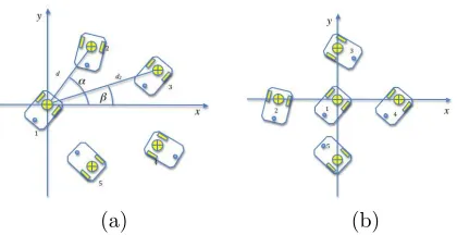
(a) (b)
Figure 1: A formation of 5 agents arranged in (a) pentagon shape due to all to all potential with the same coefficients for all the robots and (b) in a cross shape due to one agent being less ”repulsive” with respect to the others. Attitude is not considered. Formation is defined just by the middle point of the wheel axle becomes ∂U1 ∂x1 pentagon= = 2Ca
La exp − d La
(cosα) + exp
−d2 La (cosβ) −2Cr Lr exp − d Lr
(cosα) + exp
−d2 Lr (cosβ) (9) where,
d2=
d
2
s
tanα+ 1
cosα
2
+ 1 =kd (10)
If the repulsive scale distance considered just for agent 1 shrinks to a value Lr′ such that Lr′ < Lr the pentagon configuration is not an equilibrium one anymore. Indeed taking the derivative of Equation 9 with respect toLr′, this returns
dU1 dx1 pentagon dLr′ = 2
Cr Lr′2
exp − d Lr′ (cosα) + exp −kd Lr′
(cosβ)− d Lr′exp
− d Lr′ (cosα) −kd Lr′exp
−kd Lr′ (cosβ) (11)
that can be proved to be always negative ford > Lr′, or otherwise can be made always negative by set-ting correctly the other parameters of the equation.
This implies that a reduction of the repulsive scale length produces a increase in velocity along the pos-itivex−axis. When this is done for just one robot, this will collapse in the centre of the formation that will rearrange in the cross shape. Moreover as Equa-tions (7) and (8) are linear with respect to Cr. As pointed out previously, the ratioCr/Cacan be used to scale the physical size of the formation.
II.III Low Level Control
The low level controller uses the desired velocity output of APF to provide the rotational speed values for the wheels. This was developed considering the design of the wheeled robots used and is reported for sake of completeness.
The wheel mean speed (WMS) and the wheel speed
difference (WSD)are calculated, for a generic roboti,
as function of the magnitude of the artificial potential derivative and of the error in heading,
W M Si=
|˙xd i|
|∇U∗
i|
Srui W SDi=
∆θi
π Sr (12)
where,Sris the maximum speed value allowed by the
motor in the non-dimensional range [-100; 100], ∆θis the error in heading measured as difference between the desired heading and the actual one,
∆θi=θid−θi θdi =tan−1
˙ yd i ˙ xd i (13)
whileθiis provided by the navigation (tracking)
sys-tem. U∗ is the value of the artificial potential mea-sured at a desired stand-off distance. The function
ui damps the magnitude of the speed commanded to
the wheel in case of large heading error. It is defined as
ui =u(∆θi) =cos ∆θ
i
2
(14)
The actual command to the speed is 2 element vector where the first element is the left wheel speed and the second one is the right wheel speed. It is defined as
ws=
"
W M Si−W SDi/2
W M Si+W SDi/2 #
As the motors used do not output any torque in the interval ]-13;13[ a deadband was set imposing a rota-tional speed corresponding to level 13 for any input in the interval with exclusion of zero. Saturation of the motors can only be partially tackled by the scaling parameterU∗ in Equation II.III that can be consid-ered valid just for the case of 2 robots. When more robots are considered, it potential |∇U∗|is heuristi-cally defined as
|∇U∗
i|= (N−1)
Ca Laexp
−d∗
La
− Cr Lri
exp
−d∗
Lri
(15)
where, d∗ = 500mm is a separation distance be-tween two generic robots, considered isolated, and
N is the number of robots. d∗ is chosen consider-ing twice the maximum distance between axle centre (around which the robot rotates) and the farthest point of the robot chassis from this one. Finally the sensitivity to positioning errors is defined as the er-ror on the magnitude of the artificial potential gra-dient for each agent. Once again in the case of 2 or 3 robots it is relatively easy to scale up the thresh-old on the potential gradient below which the group of robots is considered in a formation, that is, when the potential gradient magnitude is directly related to the error in relative positioning. When there are more than 3 robots, because any possible equilibrium does not produce the same separation between any two robots the computation of the threshold becomes more difficult. For these reasons the tolerance to rel-ative positioning errors, that maps into tolerance on the APF gradient magnitude was heuristically scaled to account for a variable number of robots. The value of the potential threshold was taken as∇U(dd+dtoll)
where,ddis the design distance andδdis the required
precision, or the tolerance.
∆Utoll
i =
N−1 N+ 1
Ca Laexp
−(dd+dtoll) La
−Cr Lri
exp
−(dd+dtoll) Lri
(16)
Moreover an alternative criterion is set to stop the motion of the central rover whose potential derivative is much steeper. This consists into translating the tolerance into the tolerance on the variance of a rover position with respect to the others.
III. FORMATION SHAPING TESTS
The concept proposed of small autonomous and inexpensive rovers for planetary exploration has to be assessed for what concerns the requirements of the hardware and the capability of the intelligence on board to perform the tasks, that here is taken to be the deployment of sensor array. A number of tests were hence performed using five differentially driven wheeled robots moving inside a VICON [19] positioning cell. The scope is to investigate the ca-pability of these simple devices to arrange in a cross shape, assessing their performances in terms of preci-sion positioning and the feasibility of translating the architecture onto more advanced rovers, suitable to operate in a planetary environment.
III.I Hardware setup
The robots used were designed at the Centre for Ultrasonic Engineering and manufactured within the facilities of the University of Strathclyde, they
are shown in Figure 2.b. They are composed of
two differentially driven motors mounted on an aluminium chassis, a ball bearing is used as third
support. They are approximately 175×124×80
(a) (b)
Figure 2: (a) The testbed arena where tests are per-formed, with Vicon T160 cameras. (b) One of the robots used in the tests
to the chassis, these targets are visible in Figure 2.b. In these experiments the robots were driven on the floor of the cell, so only X,Y positions and yaw angle were required to fully characterise the robots position. A more more detailed description of the robotic agents used can be found in [3, 12]. Control actions were defined on the basis of the VICON positional estimate, which was passed directly to the robots SDK. The computer emulated distributed control: inputs were produced for each agent in turn on the basis of its position relative to the others. This ensured that each robot was controlled individually hence any group behaviours emerge out of singles’ actions.
[image:6.595.80.299.127.214.2]The VICON [19] positioning cell is sketched in Figure 2.a.
III.II Software
The guidance and control laws were coded using C# and run on a dual core 2.5 GHz, 2 GB RAM, Windows XP desktop computer rather than on the single robots as previously explained. For conve-nience, the control software, which was written in C#, ran on a host computer that directly controls the wheel speeds of each robot at 40 Hz. The results are fed to the guidance law that determined by the Artificial Potential Functions (APF) that in turn will be fed to the control of the wheel speed as it will be explained in the next section. This is done in turn for each object robot that is considered by the GUI. Robot state, as measured by VICON [19], was
ex-ported to file for post-processing and visualisation in
MATLABR
.
IV. EXPERIMENTAL RESULTS
In this section tests performed are described. The arrangement in a cross formation is tested and outputs for 3 requested positioning distances are illustrated, beside the capability of rotating the formation or switching from a pentagon to a cross formation.
In order to obtain the desired spacing, Equation 7 was solved for Crij/Caij as function of the other
parameters, including the distance amongst the robots, that is considered as design parameter. The same values were used for parameter Laij, for
all (i, j) to calculate Crij/Caij. Lrij parameter
was instead assumed to be the same for all the interactions amongst the robots, except the ones
sensed by one agent. As the testbed labels the
robots consecutively (i.e. from 1 to 5), agent number 1 was given a reduced value for Lrij, that is Lr′.
Values used, for a cross arm of 700 mm are reported in Table 1.
Table 1: Numerical values of coefficients used in nu-merical simulations referred to a cross formation with a 700 mm arm.
Ca Cr La Lr
99.9996 100 700 698
Lr’=69.8
IV.I Precision in Static Positioning
[image:6.595.330.520.479.528.2]by a minimization of the inter agent potential that just depends on relative positions and the final posi-tions with respect to the external reference frame are not assigned, the accuracy in getting a precise po-sitioning must be mapped into a threshold value of the potential gradient sensed by each rover. Results obtained are summarised in Table 2.
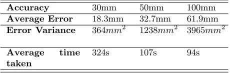
Table 2: Results of the static relative positioning tests for a cross formation with a 700 mm arm.
Accuracy 30mm 50mm 100mm
Average Error 18.3mm 32.7mm 61.9mm
Error Variance 364mm2 1238mm2 3965mm2
Average time
taken
324s 107s 94s
[image:7.595.329.531.130.252.2]The success in the achievement of a static forma-tion is strongly dependent upon the level of accuracy in positioning that is requested. For the 700 mm cross case an accuracy of 20 mm was difficult to ob-tain. Relaxing the requirement to 30 mm acquiring a static formations took on average 324 seconds but this figure shrinks dramatically as soon as the pre-cision requirement is relaxed further. Difficulties in the achievement of very precise positioning are par-tially due to the noise in measurements and the mis-alignment between the centre of the robots perceived by the tracking system and the actual centre about which the robot rotates. Another critical issue was spotted in the frequency at which the system is up-dated. As each command keeps on executing till the new command is fed in, robots may end up passing from an error in positioning on one side to an error on the other side while trying to correct the first one. Moreover, the control frequency scales down with the increase in the number of robots, while the artificial potential field gets richer in local maxima and min-ima. The limited mobility due to the differential drive is another key issue to account for when considering the capabilities of the system to quickly achieve a precise configuration. Beside it was noted how, de-spite the cosine term in the low level control function, the final equilibrium position was missed several time
Figure 3: Trajectories followed by the 5 agents while arranging in a pentagon formation first (stars) and then in a cross formation (circles).
when the rovers were committed to sharp bends in the final approach to the equilibrium positions. The deadband of the actuators, that is, the lower bound on the available spinning rate of the wheel, was found to contribute significantly, in negative sense, to this behaviour.
IV.II Formation Switching
In the formation switching tests a group of 5 robots randomly deployed in the test area at the beginning of the test acquires the pentagon formation described, then, theLr parameter is manually switched toLr′ through the GUI for the agent that the system la-beled as nr 1. This collapses into the centre forcing the others to adjust their distance accordingly. The two formations are pictured in Figures 3 and 4.
IV.III Rotating Formation
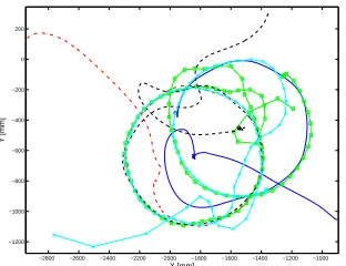
The rotating formation was tested starting from a random arrangement and both including the rota-tion since the beginning of the test, and switching the rotational term on when the formation was already stabilised in a cross shape. Just the cross shape was tested although, in theory, nothing would prevent the pentagon formation to undergo rotation by the same means. Results obtained are illustrated in Figures 5
[image:7.595.72.302.257.330.2](a) (b)
Figure 4: A formation of 5 agents arranged in (a) pentagon formation and then (b) in cross formation
−2800 −2600 −2400 −2200 −2000 −1800 −1600 −1400 −1200 −1000
−1200 −1000 −800 −600 −400 −200 0 200
X [mm]
Y [mm]
Figure 5: Trajectories followed by the 5 agents while arranging in a cross formation and rotating about its centre. The loss of one agent doesn’t produce catas-trophic consequences as the rovers rearrange around a new central one keeping on exhibitihng the rota-tional behaviour.
[image:8.595.78.295.166.288.2](a) (b)
Figure 6: A formation of 5 agents arranged in (a) four point star and (b) in a three point star that excludes an agent with a failure
rotating formation do not overlap exactly the maxi-mum distance between 2 trajectories is always below 40 mm.
The loss of one agent was simulated as well in this context. When this happens agents are sorted again and the one withLrij=Lr′is identified always as the
corresponding to the first sorted agent. The forma-tion will then rotate about the new leader. Indeed no robot is really leading the formation as all the robots rotate about the centre of mass of the formation; but in the cross formation, as well as in a three point star formation, the central robot is in the centre of mass, hence all the others rotate about the first one. This confirms that the emergence of a central symmetry is not dependent upon the number of agents involved. It is the equilibrium configuration that robotic agents achieve to compensate for the asymmetry of the po-tential with respect to one agent.
V. DISCUSSION
[image:8.595.119.275.420.540.2]Multiple versus Single Rovers
In general the paradigm shifting from single vehi-cle to multiple ones carries a number of advantages for the design of the system.
The system is robust to failure and scalable, that is, allowing a certain degree of redundancy for the scientific payload, the occurrence of a failure making one of the rovers unavailable does not affect the possibilities of achieving the scientific goals of the mission. Experimental data confirm that a given behaviour keeps on being operated also in case of loss of one agent. This also allows to exclude or kill robots partially damaged without compromising the mission success.
The single units can be more robust per
se than a larger traditional rover from a structural
point of view. This comes as consequence of the
reduced dimensions that implies less critical points
from the structural point of view. Moreover the
smaller inertia of each rover makes possible to relax the requirements on the acceleration during the launch and the landing, leading to an advantage for the design of the whole mission and its costs.
Expendable rovers do not need double
redundancy even for key components such as
the mobility subsystem whereas it is needed for traditional surface exploration systems. This is the main reason that led to the popular 6 wheel
design. Simpler designs can hence be considered
with consequence saving in terms of weight with respect to a scaled version of a traditional rover.
Smaller rovers may be designed to be less energy demandingas a consequence of the weight saving, the lighter redundancy requirements and, in general, the smaller number of subsystems to operate, with respect to a scaled version of the tra-ditional rovers. This is expected to reduce the total power budget of the exploration system although deeper analysis would be required to assess this.
Advantages of Swarming techniques
Swarming techniques and decentralised control systems (that can also suggest a parallel decen-tralised mission management system) as the one described in this work are able to boost the perfor-mance of the exploration system while keeping its complexity level low.
In particular the emergence of a central
symmetry geometry out of the self arrangement of the rovers elect a natural leader in the centre of the formation, that can be in charge of some specific tasks such as the path planning for the motion of the whole formation, as well as other functions that may require an higher hierarchical level.
The system behaves as a single cohesive group, that is the exploration task is not pursued by the single units leading to a dispersion of the efforts. The units collaborate to the achievement of a global task taking advantage of sharing their capabilities that can hence be of heterogeneous kind. The group capabilities scale up with the number of components while keeping the control complexity constant. At the same time, even the loss of some rovers does not diminish catastrophically the system performances.
Some tasks can benefit from the formation shaping: in particular data relay can be performed by phasing antenna elements on each rover [14] and wide based stereoscopic vision can be achieved using cameras on different rovers [10]. In general differential measurements can be easily taken to aid either navigation or as part of the scientific targets of the exploration.
The low cost approach
The use of off-the-shelf, non space qualified equip-ment adds on a number of appealing features to the multi rover system. This is made possible by the increased overall robustness to failure given by the number of units involved. One main advantage is
represented by the dramatic reduction of costs
associated to the choice of equipment. Moreover
tech-niques is available for such components making the programming task lighter and easily accessible for external contributors.
The cheapest components involved allow more
subjects to develop planetary exploration mission concepts, that is expected to give rise to better solutions. Moreover establishing concurrency can produce benefits to the technological development of the space exploration and the spin off of concept for everyday life.
Finally off the shelf components can attract subjects such as universities, research institutions,
small companies, and other subjects normally
operating on markets other than space. This
widen the spectrum of subjects working in the exploration releasing space agencies from some of the design and production duties, while possibly improving the processes.
Towards practical implementation
The performance of the multi-rover system high-lighted by the experimental tests should be regarded considering a number of key factors that make the system tested quite different from a prospective one to deploy in a planetary exploration mission.
The tests reported here rely on the presence of an external tracking system, that is able to give an orientation to the formation by setting up an external reference frame. This is not the case of operations in a real environment where all the rovers must be equipped with navigation sensors. Moreover the pos-sibility of not being able to track all the rovers state continuously is to be accounted. The guidance law described here just depends upon relative position-ing makposition-ing the need of knowposition-ing the positions of the agent with respect to an external reference frame not necessary. For what concerns the on board instru-mentation, this work does not provide an estimation of the performances achievable by the system. This is one of the development direction for the future work. For what concerns the possibility ofexploring the environmentby moving to different places, this can be associated with the navigation of one single agent as well as the capability of orienting the system with
respect to the external environment. Say this task is accomplished by the central rover, just relative posi-tioning and orientation is then required by any rover other than the central one.
The construction accuracy of the robots is
sometimes responsible for the long time required to get a final position as the misalignment of the body reference frame with respect to the centre of rota-tion produces an unwanted translarota-tion for any com-manded pure rotation of the rovers. This is of course improvable but is something to take into account when thinking to a system designed and built through a process other than the ones used nowadays for such devices.
The simple design based ontwo wheeled and dif-ferential steeringis not suitable for anything other than a planar surface. In any case it contribute to produce a conservative assessment of the motion ca-pabilities of the swarming rovers.
The central computations of the control law keeps the asynchronous characteristics of a dis-tributed system but lowers its operating frequency. Indeed the central computer has to provide the con-trol inputs for each robot at turn. Although the computer where the computations were run has more computational power than the embedded micro com-puters the tested rovers are equipped with, the fact that it is not a dedicated hardware (i.e. an it has an operative system that runs other functions beside the control ones) and that it has to account for 5 robots can be seen as another conservative way of assessing system characteristics.
also in experimental environment in future works. Finally, concerns may arise because of the tough conditions that are usually found in extrater-restrial environments, while in this paper just the case of rovers moving on a plane is considered. Nonetheless the experiments presented here aim to be inspirational for what is possible to achieve with a multi agent rover system designed for space explo-ration.
VI. CONCLUSIONS AND FUTURE WORK
In this work it was shown how relatively inexpen-sive hardware can be used to make rover-like vehi-cle to perform cooperative tasks autonomously. This suggests that there is a potential for the development of low cost multi agent rover systems for exploration purposes. Argumentations have been taken to show how, with a relatively simple and cost effective equip-ment, a multi micro rover mission can be designed within limited budgets. The simplifications intro-duced into the system such as the external tracking or the centralised computing are expected to balance out, at least partially, their positive and negative ef-fects on the system performances. The centralised computing is indeed diminishing the system perfor-mances while the external tracking provides more ac-curate data than the one obtainable through on board sensing. Problems such as mobility or compliance with the environment characteristics were not faced here as a general approach was taken. Particulariza-tion for a specific mission or environment concerns single rovers while this work looks at the possibility of a rover formation deployment.
A main contribution given by the present work can be spotted into the experimental validation of one par-ticular emergent behaviour, that is the collapse of a given formation into a central symmetry one by non symmetric changes in the guidance potential. Test-ing similar behaviour in a not fully connected system is the next step for this research.
The costs of a space exploration mission connected to the launch and transfer phases are not lowered by the approach presented, hence a strict parallel with low cost satellites is not appropriate. Nevertheless
the results presented suggest the possibility of open-ing the planetary exploration to piggy-back projects, or complimenting the existing high-value assets by adding capabilities typical of swarming systems.
REFERENCES
[1] F. Cordes, I. Ahrns, S. Bartsch, T. Birnschein, A. Dettmann, S.e Estable, S. Haase, J. Hill-jegerdes, D. Koebel, S. Planthaber, T. Roehr,
M. Scheper, and F. Kirchner. Lunares:
lu-nar crater exploration with heterogeneous multi robot systems. Intelligent Service Robotics, 4:61–89, 2011.
[2] F. Cordes, S. Planthaber, I. Ahrns, T. Birn-schein, S. Bartsch, and F. Kirchner. Cooperat-ing reconfigurable robots for autonomous plan-etary sample return missions. InReconfigurable Mechanisms and Robots, 2009. ReMAR 2009.
ASME/IFToMM International Conference on,
pages 665 –673, june 2009.
[3] G.I. Dobie. Ultrasonic Sensor Platforms for
Non-Destructive Testing. PhD thesis, University
of Strathclyde, 2010.
[4] T. Estlin, A. Gray, T. Mann, G. Rabideau, R. Casta˜no, S. Chien, and E. Mjolsness. An integrated system for multi-rover scientific
ex-ploration. In Proceedings of the sixteenth
national conference on Artificial intelligence,
AAAI ’99/IAAI ’99, pages 613–620, Menlo Park, CA, USA, 1999. American Association for Arti-ficial Intelligence.
[5] S. Hayati, R. Volpe, P. Backes, J. Balaram, and R. Welch. Microrover research for exploration of mars. InUniversity of Wisconsin, pages 1–2, 1996.
[7] M. Lauria, F. Conti, P.-A. Musli, M. van Win-nendael, R. Bertrand, and R. Siegwart. Design and Control of an Innovative Micro-Rover. 1998.
[8] J. Matijevic. Mars pathfinder microrover - im-plementing a low cost planetary mission experi-ment.
[9] C.R. McInnes. Vortex formation in swarms of interacting particles. Physical Review E
(Sta-tistical, Nonlinear, and Soft Matter Physics),
75(3):032904, 2007.
[10] C.F. Olson, H. Abi-Rached, Ming Ye, and J.P. Hendrich. Wide-baseline stereo vision for mars rovers. InIntelligent Robots and Systems, 2003. (IROS 2003). Proceedings. 2003 IEEE/RSJ
In-ternational Conference on, volume 2, pages 1302
– 1307 vol.2, oct. 2003.
[11] D. Pais, Ming Cao, and N.E. Leonard. For-mation shape and orientation control using pro-jected collinear tensegrity structures. In
Ameri-can Control Conference, 2009. ACC ’09., pages
610 –615, June 2009.
[12] S.G. Pierce, k. Worden, R. Summan, G. Dobie, and J.J. Hensman. Towards implementation of reconfigurable robotic strategies for structural health monitoring. In 5th European Workshop
on Structural Health Monitoring EWSHM, pages
610 –615, Sorrento, Italy, July 2010.
[13] C. Pinciroli, M. Birattari, E. Tuci, M. Dorigo, M. Rey Zapatero, T. Vinko, and D. Izzo. Lattice formation in space for a swarm of pico satellites.
In Proceedings of the 6th international
confer-ence on Ant Colony Optimization and Swarm
Intelligence, ANTS ’08, pages 347–354, Berlin,
Heidelberg, 2008. Springer-Verlag.
[14] G. Punzo, D.J. Bennet, and M. Macdonald. A fractally fractionated spacecraft. In IAC 2011,
3-7 October 2011, Cape Town, SA, 2011.
[15] R. Siegwart, M. Lauria, P. Mausli, and
M. Van Winnendael. Design and implementa-tion of an innovative micro-rover. pages 181 – 187, Albuquerque, NM, USA, 1998.
[16] G. Skelton and Q. Pang. Hierarchical architec-ture for a multi-rover system. pages 346 – 350, Huntsville, AL, United states, 2008.
[17] H. G. Tanner, A. Jadbabaie, and G. J. Pappas. Flocking in fixed and switching networks.
Auto-matic Control, IEEE Transactions on, 52(5):863
–868, may 2007.
[18] H. Tripp and P. Palmer. Stigmergy based be-havioural coordination for satellite clusters.Acta
Astronautica, 66(78):1052 – 1071, 2010.
[19] http://www.vicon.com/products/t160.html Vi-con T160 website, 2012.
[20] A. F. T. Winfield, C. Harper, and J. Nembrini. Towards dependable swarms and a new disci-pline of swarm engineering. In SAB 2004 In-ternational Workshop, July 17, 2004 - July 17,
2004, volume 3342 of Lecture Notes in
Com-puter Science, pages 126–142, Santa Monica,