Space Reflectors using Distributed Solar Pressure
A Borggr¨afe1, J Heiligers1, M Ceriotti2 and C R McInnes1
1Department of Mechanical and Aerospace Engineering, University of Strathclyde,
Glasgow G1 1XJ, United Kingdom
2School of Engineering, University of Glasgow, Glasgow G12 8QQ, United Kingdom
E-mail: [email protected]
Abstract. This paper investigates controlled elastic deflection of thin circular space reflectors using an inverse problem approach to non-linear thin membrane theory. When changing the surface reflectivity across the membrane, the distributed loads due to ambient solar radiation pressure can be manipulated optically, thus controlling the surface shape without using mechanical or piezo-electric systems. The surface reflectivity can in principle be modulated using uniformly distributed thin-film electro-chromic coatings. We present an analytic solution to the inverse problem of finding the necessary reflectivity distribution that creates a specific membrane deflection, for example that of a parabolic reflector. Importantly, the reflectivity distribution across the surface is found to be independent of membrane size, thickness and solar distance, enabling engineering of the reflectivity distribution directly during the manufacture of the membrane.
1. Introduction
Large and lightweight flexible membrane structures pose an interesting concept for many future space-based applications such as communication antennae [1], scientific telescopes [2], solar power satellites [3] and solar sail propulsion [4]. Deploying a high-reflective parabolic membrane in space enables any of these applications. However, it is essential to keep the system mass as low as possible to reduce launch costs, while at the same time providing controllability, reliability and accuracy of the surface shape in the space environment. To this aim, we consider controlling the membrane shape through ambient solar radiation pressure (SRP) acting on the structure in space. Although being relatively small in magnitude, about 10µN/m2 at the Earth’s distance from the Sun, SRP has already been used successfully for passive attitude control of satellites [5] and for continuous propulsion of solar sail spacecraft [6]. Since the aperture size of a space reflector is expected to be in the order of 100 m in diameter, for example, to maximise spatial resolution or antenna gain, light pressure applies a reasonable force sufficient to deflect a thin reflective film. However, it will be shown in this paper that the nominal deflected profile of the membrane due to uniform SRP loads is in fact non-parabolic in shape. Since only a parabolic surface can focus electro-magnetic radiation into a single point, in order to realise the proposed applications of antennae, telescopes and solar power collection, the light pressure distribution has to be modulated across the membrane.
The force exerted on a surface by solar photon momentum essentially depends on the reflectivity coefficient of the material [4]. The higher the reflectivity the higher the total force, since fewer photons are absorbed or diffusely scattered by the material. The surface reflectivity can in principle be modified using thin-film electro-chromic coatings, which consist of an electro-active material that changes its reflectivity according to an applied electric charge [7], or by engineering a reflectivity distribution directly during the manufacture of the membrane. Thin-film liquid crystal devices have already been employed successfully for attitude control on the first solar sail in space, IKAROS (Japan), in 2010 [6]. When modulating the reflectivity, non-uniform SRP loads can be generated for controlled membrane deflection without using additional mechanical or piezo-electric control actuators, as for example shown in [8].
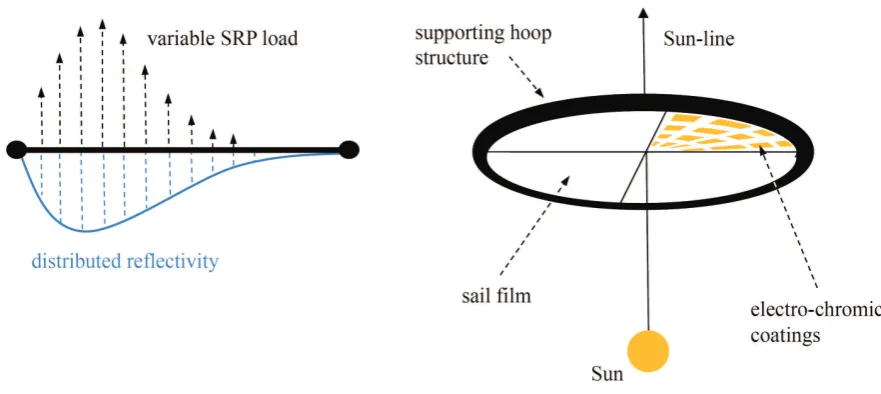
Figure 1. Schematic of circular space membrane reflector with thin-film electro-chromic coatings uniformly distributed across the surface to modulate light pressure load (left) and supporting rigid hoop structure (right).
required reflectivity distribution can be calculated by formulating an inverse problem (section 4.1). Resulting paraboloid-type deflection shapes and deflection magnitudes will be evaluated in section 5 in terms of the achievable focal lengths as function of aperture radius and solar distance.
2. Membrane deflection using variable solar pressure loads
The reflector is modelled using a thin polyimide Kapton film, a material likely to be used for future space membrane structures due to its high resistance to extreme temperatures and radiation [10]. The membrane is supported by a circumferential hoop structure, forming hinged-support type boundary conditions at the edges. The SRP loads are calculated using a simplified SRP model [4]. It assumes that the membrane surface is a perfectly (specular) reflecting mirror, such that the resulting SRP force is always perpendicular to the surface. Therefore, the model neglects all other forms of optical interactions between the solar photons and the material such as scattering, absorption and thermal re-emission. In particular, a real surface would absorb a fraction of the photons and emit the energy as thermal radiation, creating an additional in-plane transversal force component due to non-ideal reflectivity. The model also does not account for wrinkles, and thus assumes a perfectly flat surface. Accordingly, the solar radiation pressure pSRP can be written as
pSRP =p0[1 +ρ(r)]
RS,0 RS
2
at a radial distance RS from the Sun, with the pitch angle α between the Sun-reflector line and the surface normal, and p0 = 4.563×10⁻⁶N/m2 the light pressure at RS,0 = 1 AU = 149,597,871 km (Astronomical Unit). Prior to deflection, the membrane surface is assumed to be perpendicular to the Sun-reflector line, thus α = 0. Electro-chromic thin-film coatings are further assumed to be uniformly distributed across the surface, as shown schematically in figure 1, while neglecting the additional mass and thickness that would be introduced to the membrane. Ideally, these coatings are capable of modulating the surface reflectivity ρ in the interval 0≤ρ ≤1. When now assuming that the membrane reflectivity is no longer constant, but changes across the surface, the local SRP becomes a function of reflectivity ρ(r) at the radial position r from the centre of the membrane. In here, ρ(r) = 1 represents a perfectly reflecting mirror that experiences the maximum possible SRP pSRP,max = 2p0, while ρ = 0 reduces the effective SRP load topSRP,max/2 =p0, because (ideally) no photons are reflected and only the momentum of the incoming photons applies a force to the surface. Consequently, the induced light pressure forces can be modified directly when changing the surface reflectivity.
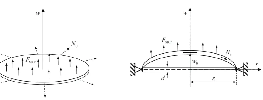
In the present analysis, only the static structural bending of the membrane is accounted for, ignoring any dynamical response (e.g. vibrational modes) of the real structure due to time-dependent loads, movements of the structure or flexibilities in the supporting hoop. A thin circular isotropic membrane of radius R and thickness d under uniform vertical SRP load FSRP, created by the solar radiation pressure pSRP, is shown in figure 2. Due to the very small thickness and relatively large deflections w (i.e. a high W = w/d ratio), non-linear theory of circular membranes needs to be considered. In general, thin membrane-like structures offer a very small flexural rigidity and therefore cannot resist bending loads [11]. Furthermore, radial and transversal in-plane tensions are non-negligible, while for lowW ratios, they are usually ignored within the well-known linear beam theory [12]. The symmetrical out-of-plane deflection can be described by a second-order non-linear coupled system, according to [13, 14], as
d3w dr3 +
1 r
d2w dr2 −
1 r2
dw dr −
N0 D
dw dr −
˜ Nr
D dw
dr = pSRPr
2D (2)
d ˜Nr dr +
˜ Nr−N˜θ
r = 0 (3)
d ˜Nθ dr −
˜ Nr−N˜θ
r + Ed 2r dw dr 2
= 0 (4)
with the radial and tangential in-plane tensions Nr and Nθ and the initial in-plane tension N0 at the edges. Further, using the Young’s modulus E, Poisson ratio ν and flexural rigidityD of the membrane material
D= Ed
3
Figure 2. Circular reflective membrane under uniform vertical SRP load and initial in-plane tension (left), and membrane cross-section with hinged-edge support and deflected shape (right).
After being initially stretched by the load N0 (see figure 2), the membrane is then subjected to the vertical SRP load due to pSRP. Therefore, the in-plane loads are decomposed as follows
Nr=N0+ ˜Nr and Nθ =N0+ ˜Nθ (6)
where ˜Nr and ˜Nθ are incremental changes fromN0 due to the SRP load. The system in equations (2)-(4) can further be written in non-dimensional form as
¨ θ+ θ˙
ξ −(k 2+ 1
ξ2)θ−12(1−ν 2)S
rθ = 6(1−ν2)PSRPξ (7)
˙ Sr+
Sr−Sθ
ξ = 0 (8)
˙ Sθ−
Sr−Sθ
ξ =−
1 2ξθ
2
(9)
where the following non-dimensional variables are used
ξ= r
R, (˙) = d
dξ, W = w
d (10)
θ= dW dξ =
R d
dw
dr, Sr= ˜ NrR2
Ed3 (11)
and after introducing the initial tension parameter k and the loading parameter PSRP
k=
r
N0R2
D and PSRP =
pSRPR4
Ed4 (12)
ξ2θ¨+ξθ˙−[1 +ξ2(k2+ 12(1−ν2)Sr)]θ = 6(1−ν2)PSRPξ3 (13)
ξ2S¨r+ 3ξS˙r =−
θ2
2 (14)
Within the scope of this paper, no initial in-plane tension is accounted for to maximize the deflection, so the parameterk is zero. The corresponding boundary conditions (BC) to solve the boundary value problem (BVP) for hinged edge support are then
θ= 0 Sr= 0
)
forξ= 0 and ˙ θ¨= 0
Sr+ (1−ν)Sr= 0
)
forξ= 1 (15)
This type of support was chosen to represent the real conditions in the best way, since the (approximately rigid) hoop structure inhibits membrane deflections in the u direction, but allows for a non-zero slope dW/dξ at the edges.
In principle, the above BVP can be solved for any radial-symmetric load distribution PSRP(ξ) [11]. Later, in section 4, variable load distributions will be used to change the nominal deflection curves of membranes subjected to uniform pressure loads [14]. After the BVP has been solved forθ(ξ), the relative membrane deflection is obtained through
W = w d =
Z
θdξ (16)
The BVP is solved numerically with the MATLAB ’bvp4c’ routine, using the three-stage Lobatto IIIa collocation method [15]. The implementation was validated using the results observed in [14] for Silicon Nitride membranes with clamped-edge support under uniform vertical load, showing that the deflections found and non-dimensional in-plane tensionsSr(ξ) could be reproduced (results not included here). Furthermore, the chosen approach was validated with a numerical finite-element analysis (FEM) conducted in [16], using circular polyester Mylar films (density ρ= 1350 kg/m3,E = 3.5×10⁹N/m2, ν = 0.38 and dMylar = 1.0×10⁻⁶ m) of varying radius subjected to uniform vertical light pressure at the Earth’s distance from the Sun (1 AU). Figure 3 shows the relative out-of-plane deflections obtained when solving the coupled ODE system for uniform SRP load for the same conditions. The central deflections are in the order of 0.2% of the membrane radius and in good agreement with the results found in [16]. According to the reference, the variation of SRP magnitude due to the local deflection of the film was also taken into account. The film deflection changes the local light incidence angle, cf. pitch angle α in equation (1), reducing the nominal SRP load. However, comparing the results in figure 3 with [16] indicates that this effect is negligible, due to very small angular deflections of the surface.
3. Nominal membrane deflection for constant reflectivity
0 0.1 0.2 0.3 0.4 0.5 0.6 0.7 0.8 0.9 1 0
0.0005 0.001 0.0015 0.002 0.0025 0.003
ξ = r/R
w/R
[image:7.595.76.517.97.339.2]R = 1 m R = 5 m R = 10 m R = 25 m
Figure 3. Reproduction of relative out-of-plane deflection for Mylar films (d= 1µm) at Earth distance from the Sun (1 AU) for different membrane radii, found in [16].
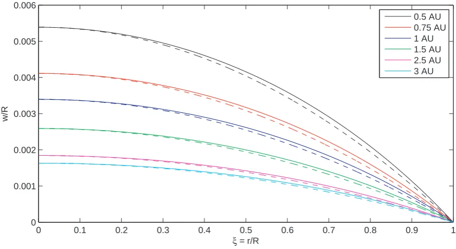
the deflection properties of a Kapton membrane (d= 2.5×10⁻⁶m, ρ= 1572 kg/m3, E = 2.48× 10⁹N/m2 and ν = 0.34 [17]) are investigated in the following. Figures 4 and 5 show the relative membrane deflections obtained for different membrane radii R = 1,5,10,25,50 and 100 m and for solar distances RS = 0.5,0.75,1.0,1.5,2.5 and 3.0 AU, using a 100 m radius membrane. The dashed lines for each case indicate hypo-thetical parabolic reference curves that are satisfying the same boundary conditions and the same central deflection. As can be seen, the deflection surfaces obtained are clearly not ideal paraboloids, as will be discussed below. The central deflections increase for larger membrane sizes and smaller solar distances, as expected. In general, all absolute deflections stay below 0.6 m, even for relatively large membranes (100 m radius) and close to the Sun (0.5 AU). This already indicates large focal distances when using the membrane as a solar power collector or antenna. The achievable focal distances will be discussed in section 5. The maximum radial membrane stress is found to be σmax =Nr,c/d= 7.595 ×10⁴N/m2 at the centre for a membrane radius of R= 100 m at 0.5 AU. Compared to the ultimate tensile strength of Kapton, which is σlim = 2.31×10⁸N/m2(at 23◦Celsius) and 1.39×10⁸N/m2(at 200◦Celsius), the maximum stresses never exceed 0.05 % of the limit load case. This indicates that even much thinner membranes could be employed for future space membrane reflectors.
0 0.1 0.2 0.3 0.4 0.5 0.6 0.7 0.8 0.9 1 0
0.0005 0.001 0.0015 0.002 0.0025 0.003 0.0035
ξ = r/R
w/R
[image:8.595.75.519.96.336.2]R = 1 m R = 5 m R = 10 m R = 25 m R = 50 m R = 100 m
Figure 4. Relative out-of-plane deflection for Kapton membrane (d = 2.5µm) at Earth distance from the Sun (1 AU) for different membrane radii (solid lines) and hypothetic parabolic reference curves (dashed lines).
0 0.1 0.2 0.3 0.4 0.5 0.6 0.7 0.8 0.9 1
0 0.001 0.002 0.003 0.004 0.005 0.006
ξ = r/R
w/R
0.5 AU 0.75 AU 1 AU 1.5 AU 2.5 AU 3 AU
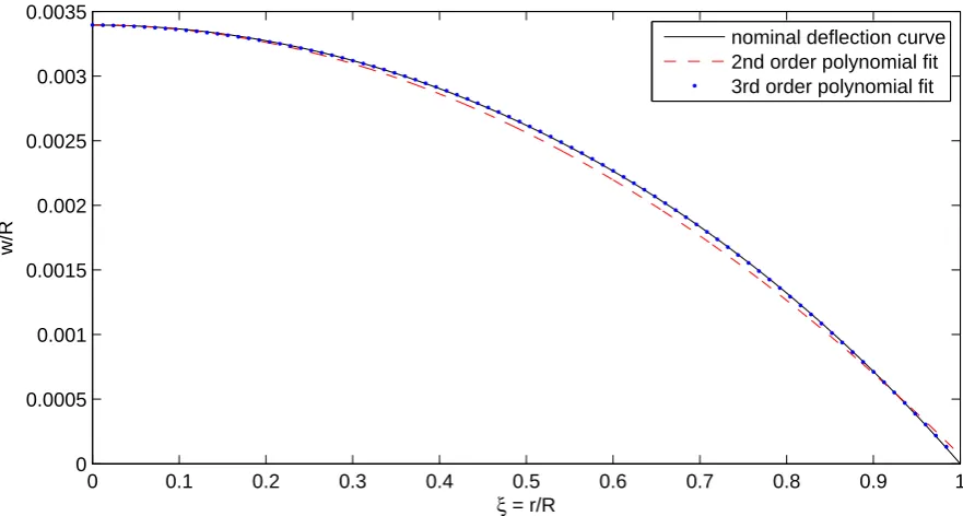
[image:8.595.73.517.465.708.2]0 0.1 0.2 0.3 0.4 0.5 0.6 0.7 0.8 0.9 1 0
0.0005 0.001 0.0015 0.002 0.0025 0.003 0.0035
ξ = r/R
w/R
[image:9.595.75.516.98.334.2]nominal deflection curve 2nd order polynomial fit 3rd order polynomial fit
Figure 6. Nominal deflection curve for uniform load using Kapton membrane (R= 100 m, d= 2.5µm) at 1 AU (black line), and second and third-order polynomial fits, constrained to central deflection valuew0/R.
valuew0/R. The cubic fit (dotted blue line) is almost identical with the deflection curve (solid black line). Although the parabolic fit (dashed red line) does not match the BC at the edges exactly, it represents a better second-order fit than the parabolic reference curves used in figures 4 and 5.
The deviation of the membrane deflection curve from the ideal parabolic shape is most visible in the mid-region of the membrane. Here, the local gradient dw/dξ is smaller than the gradient of the parabola and vice-versa close to the edges. This indicates that the Kapton surface will not concentrate incoming light (or other forms of electro-magnetic radiation) into a single focal point due to aberration. In particular, the cubic surface reflects incoming light at the mid-part towards higher focal lengths and vice-versa for light impinging close to the edges. In the following, it will be shown that the cubic deflection can be corrected to a true parabolic one using uniformly distributed reflectivity across the membrane surface.
4. Surface control using variable reflectivity distribution
represents the SRP load distribution. Solving equation (1) for ρ(ξ) results in
ρ(ξ) = pSRP(ξ) p0
RS,0 RS
−2
−1 (17)
where an arbitrary load functionpSRP(ξ) can be used, as long as the physical constraint for ρ(ξ) ∈[0,1] is satisfied. This property is now used to control the membrane shape, neglecting again the additional mass and thickness that would be introduced to the membrane when distributing an electro-chromic coating layer on the surface, although a static reflectivity distribution could also be engineered during the manufacture of the membrane with no mass penalty.
ConnectingpSRP(ξ) with the non-dimensional load parameter PSRPin equation (12) such that
PSRP(ξ) =
pSRP(ξ)R4
Ed4 (18)
and substituting for the uniform load distributionPSRPwithin the coupled ODE system, equation (13), introduces an arbitrary (radial symmetric) load function into the system that can be solved as a BVP, with corresponding boundary conditions at the center and at the edges.
4.1. Inverse problem approach for given membrane deflection shape
An inverse problem can now also be formulated, which is defined as calculating the necessary reflectivity function ρ(ξ) to obtain a given membrane deflection shape W(ξ). This can be, for example, a parabolic shape in order to use the membrane as a large antenna, telescope or solar power satellite. A parabolic deflection curve, as used already in figures 4 and 5, is of the general form
Wparab(ξ) = −Aξ2+Bξ+C (19)
The coefficient A is the slope and C is the vertex of the parabola. The parameter B is zero, thus WP(ξ) has no horizontal offset from the symmetry axis, which could only be created through an asymmetric load. When inserting the ideal parabolic curve into the coupled ODE system, it can be solved for PSRP(ξ) in order to obtain the load distribution necessary to create this curve. Rearranging equation (13) for PSRP(ξ) and equation (14) for the non-dimensional in-plane tension Sr(ξ) gives
PSRP(ξ) = 1 ν∗
" ...
W ξ +
... W
ξ2 −[1 +ξ
2(k2+ 2ν∗
Sr)] ˙ W
ξ3
#
(20)
¨ Sr =−
3 ξ ˙ Sr−
1 2ξ2( ˙W)
2 (21)
using the Poisson parameter ν∗ = 1−ν2. Inserting the parabolic curve W
parab(ξ) for W, the above equations now become
¨ Sr =−
3
ξS˙r−2A
2 (23)
Equation (23) can be solved in general for Sr, without specifying boundary conditions
Sr =− 1 4A
2ξ2− C1
2ξ2 +C2 (24)
When again using the boundary conditions for hinged edge support, equation (15), the above equation becomes
Sr =− 1 4A
2ξ2+1 4
3−ν 1−νA
2 (25)
Inserting into equation (22), the load distribution associated with a general parabolic deflection curve can now be written as
PSRP(ξ) = −A3ξ2+ 3−ν 1−νA
3 (26)
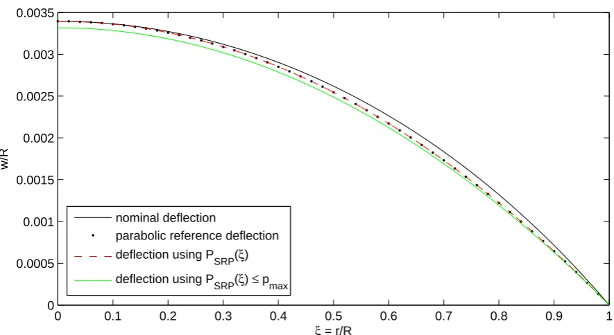
which shows that PSRP(ξ) is fully determined by the polynomial coefficient A and ν. The inverse problem is now applied to create a parabolic deflection shape for a 100 m Kapton membrane of thickness 2.5µm at the Earth’s distance from the Sun. Figure 7 shows the nominal cubic deflection for constant reflectivity, thus a uniform load distribution. A parabolic reference deflection curve (dotted black line) is taken as input for the inverse problem. In order to match the central deflection of the nominal cubic deflection curve (figure 4) and the zero-deflection boundary condition at the edge, the coefficients are chosen to beA=C =W0,nom, whereW0,nom represents the nominal central deflection obtained for constant reflectivity. Accordingly, the parabolic reference curve is now
WP(ξ) = −W0,nomξ2+W0,nom (27)
After inserting into equation (26), the light pressure distribution becomes
PSRP(ξ) = W03,nom
3−ν 1−ν −ξ
2
(28)
After introducing this function into the coupled ODE system, it can be solved as a regular BVP. As can be seen in figure 7, the resulting deflection curve (dashed red line) exactly matches the input curve.
When reformulating equation (28), the absolute SRP load distribution can be written as
pSRP(ξ) = Ed4
R4 W 3 0,nom
3−ν 1−ν −ξ
2
(29)
0 0.1 0.2 0.3 0.4 0.5 0.6 0.7 0.8 0.9 1 0
0.0005 0.001 0.0015 0.002 0.0025 0.003 0.0035
ξ = r/R
w/R
nominal deflection
parabolic reference deflection
deflection using P SRP(ξ)
deflection using P
[image:12.595.75.518.94.336.2]SRP(ξ) ≤ pmax
Figure 7. Nominal deflection curve for uniform load using Kapton membrane (R = 100 m, d = 2.5µm) at 1 AU (black line), parabolic reference curve (dotted line), deflection using distributed load function (dashed red line) and constrained load function (green line).
showing that it is not possible to achieve the same nominal central deflection when simply constraining the membrane to a parabolic shape. After introducing the additional constraint pSRP(ξ)≤ pmax into equation (29), the coefficients AC =CC =W0,C for the constrained parabola can be calculated as
W0,C =
2p0R4 Ed4
1−ν 3−ν
RS,0 RS
2!
1 3
(30)
In equation (30), the constrained central deflection W0,C is now fully determined by the membrane material, size, thickness and solar distance. The resulting constrained load distribution is also shown in figure 8 (green solid curve). The respective central deflection is about 3% smaller compared to the unconstrained parabolic deflection curve. The corresponding reflectivity distribution ρ(ξ), according to equation (17), is finally found after inserting the SRP load distribution (equation (29))
ρ(ξ) = Ed 4
p0R4
RS
RS,0
2
W03,C
3−ν 1−ν −ξ
2
−1 (31)
and further inserting the constraint for the central deflection W0,C
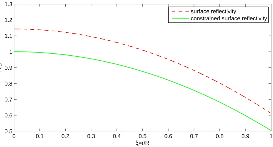
ρ(ξ) = 1− 2 (1−ν) 3−ν ξ
2 (32)
0 0.1 0.2 0.3 0.4 0.5 0.6 0.7 0.8 0.9 1 1.5
1.6 1.7 1.8 1.9 2 2.1 2.2 2.3
ξ=r/R
ρ
(
ξ
)
SRP load
[image:13.595.81.518.84.321.2]constrained SRP load
Figure 8. Non-dimensional load distribution for unconstrained parabolic deflection curve (dashed red line) and for constrained parabolic deflection (solid green line).
0 0.1 0.2 0.3 0.4 0.5 0.6 0.7 0.8 0.9 1
0.5 0.6 0.7 0.8 0.9 1 1.1 1.2 1.3
ξ=r/R
ρ
(
ξ
)
surface reflectivity
constrained surface reflectivity
Figure 9. Reflectivity distribution for unconstrained parabolic deflection curve (dashed red line) and distribution for constrained parabolic deflection (solid green line).
distribution is shown in figure 9, along with the constrained distribution that satisfies ρ≤1.
[image:13.595.81.518.371.606.2]of radius R and film thickness d, perpendicular to the Sun at a solar distance RS.
5. General performance of parabolic sail reflector
A large reflective parabolic surface deployed in space has many potential applications, such as communication, sensing and power collection. In order to evaluate the performance of the deflected shapes that can be generated, some properties of parabolic membrane reflectors will be assessed in the following.
A paraboloid concentrates incoming electro-magnetic radiation into a single focal point, depending on its geometrical precision and surface quality. The corresponding focal length, thus the focal distance from the vertex of the parabola, can be calculated after converting the expression obtained for the central deflection, equation (30), into dimensional form as
w0,C =
2p0R4 Ed
1−ν 3−ν
RS,0 RS
2!
1 3
(33)
When transforming the parabolic reference curveWP(ξ), equation (27), into dimensional form
wP =W0,Cd
r
R
2
+W0,Cd =
W0,Cd R2 r
2+W
0,Cd=ar2+c (34)
where a=w0,C/R2 and c=w0,C, the focal length can now be expressed as
f = 1 4a =
R2 4w0,C
(35)
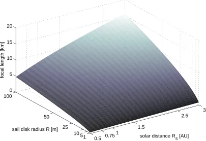
The achievable focal lengths for the deflected Kapton membranes used in section 3 are shown in figure 10, as function of radius and solar distance. For example, a deflected membrane of 100 m radius at the Earth’s distance from the Sun has a focal length fKapton = 7.54 km. However, when employing Mylar films with a currently achievable thickness of only 0.9µm [18], the focal length could be further reduced to fMylar = 6.11 km, since the focal length scales with d1/3 for the membrane thickness, according to equations (33) and (35).
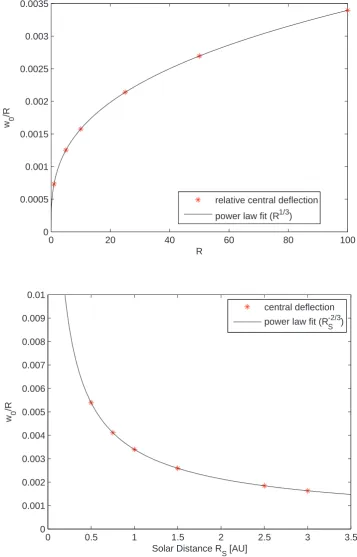
In general, the focal length of a space-based optical device shall be as small as possible in order to operate a receiver/transmitter unit in the focus. This could be achieved either by physically connecting the unit with the space reflector via a long tether, or more likely through positioning a detached platform at the focus, which is flying in formation with the reflector. Such formation-flying is a well established technology [19]. As can be seen in figure 11, the trend of the central deflectionw0,Cscales withR1/3 for the membrane radius and with 1/R2/3
0.5 0.75 1
1.5
2.5
3
1 5 10 25 50
100 0 5 10 15 20
solar distance R
S [AU]
sail disk radius R [m]
[image:15.595.89.495.89.367.2]focal length [km]
Figure 10. Achievable focal length of parabolic space reflector as function of radius and solar distance.
high costs. The second trend shows that the deflection decreases slower than 1/R2
S with solar distance (i.e. the rate at which the flux density of solar photons and thus usable electric power scale), indicating that moderate focal lengths are still available at far distances from the Sun.
6. Conclusions
0 20 40 60 80 100 0
0.0005 0.001 0.0015 0.002 0.0025 0.003 0.0035
R
w 0
/R
relative central deflection
power law fit (R1/3)
0 0.5 1 1.5 2 2.5 3 3.5
0 0.001 0.002 0.003 0.004 0.005 0.006 0.007 0.008 0.009 0.01
Solar Distance R
S [AU]
w 0
/R
central deflection
power law fit (R
S -2/3
[image:16.595.114.472.100.658.2])
Figure 11. Relative central membrane deflection as function of membrane radius R
on the membrane surface, instead of using electro-chromic coatings. Although the absolute deflection and thus focal length is changing with solar distance, this can be compensated for by a detached receiver/transmitter platform that is formation-flying at the current focus. All absolute membrane deflections for a 2.5µm polyimide Kapton film were found to be smaller than 0.6 m, even for relatively large membranes (100 m radius) and close to the Sun (half the Sun-Earth distance). The focal length of the resulting parabolic reflectors were calculated, resulting for example in 7.54 km for a 100 m radius membrane at the Earth’s distance from the Sun. Finally, when employing Mylar films with a currently achievable thickness of only 0.9µm, the focal length could be further reduced to 6.11 km, since the deflection increases for smaller membrane thickness.
Acknowledgments
This work was funded by the European Research Council Advanced Investigator Grant - 227571: VISIONSPACE: Orbital Dynamics at Extremes of Spacecraft Length-Scale.
References
[1] W.A. Imbriale, S. Gao, and L. Boccia. Space Antenna Handbook. Wiley, 2012.
[2] Proceedings of spie: Highly innovative space telescope concepts. In H. A. MacEwen, editor, Highly Innovative Space Telescope Concepts, August 22, 2002 - August 23, 2002, volume 4849 ofProceedings of SPIE - The International Society for Optical Engineering. SPIE, 2002. [3] C. Cougnet, E. Sein, A. Celeste, and L. Summerer. Solar power satellites for space exploration and
applications. In4th International Conference on Solar Power from Space, SPS ’04 - Together with The 5th International Conference on Wireless Power Transmission, WPT 5, June 30, 2004 - July 2, 2004, European Space Agency, (Special Publication) ESA SP, pages 151–158. European Space Agency, 2004.
[4] C. R. McInnes. Solar Sailing: Technology, Dynamics and Mission Applications, pages 1–55. Springer-Praxis Series in Space Science and Technology, Springer-Verlag, Berlin, 1999.
[5] Donna L. Shirley. The mariner 10 mission to venus and mercury. Acta Astronautica, 53(410):375– 385, 2003.
[6] O. Mori, Y. Tsuda, H. Sawada, R. Funase, T. Yamamoto, T. Saiki, K. Yonekura, H. Hoshino, H. Minamino, T. Endo, and J. Kawaguchi. World’s first demonstration of solar power sailing by ikaros. InProceedings of the Second International Symposium on Solar Sailing (ISSS 2010), 2010.
[7] H Demiryont and D Moorehead. Electrochromic emissivity modulator for spacecraft thermal management. Solar Energy Materials and Solar Cells, 93(12):2075–2078, 2009.
[8] J. Hill, K. W. Wang, and H. Fang. Advances of surface control methodologies for flexible space reflectors. Journal of Spacecraft and Rockets, 50(4):816–828, 2013.
[9] S. Timoshenko and S. Woinowsky-Krieger. Theory of Plates and Shells, pages 396–428. McGraw-Hill, 1959.
[10] DuPont High Performance Films. Kapton technical data sheet, Retrieved 5 November 2013. ”http://www2.dupont.com/Kapton/en US/assets/downloads/pdf/HN datasheet.pdf”.
[11] E. Ventsel and T. Krauthammer. Thin Plates and Shells: Theory, Analysis, and Applications, pages 355–358. Taylor & Francis, 2001.
[12] R.R. Craig. Mechanics of Materials. John Wiley & Sons, 2011.
[14] M Sheplak and J Dugundji. Large deflections of clamped circular plates under initial tension and transitions to membrane behavior. Journal of Applied Mechanics, Transactions ASME, 65(1):107–115, 1998.
[15] L.F. Shampine, I. Gladwell, and S. Thompson. Solving ODEs with MATLAB, pages 134–143. Cambridge University Press, 2003.
[16] F. Couceiro, P. V. Gamboa, J. M. Silva, and A. D. Guerman. Configuration of a thin circular membrane subject to solar pressure. In2012 International Conference on Spacecraft Structures, Materials and Mechanical Testing, ICSSMMT 2012, December 27, 2012 - December 28, 2012, volume 290 ofApplied Mechanics and Materials, pages 47–52. Trans Tech Publications, 2013. [17] David W. Sleight and Danniella M. Muheim. Parametric studies of square solar sails using
finite element analysis. In Collect. of Pap. - 45th AIAA/ASME/ASCE/AHS/ASC Struct., Struct. Dyn. and Mater. Conf.; 12th AIAA/ASME/AHS Adapt. Struct. Conf.; 6th AIAA NonDeterministic Approaches Forum; 5th AIAA Gossamer Spacecraft Forum, April 19, 2004 -April 22, 2004, volume 1 ofCollection of Technical Papers - AIAA/ASME/ASCE/AHS/ASC Structures, Structural Dynamics and Materials Conference, pages 85–97. American Inst. Aeronautics and Astronautics Inc., 2004.
[18] DuPont Teijin Films. Innovative polyester films brochure, Retrieved 19 November 2013. ”http://europe.dupontteijinfilms.com/Download.aspx?pdfid=147”.
![Figure 3. Reproduction of relative out-of-plane deflection for Mylar films (d = 1 µm)at Earth distance from the Sun (1 AU) for different membrane radii, found in [16].](https://thumb-us.123doks.com/thumbv2/123dok_us/1626614.115858/7.595.76.517.97.339/figure-reproduction-relative-deection-mylar-distance-dierent-membrane.webp)