A seakeeping analysis method for an air-lifted vessel
Nan Xie, D. Vassalos, A. Jasionowski, P. Sayer
Department of Naval Architecture and Marine Engineering, Universities of Glasgow and Strathclyde, Henry Dyer Building, 100 Montrose Street, Glasgow G4 0LZ, UK
a r t i c l e
i n f o
Article history:
Received 14 October 2007 Accepted 12 June 2008
Keywords: Seakeeping Frequency domain Air-lifted vessel Numerical prediction
a b s t r a c t
A seakeeping analysis in the frequency domain is presented to predict the motion response of an air-lifted vessel (ALV) in waves. The ALV is supported by pressurised air in two separate cushion chambers; the pressure variation in the cushions has a significant effect on the motions of the vessel. The adiabatic gas law is used to couple cushion pressure and the free-surface elevation of water inside the chamber. Attention is focused on the waves generated by the pressure, and a method is presented to compute the corresponding free-surface elevation. New numerical schemes are proposed for calculating the three-dimensional free-surface elevation for the four wave numbers. Numerical results of the free-surface elevation, escape area, escape volume and motion responses of the ALV are provided.
&2008 Elsevier Ltd. All rights reserved.
1. Introduction
The innovative design of an air-lifted vessel (ALV) utilises the cushioning and lubricating properties of air to generate an efficient high-speed marine vehicle. An energy saving of up to 25% is possible compared to conventional high-speed mono-hulls or catamarans, based on model experiments byAllenstrom et al. (2001, 2003).
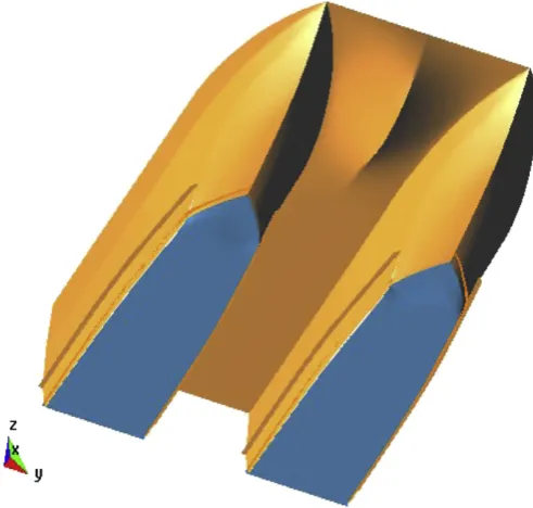
The selected ALV is a skirtless SES catamaran. There are two demi-hulls, each of which contain an air cushion (seeFig. 1). The design feature of the ALV is similar, in some sense, to that of an SES catamaran. There are two demi-hulls, each of which contains air cushions. A forward planing surface ahead of the step creates some limited dynamic lift. The step and the forward planing surface also create the forward ceiling of the air cushion chamber, the step being located in a plane close to horizontal (no part of the step is to ventilate before the other). The bow section is slender in order to reduce displacement forces in a seaway, and the bow incorporate a voluminous part above a built-in chine/spray rail to reduce water deflection and reserve buoyancy in pitching motion. The side keels of varying height extend from just ahead of the step to the transom. The height of the keels is adjusted to the observed/expected shape of the air cushion. The only purpose of the side keels is to fence in the air cushion. There are spray rails on the outside of the side keels, at a height partly to deflect the water without wetting the rails on the upper sides. The cushion ceiling is at a height to avoid being hit by waves when the vessel is moving. The ceiling aft end slopes to deflect passing waves. A flap or enclosure arrangement in line with the sloped portion of the ceiling is positioned to ‘fence’ the air cushion chamber in the rear part and to create dynamic lift and motion damping. The air
cushion concept of the present ALV is patented (EFFISES Project, 2001–2004). More details about the ALV concept can be found in Allenstrom et al. (2001).
In the ‘on-cushion’ mode, the vessel is mainly supported by the difference between the ambient atmospheric pressure and that in the plenum chamber. The pressure of the air captured in the chamber undergoes a pressure variation, and thus waves are generated on the free-surface. The dynamic response of the ALV in turn causes a reaction on the craft through the captured air, which generates further variation of the air pressure. The motions affect passenger and crew comfort as well as the performance of electronic components and machinery on board. In the present paper, a method is presented for the numerical prediction of the seakeeping performance of the ALV; this is similar to that for a surface-effect ship (SES), previously studied by other researchers, includingDoctors (1976),Chen (1977),Kim and Tsakonas (1981), Kaplan et al. (1981), andFaltinsen (2005).
As the ALV is supported by pressurised air in two separate cushion chambers, the behaviour of the craft in waves is mainly due to the pressure variation in the cushion chambers. The adiabatic gas law is used to couple cushion pressure and the free-surface elevation inside the chambers. Computations of the corresponding wave patterns are presented. Efficient and effective numerical schemes are proposed for calculating the three-dimensional free-surface elevation for the four wave numbers. Numerical results are also presented for the free-surface elevation, air cushion escape area and escape volume, and for the motion of the vessel in irregular waves.
2. Equations of motion of the ALV
A right-handed coordinate system oxyz is adopted with the plane z¼0 in the undisturbed free-surface and z positive
Contents lists available atScienceDirect
journal homepage:www.elsevier.com/locate/oceaneng
Ocean Engineering
0029-8018/$ - see front matter&2008 Elsevier Ltd. All rights reserved. doi:10.1016/j.oceaneng.2008.06.011
upwards. The origin is located at C.G. of the vessel. Frequency domain analysis method will be used in the present study. The equation of motions of the ALV can be expressed as
½M½q€ ¼ ½FH þ ½FR þ ½FP þ ½FW, (1)
whereqis the motion vector of the vessel,Mis the mass/inertia matrix,FH is the hydrodynamic force/moment,FRis the
hydro-static force/moment,FPis the force/moment due to the cushion
pressure, andFWis the wave exciting force/moment.
The adiabatic gas law and continuity equation for the air in each chamber are used to determine the cushion pressure in the port and starboard chambers:
piþpaþp0;i
r
gi¼constant;
Vid
r
i dt þr
idVi
dt ¼
r
aQin;ir
aQout;i; 8> > > < > > > :
(2)
where the subscripts i(¼1, 2) denote the port and starboard cushions, respectively; henceforth, for clarity this subscript will be omitted unless specifically required; p0 and
r
0 are cushionpressure and air density at equilibrium operating condition;pa
and
r
aare atmospheric pressure and air density;QinandQoutarethe inflow and out flow rate;Vis the cushion volume, determined by vessel motion attitude, incident wave and cushion pressure: V¼
ZZ
Ac
½Zðx;yÞ
B
pðx;yÞB
wðx;yÞdxdy (3)whereZis the cushion ceiling height,
B
wandB
pare incident waveand free-surface elevation due to cushion pressure, respectively. The outflow rate can be expressed as
Qout¼cnAL
ffiffiffiffiffiffiffiffiffiffiffiffiffiffiffiffiffiffiffiffi 2ðpþp0Þ
r
a s(4)
wherecnð0:620:8Þis the flow coefficient andALis the air escape
area of the flow opening at the cushion stern boundary: AL¼
Z yb ya
½ZðxT;yÞ
B
pðxT;yÞB
wðxT;yÞdy (5) wherexTis the longitudinal coordinate of cushion stern aperture.Nomenclature
a length of a rectangular pressure patch
ai,j i,j¼3, 4, 5, added mass for pitch, heave and roll
A parameter of wave spectra Ac cushion area
AL escape area
AL0 outflow opening area at equilibrium condition
ALW cushion opening area due to incident wave
b beam of a rectangular pressure patch bi,j i,j¼3, 4, 5, damping for pitch, heave and roll
B parameter of wave spectra
bpi i¼3, 5 coefficients for pressure and motion coupling
equation
bpp coefficient for pressure and motion coupling equation
BT width of outflow opening
cn flow coefficient
ci,j i, j¼3, 4, 5, hydrostatic restoring coefficients for
pitch, heave and roll
cpi i¼3, 5 coefficients for pressure and motion coupling
equation
cpp coefficient for pressure and motion coupling equation
E1 exponential integral
fm m¼1, 2,y, 8, function
Fn length Froude number of a pressure patch
FH hydrodynamic force/moment vector
FR hydrostatic force/moment vector
FP force/moment vector due to cushion pressure
FW wave exciting force/moment vector
Fwj j¼3, 4, 5, wave exciting force/moments
Fwp right-hand side term in the pressure and motion
coupling equation g acceleration due to gravity gm function
H1/3 significant wave height
Ijj j¼4, 5, craft mass inertia moment for roll and pitch
Jim i¼0, 1, y, 6, m¼1, 2, y, 8, terms in the wave elevation for a rectangular pressure patch
ki i¼0, 1, 2, 3, 4, wave numbers
L craft length
m index
M mass/inertia matrix
p cushion pressure pa atmospheric pressure
pi pressure in cushion chambers
p0 pressure in cushion chamber at equilibrium condition
q craft motion responses qka amplitudes of motion response
Qin inflow rate
Qout outflow rate
RMS root mean square of the motion responses Sjk j,k¼0, 1, moments of cushion area
sm m¼1, 2, y, 8, variables for wave elevation of rectangular pressure patch
SB wave spectrum T01 average wave period
u variable of functions U craft speed
V cushion volume vp escape volume
vw cushion pumping volume due to incident wave
~
vp non-dimensional escape volume x,y,z coordinates
xc,yc centre of cushion area
z heave
Z height of cushion ceiling
a
escape area~
a
non-dimensional areaa
p escape area due to cushion pressureg
ratio of specific heats for gas, Euler’s constant; also a parameter in the wave elevation integralsf
roll motion of the craftm
wave headingy
pitch motion; also a general angley
c cut-off angler
densityr
a atmospheric air densityr
0 density of air at equilibrium conditionr
w water densitys
encounter frequencyt
reduced frequencyB
p free-surface elevation due to cushion pressureB
w incident wave elevationExpanding (2) about the vessel’s equilibrium position, and assuming small amplitudes of motion for the ALV, the linearised cushion pressure equation can be written as
bppp_þcpppþbp3z_þcp3zþbp5
y
_þcp5y
þbp4f
_ þcp4f
¼Fwp (6) wherebpp¼ V0
r
1þg 0
g
p0r
0vp (7)cpp¼
r
aq
Qinq
p
0þcn
r
a AL0 ffiffiffiffiffiffiffiffiffiffiffiffiffi 2p0r
ap cn
a
ffiffiffiffiffiffiffiffi 2p0
r
a s(8)
bp3¼
r
0Ac (9)cp3¼ cn
r
aBT ffiffiffiffiffiffiffiffi 2p0r
a s(10)
bp5¼
r
0xcAc (11)cp5¼cn
r
axcBT ffiffiffiffiffiffiffiffi 2p0r
a s(12)
bp4¼
r
0ycAc (13)cp4¼ cn
r
aycBT ffiffiffiffiffiffiffiffi 2p0r
a s(14)
Fwp¼
r
0v_wþcnALw ffiffiffiffiffiffiffiffi 2p0r
a s(15) In the above,V0is the cushion volume at equilibrium condition;
(xc,yc) is the cushion centre;Acis the cushion area;
q
Qin=q
pis the discharge by fan per unit pressure; vp anda
p are the escapevolume and escape area resulting from unit cushion pressure;z,
y
,f
are heave, pitch and roll motions;AL0 is the outflow openingarea at equilibrium condition; BT is the width of the outflow
opening; vw and ALw are the cushion pumping volume and
opening area, respectively, due to the incident waves: vw¼
ZZ
Ac
B
wðx;yÞdxdy (16)ALw¼ Z yb
ya
B
wðxT;yÞdy (17)The cushion escape volume and escape area are given, respec-tively, by
vp¼ ZZ
AC
B
pðx;y;s
Þdxdy (18)a
p¼ Z ybya
B
pðxT;y;s
Þdy (19)Physically, the cushion escape volume is the volume resulting from the free-surface elevation, due to cushion pressure, inside the cushion chamber of the ALV; while the escape area is the area generated by this free-surface profile along the stern opening of the cushion chamber. The equations of heave, pitch and roll may be linearised relative to the equilibrium position of the ALV:
ðmþa33Þ€z3þb33_zþc33zþa35y€þb35y_þc35yS00ðp1þp2Þ ¼Fw3;
a53z€þb53_zþc53zþ ðI55þa55Þy€þb55y_þc55yþS10ðp1þp2Þ ¼Fw5;
ðI44þa44Þf€þb44f_þc44fS01ðp1p2Þ ¼Fw4;
8 > > < > > :
(20) whereaijandbijare the added mass and damping coefficients of
the rigid side-hull,cijis the hydrostatic restoring coefficient,Fwjis
the wave exciting force/moment, and Sjk¼
ZZ
Ac
xjykdxdy j;k
¼0;1 (21)
are the moments of the cushion area. The hydrodynamic coefficients and wave exciting force/moments on the thin rigid side-hull of each cushion are calculated by strip theory.
Hence, the transfer functions for heave, pitch and roll in regular waves can be obtained. The root mean square (RMS) values are
RMSkð
m
Þ ¼ Z 10
qkað
m
ÞB
a2
SBð
o
Þdo
!1=2
k¼3;4;5, (22) where
m
is wave heading (1801for head waves; 01for following waves). The ITTC wave spectrum was used in the present study: SBðo
Þ ¼Ao
5exp Bo
4
(23) whereA¼173:18H21=3=T
4
01and B¼692:73=T 4
01 withH1/3
signifi-cant wave height (m) andT01average wave period (s).
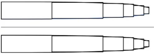
For the calculation of the transfer function of the free-surface elevation due to cushion pressure, the cushion areas are represented by a number of rectangular pressure patches, as in Fig. 2.
The major part of the computation is the calculation of the escape volume in the cushion and the escape area at the leakage openings; this is discussed in Section 3.
3. Free-surface elevation due to oscillatory cushion pressure
[image:3.595.43.289.70.304.2]In this section, a method is outlined for calculating the free-surface elevation caused by the ALV cushion pressure. The transfer function of the escape area and escape volume in the cushion will be calculated in the frequency domain. The cushion area is
modelled by rectangular pressure patches. The solution for a rectangular pressure patch provides the elementary solution of the problem. The hydrodynamic boundary value problem for a pressure patch oscillating with constant amplitude and moving on the free-surface of a deep, incompressible, ideal fluid was calculated using the corresponding velocity potential. The free-surface elevation due to a moving oscillating rectangular pressure patch with unit pressure strength can be written as, see, for example,Wehausen and Laitone (1960),Kim and Tsakonas (1981), andXie et al. (2005):
B
pðx;yÞ ¼ 1r
wgP8
m¼1ð1Þ m
ðJ0mþJ1mþJ2mþJ3mþJ4mþJ5mþJ6mÞ 4
r
wgp
2(24) Here,
r
wis the density of water, andJ0m¼ Z p=2
0
2
sin
y
cosy
lnjsmðy
Þjdy
(25)J1m¼ Z p=2
0
½E1ðik1smÞ
p
ið1sgnðsmÞÞeik1smsin
y
cosy
pffiffiffiffiffiffiffiffiffiffiffiffiffiffiffiffiffiffiffiffiffiffiffiffiffiffiffi1þ4t
cosy
dy
(26)J2m¼ Z p=2
0
½E1ðik2smÞ
p
ið1sgnðsmÞÞeik2smsin
y
cosy
pffiffiffiffiffiffiffiffiffiffiffiffiffiffiffiffiffiffiffiffiffiffiffiffiffiffiffi1þ4t
cosy
dy
(27)J3m¼ Z p=2
yc
E1ðik3smÞeik3sm sin
y
cosy
pffiffiffiffiffiffiffiffiffiffiffiffiffiffiffiffiffiffiffiffiffiffiffiffiffiffiffi14t
cosy
dy
p
Zp=2
yc
sinðk3smÞ½1þsgnðsmÞ sin
y
cosy
pffiffiffiffiffiffiffiffiffiffiffiffiffiffiffiffiffiffiffiffiffiffiffiffiffiffiffi14t
cosy
dy
i
p
Z p=2
yc
cosðk3smÞ½1þsgnðsmÞ
sin
y
cosy
pffiffiffiffiffiffiffiffiffiffiffiffiffiffiffiffiffiffiffiffiffiffiffiffiffiffiffi14t
cosy
dy
(28)J4m¼ Z p=2
yc
E1ðik4smÞeik4sm sin
y
cosy
pffiffiffiffiffiffiffiffiffiffiffiffiffiffiffiffiffiffiffiffiffiffiffiffiffiffiffi14t
cosy
dy
p
Zp=2
yc
sinðk4smÞ½1sgnðsmÞ sin
y
cosy
pffiffiffiffiffiffiffiffiffiffiffiffiffiffiffiffiffiffiffiffiffiffiffiffiffiffiffi14t
cosy
dy
i
p
Z p=2
yc
cosðk4smÞ½1sgnðsmÞ
sin
y
cosy
pffiffiffiffiffiffiffiffiffiffiffiffiffiffiffiffiffiffiffiffiffiffiffiffiffiffiffi14t
cosy
dy
(29)J5m¼ i Z yc
0
E1ðik3smÞeik3sm sin
y
cosy
pffiffiffiffiffiffiffiffiffiffiffiffiffiffiffiffiffiffiffiffiffiffiffiffiffiffiffi4t
cosy
1dy
p
2 Zyc
0
ek3ism cosðk
3rsmÞ½1þsgnðsmÞ
sin
y
cosy
pffiffiffiffiffiffiffiffiffiffiffiffiffiffiffiffiffiffiffiffiffiffiffiffiffiffiffi4t
cosy
1 ½1þsgnðk3rÞdy
þip
2 Z yc
0
ek3ism sinðk
3rsmÞ½1þsgnðsmÞ
sin
y
cosy
pffiffiffiffiffiffiffiffiffiffiffiffiffiffiffiffiffiffiffiffiffiffiffiffiffiffiffi4t
cosy
1 ½1þsgnðk3rÞdy
(30)J6m¼i Z yc
0
E1ðik4smÞeik4sm sin
y
cosy
pffiffiffiffiffiffiffiffiffiffiffiffiffiffiffiffiffiffiffiffiffiffiffiffiffiffiffi4t
cosy
1dy
p
2 Z yc
0
ek4ism cosðk
4rsmÞ½1sgnðsmÞ
sin
y
cosy
pffiffiffiffiffiffiffiffiffiffiffiffiffiffiffiffiffiffiffiffiffiffiffiffiffiffiffi4t
cosy
1 ½1þsgnðk4rÞdy
þip
2 Z yc
0
ek4ism sinðk
4rsmÞ½1sgnðsmÞ
sin
y
cosy
pffiffiffiffiffiffiffiffiffiffiffiffiffiffiffiffiffiffiffiffiffiffiffiffiffiffiffi4t
cosy
1 ½1þsgnðk4rÞdy
(31) Furthermore, E1½iklsm is the exponential integral of complex argument (Abramowitz and Stegun, 1970):E1ðzÞ ¼ Z1
z eu
u du¼
g
logz X1n¼1 ð1Þnzn
nn! (32)
where
g
¼0.5772yis Euler’s constant. Finally,y
c¼tg1 1
4t ;
t
40:25 0;t
o0:25 ((33)
smð
y
Þ ¼ðxaÞcos
y
þ ðybÞsiny
; m¼1 ðxaÞcosy
þ ðyþbÞsiny
; m¼2 ðxþaÞcosy
þ ðyþbÞsiny
; m¼3 ðxþaÞcosy
þ ðybÞsiny
; m¼4 ðxaÞcosy
ðyþbÞsiny
; m¼5 ðxaÞcosy
ðybÞsiny
; m¼6 ðxþaÞcosy
ðybÞsiny
; m¼7 ðxþaÞcosy
ðyþbÞsiny
; m¼8 8 > > > > > > > > > > > > > > < > > > > > > > > > > > > > > : (34)whereaandbare half-length and beam of the rectangular. The four wave numbers are
k1¼12k0sec2
y
½1þ2t
cosy
ffiffiffiffiffiffiffiffiffiffiffiffiffiffiffiffiffiffiffiffiffiffiffiffiffiffiffi 1þ4
t
cosy
p
, (35)
k2¼12k0sec2
y
½1þ2t
cosy
þffiffiffiffiffiffiffiffiffiffiffiffiffiffiffiffiffiffiffiffiffiffiffiffiffiffiffi 1þ4
t
cosy
p
, (36)
k3¼12k0sec2
y
½12t
cosy
ffiffiffiffiffiffiffiffiffiffiffiffiffiffiffiffiffiffiffiffiffiffiffiffiffiffiffi 14
t
cosy
p
, (37)
k4¼12k0sec2
y
½12t
cosy
þffiffiffiffiffiffiffiffiffiffiffiffiffiffiffiffiffiffiffiffiffiffiffiffiffiffiffi 14
t
cosy
p
, (38)
where k0¼ ðg=U2Þ is wave number,
t
¼ ðUs
=gÞ is the reduced frequency, ands
is the encounter frequency.We also note that: lim
y!p=2fk1g ¼k0
t
2¼s
2g ; y!plim=2fk2g ¼ þ1, (39)
lim
y!p=2fk3g ¼k0
t
2¼s
2g ; y!plim=2fk4g ¼ þ1. (40)
The evaluation of the free-surface elevation (24) is hampered by singularities in the integrand ofJim, and by their highly oscillatory
behaviour. For example, the integrand of J0m becomes infinite
when
y
-0 andy
-p
/2; alsok2sm! 1asy
-p
/2.To overcome these difficulties, we write Fmð
y
Þ ¼fmðy
Þ=gmðy
Þ, wherefm(y
) is regular andgm(y
) has a zero of order one aty
¼y
a.Thus, the integral ofFm(
y
) may be written asIm¼ Zyb
ya fmð
y
Þ gmðy
Þdy
¼Z yb
ya fmð
y
Þ gmðy
Þfmð
y
aÞ g0mð
y
aÞðy
y
aÞd
y
þ Zyb
ya
fmð
y
aÞ g0mð
y
aÞðy
y
aÞdy
. (41)On the right-hand side of (41), we observe that the integrand of the first integral is regular at
y
¼y
a; furthermore, the secondintegral makes no contribution to the summation in (24). The same approach can be applied to the case when
y
¼y
b. In this [image:4.595.33.282.68.156.2]way, the singularities in the integrals of the free-surface elevation may be removed.
In the case ofJ3m,J4m,J5mandJ6m, there is a singularity of order
1/2 at
y
¼y
cwhich is integrable:ffiffiffiffiffiffiffiffiffiffiffiffiffiffiffiffiffiffiffiffiffiffiffiffiffiffiffi 14
t
cosy
p
¼ ffiffiffi 2
t
r ffiffiffiffiffiffiffiffiffiffiffiffiffiffiffiffiffiffiffiffiffiffiffiffiffiffiffi sin
y
þy
c2
s ffiffiffiffiffiffiffiffiffiffiffiffiffiffiffiffiffiffiffiffiffiffiffiffiffiffiffi sin
y
y
c2
s
(42)
when
y
2 ðy
c;p
=2Þ, and a direct integration scheme can be used to calculateJ0m,J1m,J3mandJ5mandJ6min (24).It then remains to calculate J2m and J4m. Their integrands
become highly oscillatory when
y
-p
/2. Following Xie et al. (2005):u¼ j
g
j siny
cos2
y
(43)and where
g
¼ ðybÞ=2aF2n (m¼1, 4, 6, 7), org
¼ ðxaÞ=2aF 2 n (m¼2, 3, 5, 8), whereFn¼U=pffiffiffiffiffiffiffiffi2agis the Froude number for the element. Thus, the oscillatory behaviour is ‘stretched’:k2s1¼
c
ðy
Þffiffiffiffiffiffiffiffiffi 2
a
u pffiffiffiffiffiffiffiffiffiffiffiffiffiffiffiffiffiffiffiffiffiffiffiffiffiffiffiffiffiffiffiffiffiffiffiffiffiffiffiffi j
g
jpffiffiffiffiffiffiffiffiffiffiffiffiffiffiffiffiffiffiffiffiffiffiffiffiffiffiffiffiffiffi4u2þg
2g
2q þ
g
j
g
ju 26 4
3 7
5 (44)
where
a
¼ ðxaÞ=2aF2n,c
ðy
Þ ¼0:5ð1þ2t
cosy
þffiffiffiffiffiffiffiffiffiffiffiffiffiffiffiffiffiffiffiffiffiffiffiffiffiffiffi 1þ4
t
cosy
p
. Care is also advised when handling the logarithmic singula-rities in the free-surface elevation integrals (25)–(31).
4. Numerical results
A rectangular pressure patch is selected for validation of the numerical schemes outlined in Section 3. The length-beam ratio of the pressure patch is a/b¼1 and patch length Froude numberFn¼0.50. The free-surface elevations of the rectangular
pressure patch at reduced frequencies of
t
¼0.2375 and 0.275 (below and above the critical value of 0.25) are compared with existing results. Due to the phase effect, there are real (Re) and imaginary (Im) parts for the free-surface elevation. The same applies to the escape area and escape volume. Wave-cuts at y¼bwere compared with those ofDoctors (1976), who used a different numerical scheme. The agreement was good (seeFigs. 3 and 4).The non-dimensional free-surface elevation per unit pressure is defined as:
~
B
p¼r
wgB
p. (45)The corresponding non-dimensional escape area and escape volume per unit pressure are
~
a
¼r
wga
L (46)
~ vp¼
r
wgvpL2 (47)
Numerical predictions were also carried out for an ALV having principal dimensions as given inTable 1.
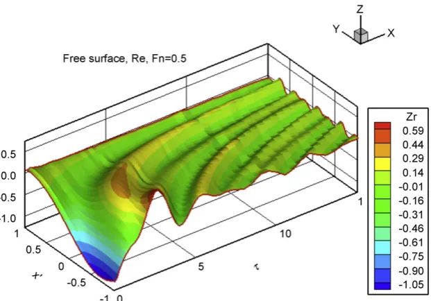
The cushion area of the ALV is divided into a number of rectangular elements (see Fig. 2). Some convergence studies have been carried out to find the proper discretisation scheme. Figs. 5 and 6show real and imaginary part of the non-dimensional free-surface elevation at the cushion longitudinal outer boundary whenFn¼0.5, respectively. The free-surface elevation is smooth
both in space and reduced frequency due to proper handling of the singularities and the high oscillating behaviour. It can be also observed that the free-surface decrease as the reduced
frequency,
t
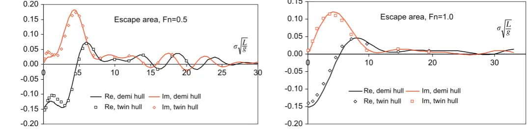
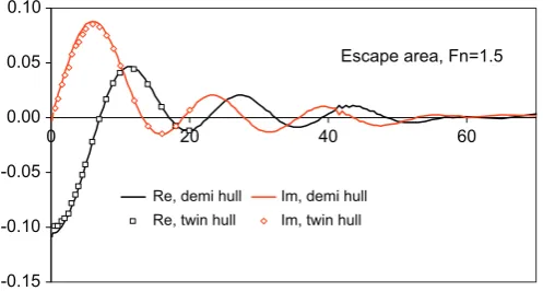
, increases, which mean that at high (reduced) frequencies, the free-surface elevation responses much less. Figs. 7 and 8 show non-dimensional free-surface elevations at the stern of the ALV when Fn¼1.0. The calculatednon-dimensional escape areas at the stern opening of the ALV for Froude numbers Fn¼0.5, 1.0, 1.5 are shown in Figs. 9–11,
respectively. Both demi-hull and twin-hull results are given. In the twin-hull calculation cases, the effect of pressure of one demi-hull on the free-surface elevation of another demi-hull is taken into consideration. It can be seen that the demi-hull has some effect on the escape area of the other demi-hull only for Fn¼0.5 and at lower values of frequency. With vessel
speed increase, this effect become much less and may be neglected. The escape areas decay quickly with increasing encounter frequency. Also the magnitude of the escape area at lower Froude number is larger than that at higher Froude numbers. Since the craft is normally operating at high speed, this may be probably the reason the craft has good seakeeping
1.5
1.0
0.5
0.0
0.5
-3 -2 -1
-1.0
-1.5
0 1 2 3 4
Fn=0.50 Re, present Re, Doctors' lm, present lm, Doctors'
4
[image:5.595.314.562.69.220.2]x/a
Fig. 3. Non-dimensional free-surface elevationB~py¼bfor a rectangular pressure
patch,b/a¼1,t¼0.2375.
1.5
1.0
0.5
0.0
-0.5
-1.0
-1.5
-4 -3 -2 -1 0 1 2 3
Fn=0.50 x/a
4 Re, present Re, Doctors' lm, present lm, Doctors'
Fig. 4. Non-dimensional free-surface elevationB~py¼bfor a rectangular pressure
[image:5.595.315.562.269.424.2]patch,b/a¼1,t¼0.275.
Table 1
Principal dimensions of the ALV
Length,LOA(m) 40.0
Displacement,D(m3) 170
Breadth,B(m) 15.0
[image:5.595.310.562.499.541.2]performance. The cushion escape volumes of the ALV for Froude numbersFn¼0.5, 1.0, 2.0 are shown inFigs. 12–14, respectively.
The trends are similar to that of the escape area, there will be less free-surface disturbance inside the cushion of the ALV for higher vessel speed.
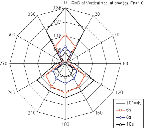
Using the computed values (46) and (47) in (6) and (20) yields the transfer functions for heave, pitch and roll, from which the spectral responses may be obtained. The RMS of heave, pitch and vertical acceleration on bow of the ALV atFn¼1.0 and four mean
wave periods T01¼4, 6, 8 and 10 s are plotted in Fig. 15–17,
respectively, for all heading angles at interval of 301. Generally speaking, there will be less craft responses for shorter waves
(smaller mean wave periods). Also, the vehicle has less response to head wave than to following seas, this may be due to the characteristics of the free-surface elevation, escape area and escape volume of the cushion of the ALV. At high values of the reduced frequency, the escape area and escape volume both tend to zero: the vessel rides the waves. Figs. 18 and 19 show heave and vertical acceleration at bow of the ALV at Fn¼1.5,
[image:6.595.139.450.67.284.2]respectively. Again, the vertical acceleration on bow at following waves is much larger than that at head waves. Although there is no experimental results available for validation of the approach at this stage, the results obtained by the present approach seems reasonable.
Fig. 5.Real part ofB~pat cushion outer boundary of the ALV.
[image:6.595.138.450.339.585.2]Fig. 7.Real part ofB~pat cushion stern boundary of the ALV.
Fig. 8.Imaginary part ofB~pat cushion stern boundary of the ALV.
0.20
0.15
0.10
0.05
0.00
-0.05
-0.10
-0.15
-0.20
Escape area, Fn=0.5
Re, demi hull Re, twin hull
Im, demi hull Im, twin hull
5
0 10 15 20 25 30
Lg
Fig. 9.Non-dimensional escape areaa~pat stern of the ALV.
0.15
0.10
0.05
0.00
-0.05
-0.10
-0.15
-0.20
0 10 20 30
Re, demi hull Re, twin hull
Im, demi hull Im, twin hull
Escape area, Fn=1.0
[image:7.595.24.563.610.743.2]L g
5. Conclusions
A mathematical model has been developed to predict the seakeeping performance of an ALV in the frequency domain. The external forces/moments acting on the hull arise from hydrodynamic (added mass and damping) loads, wave excita-tion—calculated by strip theory—and cushion pressure effects. Attention has focused on the latter: the present method is based on a moving, oscillatory pressure patch. A efficient and effective numerical scheme has been proposed to handle the singularities and highly oscillatory behaviour of several integrands. Results are in good agreement with available published data for the free-surface elevation in the cushion. Numerical results for the escape area, escape volume, and for the vessel motions of the ALV are 0.10
0.05
0.00
-0.05
-0.10
-0.15
0 20 40 60
Re, demi hull Re, twin hull
Im, demi hull Im, twin hull
[image:8.595.35.284.71.204.2]Escape area, Fn=1.5
Fig. 11. Non-dimensional escape areaa~pat stern of the ALV.
0.10
0.05
0.00
-0.05
-0.10
-0.15
5 10
Re lm
L g
15 20
Escape Volume, Fn=0.5
0
[image:8.595.306.553.72.285.2]0.15
Fig. 12.Non-dimensional escape volumev~pof the ALV.
0.10
0.05
0.00
-0.05
-0.10
-0.15
0 20 40
Re lm
L g
60 Escape Volume, Fn=1.0
[image:8.595.34.282.239.380.2]
Fig. 13.Non-dimensional escape volumev~pof the ALV.
0.06
0.04
0.02
0.00 0 -0.02
-0.04
-0.06
-0.08
20
Real lm
40
gL 60 Escape Volume, Fn=2.0
[image:8.595.306.553.342.566.2]Fig. 14.Non-dimensional escape volumev~pof the ALV.
Fig. 15.RMS of heave motion of the ALV atFn¼1.0 forH1/3¼1 m.
[image:8.595.35.282.415.554.2] [image:8.595.37.281.590.742.2]provided and discussed. The present method therefore appears to provide a helpful means of assessing performance at both design and operational stages.
References
Abramowitz, M., Stegun, I.A., 1970. Handbook of Mathematical Functions. Dover Publications Inc., New York.
Allenstrom, B, Liljenberg, H., Tuden, U., 2001. An Air lifted catamaran. In: Proceedings of the FAST 2001, Southampton, UK.
Allenstrom, B., Liljenberg, H., Tuden, U., 2003. Concept development and model testing—new generation air assisted vessels (AVV) with water jet propulsion. In: Proceedings of the FAST 2003, Naples, Italy.
Chen, H.H., 1977. On a rectangular pressure distribution of oscillating strength moving over a free surface. Journal of Ship Research 21 (1), 11–23.
Doctors, L.J., 1976. The effect of air compressibility on the nonlinear motion of an air-cushion vehicle over waves. In: Proceedings of the 11th ONR Symposium on Naval Hydrodynamics, UCL, London, pp. 373–388.
EFFISES Project, 2001–2004. Energy Efficient Safe Innovative Ships and Vehicle, European Commission CEC Contract no. GRD1-2000-25847, coordinated by SES Europe.
Faltinsen, O.M., 2005. Hydrodynamics of High-Speed Marine Vehicles. Cambridge University Press.
Kaplan, P., Bentson, J., Davis, S., 1981. Dynamics and hydrodynamics of surface effect ships. Transactions of the SNAME 89, 211–247.
Kim, C.H., Tsakonas, S., 1981. An analysis of heave added mass and damping of a surface effect ship. Journal of Ship Research 25 (1).
Wehausen, J.V., Laitone, E.V., 1960. Surface waves in fluid dynamics III. In: Flugge, S., Truesdell, C. (Eds.), Handbuch der Physik, vol. 9. Springer, Berlin, pp. 446–778 (chapter 3).
[image:9.595.45.294.69.288.2]Xie, N., Vassalos, D., Jasionowski, A., 2005. A study of the hydrodynamics of a three-dimensional planing surface. Ocean Engineering 32, 1539–1555.
[image:9.595.314.561.72.286.2]Fig. 18.RMS of heave motion of the ALV atFn¼1.5 forH1/3¼1 m.
Fig. 19.RMS of vertical acceleration at bow of the ALV atFn¼1.5 forH1/3¼1 m.
[image:9.595.47.292.330.527.2]