Int. J. Electrochem. Sci., 13 (2018) 5413 – 5424, doi: 10.20964/2018.06.21
International Journal of
ELECTROCHEMICAL
SCIENCE
www.electrochemsci.org
Study on Highly Compacted LiFePO
4/ C Cathode Materials for
High-performance 18650 Li-ion Batteries
Lei Chen1,*, Zhenyu Chen1, Shuaishuai Liu2, Haitao Zhang3,* and Quanzhen Huang4
1
School of Materials and Chemical Engineering, Henan University of Engineering, Zhengzhou 450006, People's Republic of China
2
Center of Analysis and Testing, Henan University of Engineering, Zhengzhou 451191, People's Republic of China
3
Institute of Process Engineering, Chinese Academy of Sciences, Beijing 100190, People's Republic of China
4
School of Electrical Information and Engineering, Henan University of Engineering, Zhengzhou 451191, People's Republic of China
*
E-mail: [email protected], [email protected]
Received: 8 February 2018 / Accepted: 25 March 2018 / Published: 10 May 2018
The porous spherical LiFePO4 (LFP) nanostructures were synthesized by a spray drying technology,
followed by a calcination process. Effect of compacted density on the electrochemical performance of the 18650 cells, which employed as-prepared spherical LFP materials, was investigated systemically. The morphology study and physical characterization results show that the spherical LFP/C are composed of numerous particles with an average size of 300 nm, and have well-developed interconnected pore structure and a specific surface area of 12-15 m2/g. For CR2032 coin-type cell, the specific discharge capacity of the LFP/C was 162-164 mAh/g at 0.2C, and the capacity retention can reach up to 100% after 50 cycles at 1 C. For 18650 batteries, the cathode slurry viscosity of the LFP/C with LiOH as lithium source is larger than that with Li2CO3 as lithium source. For the sintering
temperature of the LFP material is reduced to 700 oC, meanwhile the carbon content is reduced to 1.1%, the compacted density of the LFP material electrode can reach 2.47 g/cm3.
Keywords: Porous spherical LiFePO4; 18650 Cells; Highly compacted density; Cathode slurry
viscosity
1. INTRODUCTION
Olivine-structure lithium iron phosphate LiFePO4 (LFP) has attracted extensive attentions due
commercial application in high-rate lithium-ion batteries. Therefore, many efforts have been proposed by many investigators to improve this conductivity, e.g. refining the grain to nanoscale to shorten the bulk diffusion distance of Li+ ions, metal doping, carbon coating, and co-synthesis with carbon in powder metallurgy method.[4-7] The spherical preparation of the LFP material synthesized by sol-gel method, solid-state reaction, hydrothermal, and solvothermal has greatly improved the electrochemical performance of the material. The micro-spherical particles can easily move, closely pack and occupy the available vacancies. Porous micro-spherical aggregates of LFP/C nanocomposites can effectively improve diffusion channels of Li+ by reducing particle size. Meantime, the growth of the LFP particle is suppressed by the carbon.[8-10]
The film thickness and compacted density of the electrode affect the electrochemical performance and are therefore crucial for battery design.[11-14] The electrochemical performance of the LFP electrodes depend strongly on film thickness, with the largest rate capability for the thinnest film.[15] The effect of the different compacted densities on the electrochemical characteristics of lithium cobalt oxide electrode has been studied.[16] The higher the compaction density of the electrode, the smaller the average void, the narrower the size distribution of the void, and the higher the contact strength between the electrode material and the binder. By decreasing the particle size of the electrode material, the electrochemical performance and the capacity performance of the material can be improved.
At present, the high-capacity spherical LFP material has been widely reported, but the research of the compacted density and rate performance is lack for the commercial 18650 battery.
2. EXPERIMENTAL
LiFePO4/C compounds were prepared via solid-state reaction. A mixture of the as-synthesized
FePO4, glucose, and different Li sources (Li2CO3, LiOH) were mixed into ethanol and ball-milled for
20 h to obtain precursor slurry. Then the mixture was spray-dried at 200 oC and 80 oC (inlet and outlet temperatures, respectively) at a feed of 300 mL/h to obtain the precursor (light yellow precipitate). The precursor was heated at 550 oC for 5 h under nitrogen flux and subsequently sintered at 700 oC or 715
o
C for 12 h still under nitrogen flux, to obtain the final micro-spherical LiFePO4/C. The final obtained
samples were denoted as LFP-Li2CO3-1.3%C-715, LFP-LiOH-1.3%C-715, LFP-Li2CO3-1.1%C-715,
and LFP-Li2CO3-1.1%C-700 with respect to the different Li source, different carbon content, and
different sintered temperature.
The powder X-ray diffraction (D8 ADVANCE, Bruker) measurement using Cu Kα radiation
The electrochemical characterizations were performed using CR2032 coin-type cell. Typical positive electrode loadings were in the range of 2-2.5 mg/cm2, and an electrode diameter of 14 mm was used. For positive electrode fabrication, the prepared LiFePO4/C compounds were mixed with
10% of carbon black and 10% of polyvinylidene fluoride in N-methyl pyrrolidinone until slurry was obtained. Then, the blended slurries were pasted onto an aluminum current collector, and the electrode was dried at 120 oC for 12 h in the argon armosphere. The test cell consisted of the positive electrode and lithium foil negative electrode separated by a porous polypropylene film, and 1 mol/L LiPF6 in
ethylene carbonate, diethyl carbonate, and dimethyl carbonate (1:1:1 in volume) as the electrolyte. The assembly of the cells was carried out in a dry Ar-filled glove box. The discharge-charge cycling is galvanostatically performed from 0.2C to 1C rate with cut-off voltages of 2.0-4.2 V (versus Li/Li+) at 25 oC by using an automatic galvanostatic charge-discharge unit, Neware battery cycler, and the electrochemical capacity of samples was evaluated based on the active materials.
18650 lithium-ion batteries (18 mm in diameter and 65 mm in height) were assembled. The capacity of the batteries was nominally designed to be 1500 mAh corresponding to the specific capacity of the half cell. The batteries used LFP materials as cathode, graphite as anode, and polyethylene as separator. The positive electrodes consisted of 91.5 wt % LFP, 4 wt% conductive materials, and 4.5 wt% PVDF. The loading amount of the cathode material on each side of the electrode was about 15 mg cm−2. The negative electrode consisted of 94.5 wt% FT-1 graphite, 1.5 wt% CMC, 1.5 wt% SP, and 2.5 wt% styrene-butadiene rubber (SBR, Jinbang Power Source Co., LTD), 2 wt% CMC. The loading amount of the anode material on each side of the electrode was about 7 mg cm−2. A certain amount of electrolyte was injected in an argon filled glove box. The formation, rate capability and cycle performance tests of batteries were performed by using Neware battery test systems. For the formation process, the experimental batteries in this study underwent one cycle of charge-discharge. The batteries were charged with a constant current of750 mA (0.5 C) and 1500 mA (1 C), respectively, followed by holding the voltage at 4.5V until the current dropped to 75 mA (0.05 C), while the batteries were discharged at 750 mA (0.5 C) and 1500 mA (1 C) to a cut-off voltage of 2.5V. The two batteries were charged with a constant current of 750 mA (0.5 C), while the rate capabilities of batteries were examined at the discharge rate of 750 mA (0.5 C), 1500 mA (1 C), 3000 mA (2 C), 4500 mA (3 C), 6000 mA (4 C), 7500 mA (5 C), 9000 mA (6 C), 10500 mA (7 C), 12000 mA (8 C)respectively under the voltage of 2.5-4.4V. The surface temperature of batteries was recorded during the rate-discharge performance testing. A type-K thermal couple was attached to the center of the largest face of the batteries to record the temperature change.
3. RESULTS AND DISCUSSION
[image:4.596.175.416.225.411.2]
nanoparticles and interconnected pores. The interconnected pores can enhance the infiltration of liquid electrolyte to the electrode materials and increase the transport rate of Li+ in the microspheres. As seen in Figure 3, the size of the larger microspheres is about 1000 nm, and the smaller particle is about 100 nm. And a carbon layer was coated on the surface of the microspheres. The microspheres are composed of primary nanoparticles with a size of approximately 300 nm, and the interconnected pores distribute uniformly around the primary nanoparticles. Theoretically, a small particle size means small diffusion length and large surface reaction sites for lithium ion, which can improve the lithium-ion intercalation kinetics and even the electrochemical performance of materials.[5, 17]
Figure 1. XRD patterns of LiFePO4 materials
Figure 2. SEM images of LiFePO4 materials: (a) LFP-Li2CO3-1.3%C-715, (b) LFP-LiOH-1.3C-715,
[image:4.596.129.472.462.725.2]
Figure 3. TEM image of LFP-Li2CO3-1.1%C-700
As shown in Table 1, the tap density of the prepared LFP is approximately 1.1-1.2 g/cm3. This result is similar to the tap density of lithium iron phosphate prepared by the carbothermal reduction method in other literatures.[19] However, the tap density of LFP prepared by sol-gel method or molten salt methods can usually reach 1.4-1.5 g/cm3.[6, 19] Therefore, for the carbothermal reduction method, the tap density needs to be further improved. In practical applications, the tap density of an active material is important because it influences the volumetric capacity of the battery. The high tap density enhances the volumetric energy density and provides advancement in energy supply applications. The Brunauer-Emmett-Teller surface area of the material were calculated by the N2 adsorption-desorption
method.
Table 1. The physical properties of LiFePO4 materials
Samples Tap density
a
,
g/cm3 Specific surface area
a
, m2/g Carbon contenta, wt %
LFP-Li2CO3-1.3%C-715 1.12 15.25 1.33
LFP-LiOH-1.3C-715 1.20 16.14 1.35
LFP-Li2CO3-1.1%C-715 1.21 12.96 1.14
LFP-Li2CO3-1.1%C-700 1.18 12.60 1.12
a
The experimental errors for tap density, specific surface area, carbon content were within 3, 10, and 8%, respectively.
[image:5.596.163.434.74.260.2]
composite, the carbon content of 1.1-1.3 wt% not only ensured the high conductivity but also contributed to the high tap density of the material. The XPS analysis is employed to further understand the surface elemental compositions and the chemical states of elements. As illustrated in Figure 4, the XPS full survey of the LFP-Li2CO3-1.1%C-700 shows some peaks at 56.4, 133.8, 190.9, 284.9, 531.6,
and 711.9 eV, corresponding to Li 1s, P 2p, P 2s, C 1s, O 1s and Fe 2p, respectively. Deconvolution of the Fe 2p XPS spectrum illustrates the presence of Fe 2p doublet (Fe 2p3/2 and Fe 2p1/2), which is
characteristic for Fe2+ (Figure 4b).[21, 22]
[image:6.596.125.476.207.469.2]Figure 4. (a) X-ray photoelectron spectroscopy full survey spectra and peaks (b) Fe 2p (c) C 1s (d) P 2s 2p for LFP-Li2CO3-1.1%C-700
Figure 5. Charge-discharge voltage profiles of LFP-Li2CO3-1.1%C-700 for CR2032 coin-type cell at
[image:6.596.172.430.535.726.2][image:7.596.35.557.148.329.2]
The initial charge-discharge capacities of the LFP samples at 0.2 C, 0.5 C, 1 C rate are illustrated in Figure 5 and Table 2.
Table 2. The charge and discharge data of LiFePO4 materials for CR2032 coin-type cell
Samples Item
LFP-Li2CO3
-1.3%C-715
LFP-LiOH -1.3C-715
LFP-Li2CO3
-1.1%C-715
LFP-Li2CO3
-1.1%C-700 0.2C charge capacity(mAh/g) 165.79 167.20 167.41 168.45 0.2C discharge capacity(mAh/g) 162.00 164.25 162.19 163.85
0.2C discharge efficiency(%) 97.71 98.24 96.88 97.27
0.5C Charging capacity(mAh/g) 162.45 164.58 161.75 164.19 0.5C discharge capacity(mAh/g) 159.14 161.93 159.38 161.89
0.5C discharge efficiency(%) 97.96 98.39 98.64 98.60
1C Charging capacity(mAh/g) 160.03 162.93 159.88 162.34 1C discharge capacity(mAh/g) 155.12 159.15 156.38 158.89
1C discharge efficiency(%) 96.94 97.68 97.81 97.88
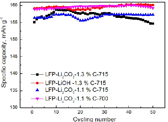
The specific discharge at 0.2 C rate can reach up to 162-164 mAh/g, corresponding to 95.3-96.5 % of the theoretical capacity (170 mAh/g), better than most of similar investigations.[19-21] As the current rates change to 0.5 C and 1 C, the initial discharge capacities are 159-161 and 155-159 mAh/g, respectively. For the LFP material sintered at different temperatures and contented different carbon, the difference of the discharge capacity is little. Preparation of LFP material by ball milling and solid phase reaction, the effect of different lithium source and temperature on the button half-cell test is not significant. The discharge capacity at high current rates is heavily dependent on the rapid transference of electrons between particles. The discharge efficiency of the LFP samples at 0.2 C and even at 1 C rate is 96 %, which indicate that lithium ions can be free to shuttle back and forth in the charge and discharge process between the LFP samples and lithium metal. The specific capacity retentions are nearly 100 % after 50 cycles at 1 C, as shown in Figure 6.
[image:7.596.168.440.549.747.2]
This result indicates that the prepared LFP samples shares good conductive ability and cycling stability. The fluctuations within a narrow range are contributed to the electrolyte decomposition with increasing temperature during the prolonged cycle process. The high specific capacities and good cycling stability are attributed to the special porous nano/micro structure of the microspheres and the small Li+ diffusion resistance.
The LFP samples were prepared into slurry, in which the mixing materials are active material: Super-P+KS-6: PVDF = 91.5: 4: 4.5. As shown in Table 3, the solids content of the slurry is between 42 and 48 %, and the viscosity of the slurry is between 4600 and 6300 Pa·s. The maximum viscosity is present in the slurry of LFP-LiOH-1.3%C-715 material prepared from LiOH as Li sources. The minimum value of the viscosity appears in the slurry with the smallest solid content of LFP-Li2CO3
-1.1%C-715 material with Li2CO3 as the raw material. The cathode slurry viscosity of the LFP/C with
LiOH as lithium source is larger than that with Li2CO3 as lithium source. This may be the difference of
the alkaline surface of the LFP material prepared form different lithium sources, resulting in different interaction forces between the material and the solvent and the binder. Thus the Li2CO3 as lithium
source is suitable for the lower viscosity slurry.
[image:8.596.50.548.429.520.2]The LFP slurries were coated on the 16 micrometer aluminum foil for both sides, and the density of both sides was 30 ± 0.3 mg/cm2. After the roll press, the compacted density of the LFP material electrode is very different.
Table 3. Homogenization parameters of LiFePO4 materials for 18650 batteries
Samples Solid content Viscosity, Pa·s
LFP-Li2CO3-1.3%C-715 48.0 % 5500
LFP-LiOH-1.3%C-715 45.0 % 6320
LFP-Li2CO3-1.1%C-715 42.4 % 4650
LFP-Li2CO3-1.1%C-700 45.8 % 5900
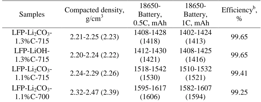
Table 4. The compacted density and discharge capacity of LiFePO4 materials for 18650 batteriesa
Samples Compacted density, g/cm3 18650-Battery, 0.5C, mAh 18650-Battery, 1C, mAh
Efficiencyb, % LFP-Li2CO3
-1.3%C-715 2.21-2.25 (2.23)
1408-1428 (1418)
1402-1424
(1413) 99.65
LFP-LiOH-1.3%C-715 2.20-2.24 (2.22)
1412-1430 (1421)
1408-1425
(1416) 99.65 LFP-Li2CO3
-1.1%C-715 2.24-2.29 (2.26)
1518-1542 (1530)
1510-1532
(1521) 99.41 LFP-Li2CO3
-1.1%C-700 2.32-2.47 (2.39)
1595-1617 (1606)
1582-1607
(1594) 99.25
a
The data in parentheses are averaged.
b
[image:8.596.89.505.573.736.2]
As shown in Table 4, for the LFP material sintered at 715 oC and carbon content of 1.3 %, the compacted density of the electrode cannot be greater than 2.25 g/cm3, otherwise the electrode brittle. For the sintering temperature of the material is reduced to 700 oC, meanwhile the carbon content is reduced to 1.1%, the compacted density of the LFP material electrode can reach 2.47 g/cm3. It is possible that due to the hardness of the LFP material sintered at lower temperatures is lower, and the lower carbon content can reduce the binder adsorption and improve the binder bonding performance. For the LFP material sintered at different temperatures and different carbon content, the discharge capacity of the 18650 battery is much different. When the calcinations temperature is 715 oC and the carbon content is 1.3 %, the discharge capacity of the 18650 battery is 1408-1430 mAh at 0.5 C rate. For the sintering temperature of the material is reduced to 700 oC, meanwhile the carbon content is reduced to 1.1%, the discharge capacity of the LFP material 18650 battery can reach 1617 mAh at 0.5 C rate. The electrode with higher compacted density shows larger capacity, energy density and power density. This is consistent with the findings of other research for the less isolated active material and enhanced electrical connection of the electrode at high compacted density. The smaller pore size and uniform pore distribution cause more uniform distribution of conductive carbon-binder matrix and better contact between carbon-binder matrix and LFP particles, which lead to the increase electrochemically active area.[20] However, the rate efficiency of the LFP material 18650 battery changes in the opposite trend for the discharge capacity. For the LFP material sintered at 700 oC and carbon content of 1.1 %, the rate efficiency of the 18650 battery is 99.25 %, which is lower than 99.65 % for the LFP at 715 oC and carbon content of 1.3 %.
Table 5. The discharge capacity and temperature of LiFePO4 materials for 18650 batteries with
different discharge current LFP-Li2CO3
-1.1%C-700 18650 Battery-A 18650 Battery-B
Capacity, mAh Efficiency, % T, oC Capacity, mAh Efficiency, % T, oC
1C 1583 99.18 35.4 1596 99.25 35.8
2C 1576 98.75 38.9 1592 99.01 40.0
3C 1574 98.62 42.0 1593 99.07 43.9
4C 1575 98.69 45.6 1593 99.07 47.3
5C 1570 98.37 50.6 1588 98.75 52.9
6C 1561 97.81 53.9 1578 98.13 57.0
7C 1545 96.80 58.3 1559 96.95 61.9
8C 1532 95.99 63.9 1550 96.39 67.9
As shown in Table 5, two 18650 batteries of LFP-Li2CO3-1.1%C-700 were tested for charge
[image:9.596.64.535.479.637.2][image:10.596.155.451.168.388.2]
compared to low rates, large amount of heat was generated at 8 C rate and the cell did not have sufficient time to dissipate the heat. Hence, the temperature of the cell kept increasing, resulting in reduced ohmic, kinetic and mass transfer losses in the cell and increment in the mass transfer for solid and liquid phases.[11] Force convection cooling can be used to suppress the high temperature during high It-rates of charging/discharging.
Figure 7. Cycling properties of LFP-Li2CO3-1.1%C-700 at 1 C for 18650 battery-A
As shown in Figure 7, the capacity retentions of LFP-Li2CO3-1.1%C-700 for 18650 battery-A
is nearly 97 % after 450 cycles at 1 C. This result indicates that the prepared LFP samples shares good conductive ability and cycling stability. Through the test of heavy impact, extrusion, thermal shock, short circuit, overcharge, the three 18650 batteries of the LFP materials do not fire and explode.
4. CONCLUSIONS
The spherical porous nano/micro structured LiFePO4 (LFP) materials were synthesized with
different Li-sources, different sintering temperature, and different carbon content. The 18650 lithium-ion batteries for the spherical LFP cathode material were made and tested for investigating the affect of compacted density. The spherical LFP/C are composed of numerous particles with sizes of 300 nm, and have well-developed interconnected pore structure and large specific surface area of 12-15 m2/g. The tap density of the prepared LFP is approximately 1.1-1.2 g/cm3. The high tap density enhances the volumetric energy density and provides advancement in energy supply applications. For CR2032 coin-type cell, the specific discharge capacities of the LFP/C are 162-164 mAh/g at 0.2 C, and the capacity retentions can reach up to 100% after 50 cycles at 1 C. For 18650 batteries, the cathode slurry viscosity of the LFP/C with LiOH as lithium source is larger than that with Li2CO3 as lithium source. The
sintered at different temperatures and different carbon content. For the sintering temperature of the LFP material is reduced to 700 oC, meanwhile the carbon content is reduced to 1.1%, the compacted density of the LFP material electrode can reach 2.47 g/cm3.The relatively lower sintering temperature and carbon content are beneficial to increase the compacted density of the LFP electrode.
ACKNOWLEDGMENTS
This work was financially supported by the National Key R&D Program of China (No. 2016YFB0100303).And this research is supported by the National Nature Science Foundation of China (No.61403123), Technological innovation talents projects of Henan universities (No.17HASTIT020), Henan province youth backbone teacher project (No. 2016GGJS153).The authors are very grateful to Henan Fusen New Energy Technology Co., Ltd. for technical support.
References
1. A.K. Padhi, J.B. Goodenough, K.S. Nanjundaswamy, Journal of the Electrochemical Society, 144 (1997) 1188.
2. C. Delacourt, P. Poizot, S. Levasseur, C. Masquelier, Electrochemical and Solid-State Letters, 9 (2006) A352.
3. N. Sofyan, G.T. Setiadanu, A. Zulfia, E. Kartini, International Journal of Engineering & Technology, 9 (2017) 3310.
4. H. Huang, S.C. Yin, L.F. Nazar, Electrochemical and Solid-State Letters, 4 (2001) A170. 5. X.L. Wu, L.Y. Jiang, F.F. Cao, Y.G. Guo, L.J. Wan, Advanced Materials, 21 (2009) 2710. 6. W. Wei, D. Chen, R. Wang, L. Guo, Nanotechnology, 23 (2012) 475401.
7. P.P. Prosini, M. Lisi, D. Zane, M. Pasquali, Solid State Ionics, 148 (2002) 45. 8. Z. Wang, S. Su, C. Yu, Y. Chen, D. Xia, Journal of Power Sources, 184 (2008) 633. 9. F. Yu, J. Zhang, Y. Yang, G. Song, Journal of Power Sources, 195 (2010) 6873.
10.J. Liu, T.E. Conry, X. Song, M.M. Doeff, T.J. Richardson, Energy & Environmental Science, 4 (2011) 885.
11.L.H. Saw, Y. Ye, A.A.O. Tay, Energy Conversion & Management, 75 (2013) 162.
12.B. Qiu, Q. Zhang, H. Hu, J. Wang, J. Liu, Y. Xia, Y. Zeng, X. Wang, Z. Liu, Electrochimica Acta, 123 (2014) 317.
13.K. Nakura, K. Ariyoshi, H. Yoshizawa, T. Ohzuku, Journal of the Electrochemical Society, 162 (2015) A622.
14.N. Paul, J. Wandt, S. Seidlmayer, S. Schebesta, M.J. Mühlbauer, O. Dolotko, H.A. Gasteiger, R. Gilles, Journal of Power Sources, 345 (2017) 85.
15.D.Y.W. Yu, K. Donoue, T. Inoue, M. Fujimoto, S. Fujitani, Journal of the Electrochemical Society, 153 (2006) A835.
16.C. Lim, B. Yan, H. Kang, Z. Song, C.L. Wen, V.D. Andrade, F.D. Carlo, L. Yin, Y. Kim, L. Zhu, Journal of Power Sources, 328 (2016) 46.
17.X.M. Guan, L.I. Guo-Jun, L.I. Chun-Yang, R.M. Ren, Transactions of Nonferrous Metals Society of China, 27 (2017) 141.
18.L. Gao, Z. Xu, S. Zhang, J. Xu, K. Tang, Solid State Ionics, 305 (2017) 52. 19.G.T.K. Fey, Y.C. Lin, H.M. Kao, Electrochim Acta, 80 (2012) 41.
20.S.W. Oh, H.J. Bang, S.T. Myung, Y.C. Bae, S.M. Lee, Y.K. Sun, Journal of the Electrochemical Society, 155 (2008) A414.
22.P. Wang, G. Zhang, Z.C. Li, W.J. Sheng, Y.C. Zhang, J.J. Gu, X.S. Zheng, F.F. Cao, Acs Applied Materials & Interfaces, 8 (2016) 26908.