This is a repository copy of
Numerical and experimental analysis of a natural ventilation
windcatcher with passive heat recovery for mild-cold climates
.
White Rose Research Online URL for this paper:
http://eprints.whiterose.ac.uk/136519/
Version: Published Version
Proceedings Paper:
Calautit, J.K., O'Connor, D., Shahzad, S. orcid.org/0000-0003-2425-776X et al. (2 more
authors) (2019) Numerical and experimental analysis of a natural ventilation windcatcher
with passive heat recovery for mild-cold climates. In: Energy Procedia. 10th International
Conference on Applied Energy (ICAE2018), 22-25 Aug 2018, Hong Kong, China. Elsevier ,
pp. 3125-3130.
https://doi.org/10.1016/j.egypro.2019.01.1011
eprints@whiterose.ac.uk https://eprints.whiterose.ac.uk/
Reuse
This article is distributed under the terms of the Creative Commons Attribution-NonCommercial-NoDerivs (CC BY-NC-ND) licence. This licence only allows you to download this work and share it with others as long as you credit the authors, but you can’t change the article in any way or use it commercially. More
information and the full terms of the licence here: https://creativecommons.org/licenses/
Takedown
If you consider content in White Rose Research Online to be in breach of UK law, please notify us by
ScienceDirect
Available online at www.sciencedirect.com
www.elsevier.com/locate/procedia
ć
Energy Procedia 158 (2019) 3125–3130
1876-6102 © 2019 The Authors. Published by Elsevier Ltd.
This is an open access article under the CC BY-NC-ND license (http://creativecommons.org/licenses/by-nc-nd/4.0/)
Peer-review under responsibility of the scientiic committee of ICAE2018 – The 10th International Conference on Applied Energy. 10.1016/j.egypro.2019.01.1011
© 2019 The Authors. Published by Elsevier Ltd.
This is an open access article under the CC BY-NC-ND license (http://creativecommons.org/licenses/by-nc-nd/4.0/)
Peer-review under responsibility of the scientiic committee of ICAE2018 – The 10th International Conference on Applied Energy.
* Corresponding author. Tel.: +44 (0) 7802685370 E-mail address: john.calautit1@nottingham.ac.uk
S
D
10
thInternational Conference on Applied Energy (ICAE2018), 22-25 August 2018, Hong
Kong, China
Numerical and experimental analysis of a natural ventilation
windcatcher with passive heat recovery for mild-cold climates
John Calautit
a*
, Dominic O’Connor
b,c, Sally Shahzad
b, Katrina Calautit
a, Ben Hughes
baDepartment of Architecture and Built Environment, University of Nottingham, Nottingham NG7 2RD, United Kingdom bDepartment of Mechanical Engineering, University of Sheffield, Sheffield S10 2TN, United Kingdom
cFree Running Buildings, Sheffield S3 7RD, United Kingdom
Abstract
3126 John Calautit et al. / Energy Procedia 158 (2019) 3125–3130
Keywords: computational fluid dynamics; heat recovery; passive ventilation; windcatcher
1.Introduction and Literature Review
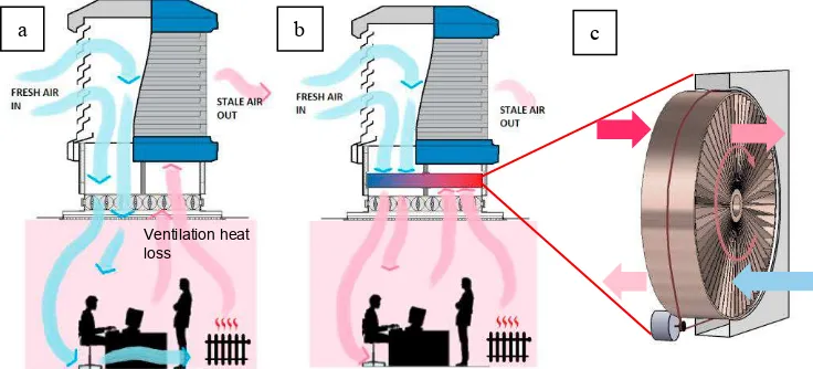
The government policy to reduce UK carbon emissions by at least 80% of the pre-1990 levels by 2050 is a major driving force in reducing the energy demand of the built environment [1]. A large percentage of the energy use is due to space heating which accounts for up to 40% of the total energy demand in both residential and service sector properties and other developed countries [2]. Hence, reducing the energy required to heat buildings domestic and commercial buildings presents one part of a solution to reach the goal of cutting carbon emission. Recently, natural ventilation techniques such as windcatchers were increasingly being employed in buildings for increasing the supply of fresh air and reducing the mechanical ventilation consumption [3]. Windcatchers were utilised in buildings in the Middle East for many centuries and their commercialisation had increased over the years [4, 5]. A windcatcher is divided into quadrants, which allow fresh air to enter as well as stale (used) air to escape irrespective of the prevailing wind direction (Figure 1a). The windcatchers provides fresh air driven by the positive air pressure on the wind-ward side, while exhausting stale air with the assistance of the suction pressure on the leeward side. Windcatchers also operate by a secondary action of the stack effect; the density of air decreases as the temperature increases, causing warmer air to rise and exit the windcatchers. In mild-cold climates such as in the UK, their use is generally limited to the summer, as shown in Figure 1. This is due to the potential for low incoming air temperatures to cause thermal discomfort to the occupants and the use of natural ventilation solutions will increase heat loss and lead to increased energy costs [6]. While by restricting the use of natural ventilation during winter months, the concentration of pollutants have been seen to rise above the accepted guideline levels, which can lead to poor mental performance and ill health [5, 6].
Recently, windcatchers have undergone considerable amount of research to better understand the effect of airflow through and over windcatchers as well as the ventilation rates that can be provided by these systems [7]. Further to this, attempts have been made to improve the thermal comfort that can be provided to occupants [8]. The work has been conducted through the use of CFD modelling as well as scaled wind tunnel testing and in some cases, in situ or field testing in order to understand the effects in a real-world environment [9].
Fig. 1. (a) standard windcatcher (b) passive heat recovery windcatcher (c) proposed passive heat recovery wheel
Though windcatcher cooling [10-12] has had more attention in the past, little work has been carried out in the area of heat recovery or heating incoming air in windcatchers. Shao et al. [13] noted that passive stack systems are designed without heat recovery which leads to large amounts of wasted heat. Woods et al. [14] looked at the use of windcatchers during the winter using air mixing techniques to dilute the incoming cool air with the internal air. This system increased the incoming air temperature, thereby negating the heat demand whilst maintaining adequate pollutant levels but required very strict building design and control systems. Though this area of research is expanding with more teams exploring the potential of heat recovery in passive ventilation systems, little work has been performed on the use of the rotary thermal wheels specifically in natural ventilation. This is due to the high pressure drop across the
a b c
[image:3.544.92.460.393.560.2]rotary wheel which can impede the flow of air through the natural ventilation system. Rotary thermal wheels provide heat recovery at a high efficiency, even when compared to other heat recovery technology. The potential for energy savings using a rotary thermal wheel coupled with a passive ventilation system such as a wind tower are high. The lack of current research exploring a system similar to this demonstrates a key gap in existing knowledge.
To improve the year-round capabilities of windcatcher systems to enable consistent use during cooler months, a retrofit heat recovery system is desirable. This study introduces and discusses the potential of this concept using CFD analysis and wind tunnel experimental for validation. The concept is to attach a redesigned rotary heat recovery wheel system at the bottom channel of a windcatcher, as shown in Figure 1b. Using the properties of the thermal wheel as a heat exchanger, the thermal energy in the internal exhaust air is recovered to the incoming air. This concept raises the incoming air temperature. By raising the temperature of the incoming air from the windcatcher, adequate year-round ventilation is maintained and during the heating season, energy demand for heating systems is reduced.
2.Methodology
2.1.Numerical modelling
ANSYS Fluent 18 software was used to conduct the steady-state Reynolds averaged Navier–Stokes equation) which employed a control-volume-based technique for solving the flow equations. The standard k-e turbulence model was used, which is a well-established method in research on windcatcher natural ventilation [4]. Second-order upwind scheme was used to discretised all the transport equations. The numerical code used the semi-Implicit method for pressure-linked equations algorithm for the velocity-pressure coupling of the computation. The governing equations are not repeated here but available in the ANSYS User guide. The flow domain representation of the geometry of the windcatcher and location of set boundary conditions are shown in Figure 2a. A 5 x 5 x 10 m3 enclosure was created to simulate the velocity of the outdoor wind. Furthermore, the model of the 1 x 1 m2 windcatcher was integrated to a test room located beneath it. The test room with an internal volume of 3 x 3 x 5 m3 represents a small classroom [7]. windcatcher was modelled with seven louvres angled at 45°. The wind tower was assumed to be supplying at 100% (fully open), therefore the volume control dampers was not added to the model. The rotary heat recovery wheel was connected below the windcatcher as a separate part. Unlike previous works, the rotary heat recovery wheel was modelled explicitly with radial plates instead of using porous zone method. A non-uniform mesh was applied to the volumes of the computational model. The computational mesh of the windcatcher and test room model is shown in Figure 2b. The mesh was refined around critical areas of interests in the simulation. Several meshes were generated to investigate the solution independency from the mesh. The mesh was refined (mesh sizes ranging from 2.8 to 7.4 million elements) until the posterior estimate error became insignificant between the number of elements and the posterior error indicator (supply velocity). The discretisation error was found to be the lowest at over 7.4 million elements.
Fig. 2. (a) Computational domain (b) mesh design
The rotation of the rotary heat recovery wheel was modelled using frame motion in ANSYS Fluent. The mesh motion of the rotary heat recovery wheel was orientated at the centre point and vertical axis of the wheel; this ensured that the volume rotated around the centre point at the required speeds of 15rpm (1.57 rads/s). The material of the heat recovery wheel was set to copper. The CFD analysis was performed at various outdoor wind speeds (0 - 5 m/s). The pressure outlet was set to 0 Pa (atmospheric). For the analysis of the windcatcher, the external air temperature was set
[image:4.544.69.452.470.598.2]3128 John Calautit et al. / Energy Procedia 158 (2019) 3125–3130
to 283 K to simulate a cold outdoor environment. This was chosen as it represented the average annual air temperature in the UK according to the UK Met Office. The floor was set as a heat source with a heat flux of 75 W/m2 to simulate the internal heat gains (occupants and equipment) in a teaching space.
2.2.Experimental wind tunnel testing
[image:5.544.44.492.288.413.2]The experimental investigation was conducted in a closed-loop wind tunnel [15]. The size of the test section was 0.5 x 0.5 m2 and 1m length (Fig 3). A 1:10 scale model of the windcatcher with heat recovery wheel was used in the experimental study. The creation of an accurate scaled model was essential for the study; therefore, the windcatcher was constructed using 3D printing. The scale of the model of the windcatcher was selected to maintain, as close as possible, equality of model and prototype ratios of overall dimensions to the important meteorological lengths of the simulated wind. The rotary heat recovery wheel was designed to be 80mm in diameter with a depth of 20mm and porosity of 70%. The rotary heat recovery wheel was held in place in the casing by using supports which did not interfere with the rotation. In order to achieve the required rotation speed for the wheel, a rotation shaft was fitted through the test section vertically which connected to a DC motor underneath the test section. The rotation shaft was kept as thin as possible in order to prevent the flow being affected. The scale model of the windcatcher produced a maximum wind tunnel blockage of 4.8%. The model of the windcatcher was connected to a 0.5 x 0.5 x 0.3 m3 test room, mounted underneath the test section.
Fig. 3. Experimental wind tunnel testing of the passive heat recovery windcatcher
In order to assess the air flow characteristics through the windcatcher with the rotary heat recovery wheel, nine predetermined points within the room model were used for the measurement of the air velocity (Figure 4b). The nine points within the room model were chosen in order to give an equal spread of measurement points and to ensure that the mixture profile of the air could be monitored. The hot wire probe (Testo 425) gave velocity measurements with uncertainty of ±1.0 % rdg. at speeds lower than 8 m/s.
4. Results and Discussion
To validate the CFD model against the experimental model, the percentage error between the two data sets must be to an acceptable level. In addition to percentage error as an indicator of correlation, identifying equal trends in both sets of data is important to validate the CFD model. To determine the accuracy of the CFD model in relation to the wind tunnel model, first a comparison of the quantitative data was taken to calculate the numerical accuracy. The air velocity at the building model mid-height was calculated at each of the nine measurement points for the three different external air velocities. Figure 4a shows a comparison between the experimental and CFD results of the velocity measurements. This comparison showed a low difference range and the trends were to be in a good agreement. Average error across the points was 7.46%. It should be noted that the boundary conditions in the CFD model were kept as similar as possible to those in the experiment, minimising the error which could be caused.
Four-sided windcatcher Heat recovery
wheel
Motor
Fig. 4. (a) Comparison between CFD and experiment values of air velocity (b) measurement points at a height of 150mm in the test room.
Figure 5a shows the temperature contours of the cross-sectional plane in the test room model. As observed, the addition of heat recovery had a positive effect on the indoor air temperature, raising the incoming fresh air to 284-285K when the outdoor wind speed and temperature are 3m/s and 283K. It is worth noting that the temperature difference seen in the inflow and outflow of the wind tower. On the inlet stream of the wheel, the air temperature is at 283 K. On the outlet stream of the wheel, the air temperature is 290 K due to the heating effect of the floor area. This suggests that if the increased temperature in the outlet stream can be recovered and transferred to the inlet stream, the inlet temperature would reduce the demand on any heating system used. Further to this, the inlet air temperature was set at 283 K which is higher than average winter outdoor air temperature during the recorded in the UK between 1981 and 2010 of 277–279 K, meaning that the exhaust stream temperature would be even higher than the inlet stream temperature, giving great potential for thermal energy recovery and transfer.
[image:6.544.43.493.75.195.2]
Fig. 5. Cross-sectional contour planes of (a) air temperature (b) air velocity with the outdoor wind speed and temperature at 3m/s and 283K Figure 5b illustrates the contours of velocity in the vertical plane drawn from the middle of the room which is aligned with the direction of the flow and contains the centre of the windcatcher. The airflow that entered the windcatcher via the 45˚ louvers was deflected upwards while the lower side of the flow was in reverse which formed a small recirculation region. The flow slightly accelerated as it turns sharply inside the 90° corner. Although reduction in speed was observed downstream of the heat recovery device, it did not impede the ventilation rate of the wind catcher. A column of fast moving air enters the space, where the airstream hit the floor of the room and circulated inside the structure and exited the wind catcher exhaust. Large recirculation region was observed at the leeward side of the wind tower. Figure 6a shows the effect of varying the outdoor wind speed on the indoor air temperature for standard windcatcher and windcatcher with heat recovery. As expected, the higher the outdoor wind speed, the lower resultant air temperature inside the room. The rate at which the internal temperature falls as the inlet velocity increases was of significance. A more substantial temperature increase was seen from 2 m/s to 3 m/s (2-4 K supply air temperature reduction) outdoor wind speed, than from 3 m/s to 5 m/s (1-2 K supply air temperature reduction). Figure 6b shows the effect of varying the outdoor wind speed on the average indoor air velocity.
0 0.2 0.4 0.6 0.8 1
Point 1 Point 2 Point 3 Point 4 Point 5 Point 6 Point 7 Point 8 Point 9
V
e
lo
c
it
y
(
m
/s
) CFD
Experiment
1 2 3
4 5 6
7 8 9
a b
[image:6.544.56.486.347.506.2]3130 John Calautit et al. / Energy Procedia 158 (2019) 3125–3130
Fig. 6. Effect of varying external wind speeds on average (a) indoor temperature (b) indoor velocity
5. Conclusion and Future Work
In this study, the air flow through a windcatcher with a rotary heat recovery wheel was investigated using CFD modelling. It has been shown in previous work that windcatchers are capable of delivering the guideline levels of ventilation into a room, therefore the rotary wheel should not reduce the air supply rate to unsuitable levels to provide adequate ventilation to be an effective system. The numerical modelling was validated against experimental models tested in a closed-loop wind tunnel. The comparison between the CFD and experimental model showed a good correlation between the two sets of data. Results showed that the addition of heat recovery had a positive effect on the indoor air temperature, raising the temperature between 1-4 K depending on the outdoor wind conditions. According to WBCSD [2], a recovery of 3 K from the exhaust stream to the inlet stream could generate energy savings up to 20% in heating costs. This shows that the concept has significant potential to be developed further, whereby the heat transfer properties of the system can be investigated and tested on a larger scale.
Acknowledgement
The authors would like to acknowledge the support given by the University of Sheffield. The technology presented here is subject to an international patent application (WO2016024073A1).
References
[1] O’Connor D, Calautit JK, Hughes BR, A review of heat recovery technology for passive ventilation applications. Renewable and Sustainable Energy Reviews, 2016;54:1481-1493.
[2] World Business Council for Sustainable Development 2008.
[3] Calautit JK, Hughes BR, Nasir DSNM, Climatic analysis of a passive cooling technology for the built environment in hot countries. Applied
Energy 2017;186:321-335.
[4] Hughes BR, Calautit JK, Ghani SA, The Development of Commercial Wind Towers for Natural Ventilation: a review. Applied Energy
2012;92:606-27
[5] Nejat P, Calautit JK, Majid M, Hughes BR, Zeynali I, Jomehzadeh F, Evaluation of a two-sided windcatcher integrated with wing wall (as a
new design) and comparison with a conventional windcatcher. Energy and Buildings 2016;126:287-300.
[6] Calautit JK, Hughes BR, Wind tunnel and CFD study of the natural ventilation performance of a commercial multi-directional wind tower. Building and Environment 2014;80:71-83.
[7] Calautit JK, O’Connor D, Hughes BR. Determining the optimum spacing and arrangement for commercial wind towers for ventilation
performance. Building and Environment 2014;82:274-287.
[8] Hosseini SH, Shokry E, Hosseini AJ, Ahmadi G, Calautit JK, Evaluation of airflow and thermal comfort in buildings ventilated with wind
catchers: Simulation of conditions in Yazd City, Iran. Energy for Sustainable Development 2016;35:7-24.
[9] Nejat P, Calautit JK, Majid MZ, Hughes BR, Jomehzadeh F, Anti-short-circuit device: A new solution for short-circuiting in windcatcher and
improvement of natural ventilation performance. Building and Environment 2016;105:24-39.
[10] Chaudhry HN, Calautit JK, Hughes BR, Computational analysis of a wind tower assisted passive cooling technology for the built
environment. Journal of Building Engineering 2015;1:63-71.
[11] Calautit JK, Chaudhry HN, Hughes BR, Ghani SA, Comparison between evaporative cooling and heat pipe assisted thermal loop for a
commercial wind tower in hot and dry climatic conditions. Applied Energy 2013;101:740-755.
[12] Calautit JK, Hughes BR, Shahzad SS, CFD and wind tunnel study of the performance of a uni-directional wind catcher with heat transfer
devices. Renewable Energy 2015;83:85-99.
[13] Shao L, Riffat SB, Gan G, Heat recovery with low pressure loss for natural ventilation. Energy and Buildings 1998;28:179-184.
[14] Woods AW, Fitzgerald S, Livermore S, A comparison of winter pre-heating requirements for natural displacement and natural mixing
ventilation. Energy and Buildings 2009;41(12):1306-1312.
[15] Calautit JK, Chaudhry HN, Hughes BR, Sim LF, A validated design methodology for a closed-loop subsonic wind tunnel. Journal of Wind
Engineering and Industrial Aerodynamics 2014;125:180-94. 280
285 290 295 300
2 3 4 5
In d o o r te m p e ra tu re ( K )
Outdoor wind velocity (m/s) no HR with HR 0 0.1 0.2 0.3 0.4
2 3 4 5
A v e ra g e i n d o o r w in d s p e e d ( m /s )