Faculty of Engineering & Surveying
Development of a Laser Pointer Mouse
A dissertation submitted by
Mr Anthony Gibbons
in fulfilment of the requirements of
ENG4112 Research Project
towards the degree of
Bachelor of Engineering (Software Engineering)
Submitted: October, 2010
Abstract
This dissertation is a comprehensive report on the initial stages of the development of
a laser pointer mouse for use in computer driven projector based presentations. The
initial aim of the project was to develop software that enables the user to control a
computer using only a webcam and laser pointer in a presentation environment.
The outcome of comprehensive background studies in this dissertation has found the
existence of projects with working laser pointer mouse devices, but none of which had
any of the features proposed for this project, especially with tracing a circle around an
object to be clicked and auto-calibration.
This system in this project uses the DirectShow applications programming interface in
Microsoft Windows to interface with the camera, obtain a frame and detect through
the use of a “high-pass filter” the presence of the laser. The system is then able to
return the position of the laser in terms of its corresponding pixel position. Reliable
error tolerant laser detection, calibration, circle clicking and system integration was
Faculty of Engineering and Surveying
ENG4111/2 Research Project
Limitations of Use
The Council of the University of Southern Queensland, its Faculty of Engineering and
Surveying, and the staff of the University of Southern Queensland, do not accept any
responsibility for the truth, accuracy or completeness of material contained within or
associated with this dissertation.
Persons using all or any part of this material do so at their own risk, and not at the
risk of the Council of the University of Southern Queensland, its Faculty of Engineering
and Surveying or the staff of the University of Southern Queensland.
This dissertation reports an educational exercise and has no purpose or validity beyond
this exercise. The sole purpose of the course pair entitled “Research Project” is to
contribute to the overall education within the student’s chosen degree program. This
document, the associated hardware, software, drawings, and other material set out in
the associated appendices should not be used for any other purpose: if they are so used,
it is entirely at the risk of the user.
Prof F Bullen
Dean
Certification
I certify that the ideas, designs and experimental work, results analyses and conclusions set out in this dissertation are entirely my own effort, except where otherwise indicated and
acknowledged.
I further certify that the work is original and has not been previously submitted for assessment in any other course or institution, except where specifically stated.
Anthony John Gibbons
Student Number: 0050009494
Signature
Acknowledgments
I would like to especially thank Dr. John Leis, my supervisor, for his continued
encour-agement and support not just during this project, but also through my entire program.
I would like to thank the members of my family for being patient and understanding
during the challenging undertaking of this project, and I would also like to thank St
Patrick’s College, Mackay for providing me with the lab environment I needed for
certain aspects of this work.
Mr Anthony Gibbons
University of Southern Queensland
Contents
Abstract i
Acknowledgments iii
List of Figures xv
List of Tables xvii
Chapter 1 Introduction 1
1.1 Project Aim . . . 2
1.2 Specific Objectives . . . 3
1.3 Overview of the Dissertation . . . 4
Chapter 2 Background 6 2.1 Chapter Overview . . . 6
2.2 Existing Presentation Control Devices . . . 6
2.2.1 Wireless Presenters . . . 6
2.3 The required qualities of the solution . . . 9
2.3.1 User Friendliness . . . 9
2.3.2 Performance . . . 11
2.3.3 Cost . . . 12
2.3.4 Availability . . . 13
2.4 The need for the laser pointer mouse . . . 13
2.4.1 The user friendliness of the Laser Pointer Mouse . . . 14
2.4.2 The performance of the Laser Pointer Mouse . . . 15
2.4.3 The cost and availability of the Laser Pointer Mouse . . . 15
2.5 Current Developments on the Laser Pointer Mouse Concept . . . 16
2.5.1 Patents . . . 16
2.5.2 The current existence of the device . . . 17
2.5.3 A very brief overview of the main requirements of the laser pointer mouse . . . 18
2.5.4 How existing devices meets the requirements for this project . . 19
2.5.5 Other similar computer vision based interaction technologies . . 21
2.6 Chapter Summary . . . 24
Chapter 3 Methodology and Approaches 25 3.1 Chapter Overview . . . 25
CONTENTS vi
3.3 The obvious tasks . . . 26
3.3.1 Components of this project . . . 27
3.4 The overall system architectural approach . . . 27
3.4.1 Calibration Subsystems . . . 28
3.4.2 Circle Clicking Subsystem . . . 29
3.4.3 Laser Detection Subsystem . . . 30
3.4.4 System components meeting the specifications . . . 31
3.5 The work breakdown structure . . . 31
3.6 Top Level WBS explained in more detail . . . 32
3.6.1 Setting up and preparation . . . 32
3.6.2 Interfacing the camera . . . 34
3.6.3 Finding the position of the laser point . . . 35
3.6.4 Calibrating the position of the laser with the screen . . . 38
3.6.5 Circle clicking . . . 41
3.6.6 Slide Navigation . . . 43
3.6.7 Automatic calibration . . . 44
3.6.8 System integration into one standalone package . . . 45
3.6.9 Reporting . . . 46
3.6.10 The Complete Work Breakdown Structure . . . 47
3.7 Laser Pointer Mouse Project Time line . . . 49
3.8 Assessment of Consequential Effects . . . 50
3.8.1 Introduction . . . 50
3.8.2 Sustainability . . . 50
3.8.3 Safety . . . 52
3.8.4 Ethical . . . 53
3.8.5 Conclusion . . . 55
3.9 Risk Assessment . . . 56
3.9.1 Identifying the risks in this project . . . 56
3.9.2 Risk Quantification . . . 58
3.9.3 Risk Control . . . 60
3.10 Chapter Summary . . . 62
Chapter 4 Setting Up and Preparation 63 4.1 Chapter Overview . . . 63
4.2 Hardware Selection . . . 64
4.2.1 Overview . . . 64
4.2.2 The Selection of the Webcam . . . 64
4.2.3 The Selection of the Laser Pointer . . . 66
4.2.4 Summary . . . 67
CONTENTS viii
4.3.1 Overview . . . 68
4.3.2 Software Requirements . . . 68
4.3.3 OpenCV . . . 69
4.3.4 Existing Webcam Interface System Using DirectShow . . . 69
4.3.5 The Chosen Webcam Interface API . . . 70
4.3.6 Summary . . . 71
4.4 Test Bench . . . 71
4.4.1 Overview . . . 71
4.4.2 Requirements for Testing . . . 71
4.4.3 The Bedroom Lab . . . 72
4.4.4 School Classroom . . . 73
4.4.5 Summary . . . 74
4.5 The Integrated Development Environment . . . 74
4.5.1 Overview . . . 74
4.5.2 Compiler To Be Used . . . 74
4.5.3 Compilation Method . . . 74
4.5.4 Make for Windows . . . 75
4.5.5 LCC Compiler For Windows . . . 75
4.5.6 Text Editor . . . 76
4.5.8 Summary . . . 77
4.6 Chapter Summary . . . 77
Chapter 5 Interfacing the Webcam 79 5.1 Chapter Overview . . . 79
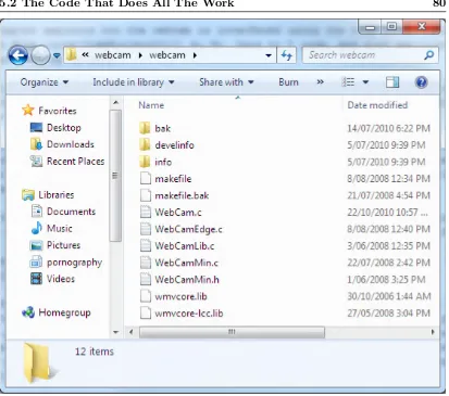
5.2 The Code That Does All The Work . . . 80
5.3 Overview of the WebCam interface Application . . . 81
5.3.1 Overview . . . 81
5.3.2 The Usefulness Of The Application . . . 82
5.3.3 Summary . . . 83
5.4 How the Application Works . . . 83
5.4.1 Overview . . . 83
5.4.2 The Main Function and what it does . . . 84
5.4.3 The Callback Function . . . 86
5.4.4 Summary . . . 86
5.5 Interface to the Webcam . . . 87
5.5.1 Overview . . . 87
5.5.2 Investigation Approach . . . 87
5.5.3 The ImageBuffer Object . . . 87
5.5.4 The Starting Point . . . 88
CONTENTS x
5.5.6 High Level Webcam Interface Subsystem . . . 89
5.5.7 Summary . . . 89
5.6 The ImageBuffer . . . 90
5.7 The ProcessFrame Function . . . 91
5.7.1 Overview . . . 91
5.7.2 The For Loops . . . 91
5.7.3 The Image Processing . . . 92
5.7.4 Summary . . . 93
5.8 Chapter Summary . . . 93
Chapter 6 Developing Laser Detection 94 6.1 Chapter Overview . . . 94
6.2 The Work Breakdown Structure . . . 95
6.3 Laser Detection in Other Projects . . . 95
6.4 Colour Filtering . . . 96
6.4.1 Overview . . . 96
6.4.2 Looking for Red . . . 96
6.4.3 Implementing the Red Filter . . . 96
6.4.4 Compiling Project . . . 97
6.4.5 Results . . . 97
6.4.7 Summary . . . 100
6.5 The High Pass Filter Method . . . 100
6.5.1 Overview . . . 100
6.5.2 The High Pass Filter . . . 100
6.5.3 Implementing The High Pass Filter . . . 101
6.5.4 Initial Test of the High Pass Filter . . . 102
6.5.5 Testing the Presence of the Laser . . . 103
6.5.6 Summary . . . 104
6.6 Creating a Controlled Environment . . . 104
6.6.1 Overview . . . 104
6.6.2 Problems with Other Light Sources . . . 104
6.6.3 Reducing Light Sources . . . 105
6.6.4 A really sensitive webcam . . . 105
6.6.5 Testing Laser in Controlled Environment . . . 106
6.6.6 System Expectations . . . 107
6.6.7 Summary . . . 107
6.7 Detecting Pixel Location . . . 108
6.7.1 Overview . . . 108
6.7.2 Implementation of Laser Location Detection . . . 108
CONTENTS xii
6.7.4 Outputting the Location of the Laser . . . 109
6.7.5 Testing Laser Location Detection Approach . . . 109
6.7.6 Testing Laser Location Detection . . . 110
6.7.7 Summary . . . 112
6.8 Initial Laser Detection System Performance . . . 112
6.8.1 Overview . . . 112
6.8.2 Problems with Current System . . . 113
6.8.3 Measuring the Performance of the System . . . 113
6.8.4 Approach . . . 113
6.8.5 Implementation of the Code . . . 114
6.8.6 Program Output . . . 118
6.8.7 Summary . . . 118
6.9 Chapter Summary . . . 118
Chapter 7 Results and Discussions 119 7.1 Chapter Overview . . . 119
7.2 Colour Filters . . . 119
7.3 The High Pass Filter . . . 120
7.4 Laser Detection Performance . . . 120
7.4.1 Laser Movement . . . 120
7.4.3 Detection Rate . . . 123
7.5 Problems With the Current Approach . . . 124
7.6 Proposed Improvements . . . 124
7.6.1 Characteristics of the Laser Spot . . . 124
7.6.2 Method of Detection . . . 125
7.6.3 Chapter Summary . . . 127
Chapter 8 Conclusions 128 8.1 Introduction . . . 128
8.2 Existing devices . . . 128
8.3 Laser Detection . . . 129
8.4 Motion Tracking . . . 129
8.5 Work Not Completed . . . 130
8.6 Further Work . . . 130
8.7 Final Conclusion . . . 131
References 132
Appendix A Project Specification 136
Appendix B Project Timeline 139
CONTENTS xiv
C.1 DSE Prices on Webcams . . . 154
C.2 Logitech Webcam C200 Specifications . . . 158
C.3 Logitech Webcam C910 Specifications . . . 160
Appendix D Source Code Files 161 D.1 Webcam.c Source . . . 162
D.2 WebCamLib.c Source . . . 199
D.3 WebCamMin.h Source . . . 224
D.4 Makefile . . . 253
Appendix E Program Output 257 E.1 Laser Motion Data Program Output . . . 258
List of Figures
3.1 Laser pointer mouse overall system design showing the various subsystems 28
3.2 Laser detection subsystem with its three layers . . . 30
3.3 The effects of Keystone (Wikipedia 2010d) . . . 39
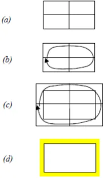
3.4 Possible circle detection approach (Wikipedia 2010d) . . . 41
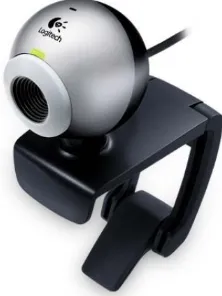
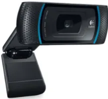
4.1 The Logitech Webcam C200 chosen for this project . . . 64
4.2 High performance Logitech Webcam C910 . . . 65
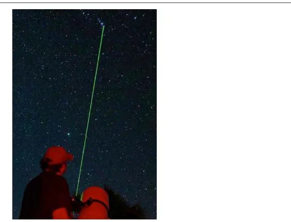
4.3 A class 3R green laser pointer used for aligning an astronomical telescope at the target star. These beams are clearly visible, unlike the red laser pointer . . . 66
4.4 As can be seen in this figure, the green laser is significanlty brighter than the red laser! . . . 67
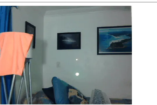
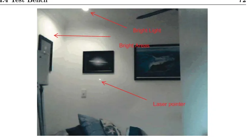
4.5 In this figure, the bright areas generated by the lighting in the room are visible, and can be compared with the laser dot . . . 72
5.1 Files of the webcam interface system . . . 80
LIST OF FIGURES xvi
6.1 Red Filter Applied . . . 98
6.2 Presense of the Laser . . . 98
6.3 Laser not Visible . . . 99
6.4 Levels in Adobe Photoshop . . . 101
6.5 Application of the High Pass Filter . . . 102
6.6 Laser captured and clearly visible! . . . 103
6.7 Exposure compensation causes laser trails . . . 103
6.8 Laser pointed at the bottom left of the image, the result of (25,17) ap-pears correct. . . 110
6.9 Laser pointed at the top left of the image, the result of (26,467) appears correct. . . 111
6.10 Laser pointed at the bottom right of the image, the result of (621,17) appears correct. . . 111
6.11 Laser pointed at a random spot , the result of (451,111) appears correct. 112 7.1 The motion of the laser is indicated by the red line . . . 121
Chapter 1
Introduction
The use of modern slide show presentations to communicate to an audience is becoming
increasingly popular. The equipment used to conduct these, what is commonly referred
to as “power point presentations”, is typically a computer running presentation software
such as Microsoft Power Point, which is connected to a data projector that projects
what is on the computer screen to a large screen that everyone in the audience can see.
In the majority of the situations, the person or person’s conducting the presentation
is commonly confined to where the computer is in order to control the presentation.
This prevents the presenter from walking around the room and communicating more
effectively with the audience. One way that this problem is solved, is through using
wireless presenters, which are portable devices much like a remote control that enables
the presenter to move between the slides remotely from anywhere in the room by
pressing typical navigation buttons such as next and previous. Some more dedicated
wireless presenters have a little joystick on it that is capable of controlling the mouse
in what can be a slow and cumbersome experience for less experienced users.
The use of laser pointers for pointing things out on the screen is also becoming
increas-ingly popular as many wireless presentation devices have these integrated in them. But
laser pointers are more commonly purchased as small separate devices that uses button
style batteries and have become very cheap over the last ten years, dropping from one
pointers but also for fun, and is sometimes even used to amuse pets.
If the laser pointer was able to be used as a mouse, and the presenter can control
the mouse from anywhere in the room and even click on things, then it would greatly
reduce the need for having to be near the computer, and also make interaction with
the computer’s mouse from a distance more natural.
A small collection of people have been able to produce such as system with various
capabilities, most of these systems requiring a calibration process and also the use
of dwell clicking to click on items on the screen. This makes it hard to differentiate
between double clicking, single clicking and left and right clicking.
One way of solving this problem is to trace a circle around the object to be clicked;
anti-clockwise for left clicking, and clockwise for right clicking, and possibly even a
triangle for double clicking which would speed up the process of interaction.
To have a laser pointer mouse system that the user can just connect up and use with
an ordinary laser pointer, and using a web-cam to detect the laser spot on the screen,
without the need for calibration would be an enhancement of what has already been
achieved.
1.1
Project Aim
The aim of this project was to develop software that can enable a user to control
the computer of a projected presentation using only a basic laser pointer and webcam
exclusively.
In order to enhance what has already been achieved by others, this project also aims
to implement a system that can automatically calibrate, as well as enable the user to
1.2 Specific Objectives 3
1.2
Specific Objectives
• Investigate the concept of a laser-pointer mouse for use with data projectors by
investigating literature on the topic, patents, and possible existing commercial
devices.
Obviously there is no point in ‘reinventing the wheel’, and so it would be
ap-propriate to do some research into what other’s have already been able to do
with regard to a laser pointer mouse. Then use some of their ideas to assist in
achieving the outcomes of this project and also perhaps build on to what they
have achieved.
• Investigate user interface technology and the need for such a device in the
commer-cial market or specommer-cialized markets such as to aid persons with certain disabilities.
In doing the above, it will be useful to know what other types of devices or systems
exist that makes it easy for people to interact with projected presentation other
than using the computer, and to determine whether the laser pointer mouse could
make it easier for people with disabilities.
• Investigate color point detecting algorithms using a webcam-based vision system,
and determine if the recognition of a laser spot can be performed in real-time.
• Investigate motion-tracking algorithms for the laser spot which account for the
variability of the pointer motion, including circle-tracing to emulate mouse
click-ing.
– If it is possible to track the laser pointer and determine around which item a
circle has been traced, ways of detecting clockwise and anti-clockwise motion
as well as even a triangle would be aimed for in order to make it possible to
perform left, right and double clicking as well.
– An additional feature will also be attempted that will allow the user to flash
the laser on either side of the screen that will tell the system whether to
move to the next slide or to move to the previous slide.
– Another feature will be aimed for that will enable the user to perform a
ei-ther interaction mode, or pointing mode to prevent the user from making
accidental clicks.
• Develop prototype code for testing the above algorithms, and assess the feasibility
of the concept.
Efforts will be made to develop code that can enable the laser to be used as a
mouse, at least in its ability to determine the location of the laser on the screen and
move the mouse there as well as being able to click on the item. This prototype
code will be demonstrated in this dissertation, but due to time constraints, an
independently working system may not be completed.
• Investigate the requirement for calibration of the pointer system, and implement
prototype test code.
An attempt will be made at developing a system that is capable of auto-calibration.
This means that the user can start using the laser pointer mouse straight away
after connecting the camera and starting up the software.
As time permits:
• Integrate the code into a system which can interface with the Windows API in
order to inject mouse events into the system.
• Integrate into a complete standalone application which can use the laser as a
mouse.
1.3
Overview of the Dissertation
This dissertation is organized as follows:
Chapter 2 Introduces the concept and delivers a comprehensive literature review of
1.3 Overview of the Dissertation 5
Chapter 3 The development of the methodology and approaches is covered in this
Chapter as well as the assessment of risks and consequential effects.
Chapter 4 This chapter describes the processes that was involved in setting up the
working environment for this project, as well as setting up the integrated
devel-opment environment.
Chapter 5 This chapter explains the work done on developing the usage of the
web-cam interface so that the software can retrieve a frame for processing.
Chapter 6 This chapter explains the development of the laser detection algorithm
and shows some of the outputs generated by the software.
Chapter 7 This chapter discusses the results and covers some of the proposed
im-provements for the laser detection system.
Chapter 8 This chapter concludes the project and suggests future directions for the
Background
2.1
Chapter Overview
This chapter explores some existing technologies that are being used to control
presen-tations. It also provides a comprehensive review of some of the existing laser pointer
mice devices that have been developed and provides a brief explanation of their
func-tion as well as what is perceived to be the good and bad aspects of each, and which of
the good aspects could be included and enhanced upon in this project.
2.2
Existing Presentation Control Devices
Currently projected presentations can be controlled by a variety of devices other than
the mouse and the keyboard. These have been found to fall broadly into two categories;
wireless presenters and interactive white boards.
2.2.1 Wireless Presenters
Wireless presenters are commonly in the form of a device similar to a remote control;
2.2 Existing Presentation Control Devices 7
Most of them contain the typical buttons needed to control the presentation such as the
next and previous buttons for navigating slides. One such example is the Professional
Presenter R800 (Logitech 2010c) which is one of the many wireless presenters developed
by Logitech. Other more expensive devices even has a way of controlling the mouse of
the computer such as the Targus Basic Presenter (TechBuy 2010). And then there are
other designs such as the Wireless Notebook Presenter Mouse 8000 (Microsoft 2010b)
developed by Microsoft that is basically a wireless mouse with presentation controls
underneath. The mouse is wireless so all the presenter needs to do is find a flat surface
nearby to use the wireless mouse in the normal way to control the presentation remotely
within the theatre.
2.2.2 Interactive White boards
The other method of controlling the presentation is in the form of an interactive white
board which in most cases looks like an ordinary white board used in class rooms.
These white boards have the added ability of the user being able to use the white board
as a touch screen when the screen of the computer is projected onto it using a data
projector. This enables the user to control the computer by touching the white board
where various interactive elements such as menu items and buttons are projected onto
from the computer. In most cases the white boards are connected to the computer either
wirelessly or physically using the Universal Serial Bus (USB) interface. Commonly these
boards have a grid of copper wires behind them that are joined together and eventually
connected to the computer which sends the signal of where the user has touched the
screen that the computer can use to perform interactive events (Nan Wodarz October
2005).
Usually at the start of the setup between the computer and the white board some
sort of a calibration process has to be performed in order to allow the device driver
software on the computer to determine the correct pixel coordinates of where the user
has touched it. Typically the software at the start displays a set of markers on the
board that the user must physically touch so that the computer can understand which
points on the white board corresponds to certain critical points on the computer screen,
these points the software can calculate the corresponding pixels on the computer screen
from the point pressed on the white board so that the user can accurately interact with
the computer.
Types of Interactive White boards
Generally there are three categories that interactive white boards belong to. The first is
a touch sensitive membrane that consists of two layers of flexible surfaces with a small
gap in between the two (Nan Wodarz October 2005). When the user touches this two
layered surface a signal is generated and sent to the computer that tells it where on the
screen the user has touched it. This is similar to how an iPod Touch works (Wilson &
Crawford 2010).
The second type of interactive white board is the electromagnetic design which is similar
to the traditional white board in that it has a hard durable surface, but underneath
this surface is a grid of wires that that detects the signal that comes from a special pen
that transmits an electromagnetic signal (Nan Wodarz October 2005, Wikipedia 2010c)
The third type of interactive whiteboard is a little less dedicated than the last two
and the cheapest option. This is basically an ordinary white board that has been
upgraded with the inclusion of an ultrasound kit. The ultrasound kit uses scanners
that are mounted on the top corners of the board (Nan Wodarz October 2005),or can
also come in the form of a bar that is affixed on the top of the white board or even a
wall (Wikipedia 2010c). A special pen or pen housing is used to interact with the board
which is detected by the scanners which sends the coordinates back to the computer.
All three of these types of white boards have some sort of integrated circuitry attached
to them that allows for the detection of the position of a pointing device of some sort.
Another type of interactive white board solution that is very close to the functionality
of the laser pointer mouse is the use of a Nintendo Wii remote. Though they may be
considered a bit of a ”hack” they do work, and are based on sound electronic and optical
principals, invented originally by Johnny Chung Lee, PhD. in 2007 (Wikipedia 2010c).
2.3 The required qualities of the solution 9
(IR) camera on the front of the Wii remote control to capture and detect the IR pen in
front of the white board. The user simply uses this pen to interact with the computer
from the computer screen image projected on the white board.
The reason why this design is very close to the proposed laser pointer mouse is because
it uses a camera to detect the source of the infrared light at the tip of the IR pen relative
to the projected image of the computer screen. So some form if image processing needs
to be performed on the image captured by the camera in the Wii remote, similar to
what needs to be done with the location of the red dot on the screen produced with
the laser pointer.
2.3
The required qualities of the solution
The quality of the presentation control system can be assessed against four easily
un-derstood qualities such as user friendliness, availability, performance and cost. How
well this system performs in these four qualities will ultimately affect its popularity,
and the criteria that the device needs to meet in each of the four qualities will be
discussed below.
2.3.1 User Friendliness
For the system to be user friendly the user needs to be able to use the system requiring
very little training or need for reading instructions. To be able to interact with the
computer the actions to be performed needs to feel natural, and the installation of the
system needs to be quick and straight forward.
Wireless Presenters
Of all of the wireless presenter devices reviewed here, the Microsoft Notebook Presenter
Mouse 8000 (Microsoft 2010b)and other similar devices that come in the form of a
because of the fact that it is a mouse and can be used wirelessly up to 10 meters
away from the computer which enables the user to quickly and comfortably control the
mouse on the computer. It has the standard presentation control buttons underneath
such as next, previous, volume up and down and the fact that they can be customized
to control anything makes this device very flexible. And since it is a mouse, if the
user needs to control something else other than the presentation on the computer, the
mouse can be used wirelessly. This device also has a laser pointer integrated into it
which allows the user to highlight things on the screen. Because of this mouses plug
and play capabilities it is easy to install as well which adds to the user friendliness of
this device.
The next most user friendly device would be the wireless presenter remote controls that
have mouse control capabilities such as the Targus AMP17AP Wireless Presenter with
Cursor Control (Targus 2010). This device also comes with the presentation control
buttons and laser pointer but the reason why it is not as user friendly as the wireless
mouse presenter is because even though the mouse is controllable from this device, it is
more cumbersome and lower because of the small joystick. The joystick simply doesn’t
provide really fast and comfortable control over the mouse as the Microsoft Presenter
Mouse.
The other wireless presenter devices that do not contain mouse control would rank last
in terms of user friendliness because there is no control of the mouse whatsoever and
the user can only control the slides of the presentation.
Interactive White boards
From the information available in the literature about the interactive white boards
(Lee 2008, Nan Wodarz October 2005, Wikipedia 2010c), no matter what technology
they have they are all equally as user friendly because the user interacts with them in
the same way by using some sort of special pen and tapping the desired interaction
elements on the screen to interact with them. If the cost and availability wasn’t an
issue these systems would be more user friendly than the wireless presenters because
2.3 The required qualities of the solution 11
Other factors that will influence user friendliness will be the ease of installation and
calibration, but more detailed research into this is beyond the scope of this project
since its not concerned with the development of the laser pointer mouse.
2.3.2 Performance
When looking for good performance in this interaction system, attributes such as speed,
reliability and robustness is sought. Measuring the speed for this system is the same
as measuring the time it takes for the computer to react to a mouse click, or starting
up a program such as a word processor or game. So when the user selects a menu item
from the projected image on the white board, the time taken to react and cause the
menu to drop down compared with just a normal keyboard or mouse interaction for
the same item is an instance of the indication of the speed of the system. The closer
the reaction time is to a normal mouse or keyboard interaction the faster the system.
Reliability translates to the system being able to detect the correct position of where
the user is pointing at and not cause false positives, which is when the computer reacts
in a way that is not expected by the user such as the mouse pointer being purposely
positioned away from where the user is pointing.
Robustness is demonstrated when the system can handle unexpected inputs from the
user and not cause an error to occur, or the system to behave unexpectedly or even
crash.
Wireless Presenters Performance
Speed wise the wireless presenters would be higher performing than interactive white
boards but not by a really large amount. This is because the signals generated by the
wireless presenters do not require a large amount of processing of information and also
do not require to be calibrated unlike the interactive white boards. So their performance
would be similar to that of the wireless keyboard and mouse.
deter-mine the correct position of the mouse and point of interaction, the wireless presenters
although limited in capability, compared with interactive white boards are more reliable
and more robust because there is not much that can go wrong.
Interactive White boards Performance
Because of the calibration requirements of interactive white boards and delicate and
sophisticated methods of detection of interaction, the interactive white boards can be
seen as less reliable and robust than the wireless presenters but are capable of more in
terms of interactivity and user friendliness.
The speed of interaction with the interactive white boards would vary based on their
de-sign. The Nintendo Wii adaptation although the cheapest upgrade (Lee 2008, Wikipedia
2010c), would be the slowest and less reliable because of the use of a camera and the
need for the processing of the frames captured of the screen and the IR pen. On
the other hand, the touch sensitive membrane implementation of the interactive white
board should be the fastest and more reliable (but less robust) because of straight
signals being sent to the computer and no need for any further processing other than
calibrating the coordinates received. The most robust of the interactive white board
designs would be the ultrasonic upgrade and electromagnetic designs because their
de-tection mechanisms can be damaged by aggressive interaction such as with the touch
sensitive membrane design.
2.3.3 Cost
For the system to be cost effective means that generally any individual can acquire it
without much financial difficulty and can get hold of it fairly quickly such as within
one or two weeks based on an average low to middle income salary. So the sooner a
person can acquire the system without putting any real strain on finances, the more
cost effective the system is. Another costing factor to take into account is the cost of
upkeep such as the cost of replacing the batteries or lamps. When taking cost into
2.4 The need for the laser pointer mouse 13
and screen (although the screen is not absolutely essential).
The wireless presenters are obviously the cheapest option for controlling presentations
being around less than $200 some even as cheap as $50 (TechBuy 2010). The Microsoft
Wireless mouse presenter (Microsoft 2010b) would be the best because of its user
friend-liness and price. Although the associated running costs of wireless presenters would be
the cost of replacement batteries, but this is not really a serious issue.
Interactive White boards on the other hand are more expensive because of their
dedi-cated role and sophistication. The cheapest option for the interactive white board would
be the hack alternative of using the Nintendo Wii remote (Lee 2008, Wikipedia 2010c).
If one already have the remote as part of a Nintendo Wii entertainment system then a
working basic interactive white board can be achieved for very little cost, even cheaper
than the laser pointer mouse would be.
A dedicated interactive white board would be far more expensive. Eyo Technologies
retails a Panasonic UB-T760 Interactive Panaboard for nearly $2000 (Eyo 2010). So
this is definitely not an attractive method of interacting with the presentation for an
individual.
2.3.4 Availability
Availability means how quickly the system can be obtained and how easily it is
ac-cessible when money is not a factor. It is more likely to find a wireless presenter in
a department store in your everyday shopping center than an interactive white board
which would only be available from specialized suppliers or shops.
2.4
The need for the laser pointer mouse
The problem with the interactive white-board is that the presenter can’t move around
the room while talking to the audience and although there aren’t any real serious
laser pointer and being able to directly interact with the computer using this laser
pointer while using it as a normal pointer, just makes it easier and more convenient
than the wireless presenters. This project aims to develop a laser pointer mouse which
enables the presenter to use it as a pointer and an interaction device. The laser pointer
should be an ordinary red beam laser pointer and the detection device a relatively
cheap web cam.
2.4.1 The user friendliness of the Laser Pointer Mouse
Upon successful development of the laser pointer mouse the device will be very user
friendly in the sense that all the user has to do to navigate between slides is to flash
the laser on either side of the screen, on the left side for previous slide and on the right
side for next slide.
For the user to move the mouse or to interact with the computer, all the user has to do
is move the laser pointer to the desired button or menu item and trace a small circle
around the object. This will cause the computer to click on the object.
This is the quickest method of interaction compared with a wireless presenter because
if using the Microsoft Wireless mouse, the user has to find a flat surface first in order
to use the mouse (which may not look very professional in front of an audience), and if
using the Targus presenter, moving the mouse is even slower because of the interaction
with the joystick which is uncomfortable.
When compared with the interactive white board, it may seem that the interactive
white board would be more user friendly, but that means that the presenter needs to
stay near the screen and talk to the audience. With the laser pointer mouse, the screen
can be controlled from a distance allowing the presenter to move around the room and
talk to the audience.
The laser pointer mouse seems better than both the wireless presenters and the
inter-active white boards, but there might be a problem with using the laser pointer when
trying to click on things by tracing a circle. It is very hard to keep a laser pointer
2.4 The need for the laser pointer mouse 15
body, strong hands and some practice, and being nervous in front of an audience and
trying to use a laser pointer can be really difficult.
2.4.2 The performance of the Laser Pointer Mouse
Getting the computer to detect the position of the laser on the screen will require a fair
bit of image processing. One of the other factors that will influence the performance
of the laser pointer mouse as pointed out by Popovich (Popovich n.d.) in his paper on
the topic is the performance of the webcam. Low resolution and automatic brightness
control will make it very difficult to detect the laser and slow frame rates will make it
hard to keep track of laser movements in order to perform certain interactive actions
on the system.
The quality of the laser detection technique, the quality of the webcam and laser as
well as the processing ability of the computer will determine the performance, speed,
robustness and reliability of the laser pointer mouse.
2.4.3 The cost and availability of the Laser Pointer Mouse
For what this system will be able to do, it will be the most cost effective system because
laser pointers can be found at any electronic stores and can also be found on a lot of
these wireless presenters. The cost of a laser pointer ranges from $15 to about $50 at
places like Jaycar Electronics or Dick Smith Electronics and these stores are present in
most regional cities and some of the larger towns around Australia. The difference in
the quality of the laser spot between the cheapest and most expensive laser pointers is
negligible.
The other component that this system will need is a webcam. Webcams ranges from
about $20 to $100 and are more readily available than laser pointers at any computer
or electronics store. Generally the more expensive the webcam, the better the quality
of the image and the frame rate as well as manual controls and perhaps even the
availability of an Application Programming Interface (API) for the webcam to automate
So it is possible to have a laser pointer mouse put together for around $40 using the
cheapest and nastiest of laser pointers and webcams. But this will provide the ability
to remotely control the presentation from anywhere in the room without having to go
back to the computer.
2.5
Current Developments on the Laser Pointer Mouse
Concept
There have been a number of projects being conducted in the development of the laser
pointer mouse. During the research conducted for this project, three projects or systems
in particular stood out to be the closest to the requirements of this project. But other
projects have also been found to contain helpful information for the development of
this project. Two patents on the concept have also been found, but none of them have
anything about tracing a circle around interactive objects on the screen. Currently
there are no commercial devices that are being sold that are capable of working as a
laser pointer mouse. In the next section the findings of the research into these existing
projects will be summarized.
2.5.1 Patents
The two patents that have been found during the research are (Raynor 2007) and
(Finley 2003). Both of these patents are very generic and tries to cover everything that
could be developed using a laser pointer and a web-cam.
(Raynor 2007) is a European patent with the inventor being Jeffrey Raynor. This
patent proposes a laser pointer mouse system that uses a laser pointer and a web-cam,
but the laser pointer is a special one that has been modified to modulate it’s light
according to certain frequencies that dictates which button has been pressed. This
means that one can not use this system with an ordinary laser pointer, but need to get
hold of one that has been designed to output light signals so that clicking events can
2.5 Current Developments on the Laser Pointer Mouse Concept 17
The other patent that have been found is one by (Finley 2003) which is an American
patent with the inventor being Michael Cain Finley. This patent proposes or covers
a system that doesn’t require specialized hardware and can read the laser pointer of
any display device, not just the projector screen. This system also proposes to have
the ability to read hand writing patterns off the screen so that it can be determined as
character input signals like what one would get from the keyboard.
This is to prove that patents definitely exists and that the idea is not new. None of the
patents however covered tracing a circle around an object in order to be able to click
it and there is also nothing mentioned about being able to ’auto-calibrate’ the system.
2.5.2 The current existence of the device
A lot of interesting work on the concept of using a laser pointer as a mouse has been
done by various groups and individuals. Some of these systems developed perform
really closely to the requirements of the laser pointer mouse for this project, with the
exception of being able to circle objects on the screen in order to be able to click on
them. One of the laser pointer mice that have been developed was developed by a
team of four people from the Saha Institute of Nuclear Physics (Atul Chowdhary n.d.)
the principal author of the paper being Atul Chowdhary. This particular system uses
a red filter in front of its camera to make it easier to detect the laser on the screen
and detects the laser at the blue layer of the resulting image. This system however
like most of other systems developed requires manual calibration before it can be used
effectively.
Richard de Bruijn (de Bruijn 2008) from Eindhoven University of Technology developed
a system that is capable of automatically calibrating and uses hue, saturation and value
detection methods to detect the laser which means that this system is not limited to
having a physical filter in front of the camera.
Another system that matches closest to the requirements of this project has been
de-veloped by Kelvin Cheng and Kevin Pulo from the University of Sydney (Cheng &
objects (which is a requirement of this project) and uses an approach that seems really
simple, but unfortunately this system can only detect the objects being clicked on if
their coordinates are known. So this project will be improving on their development
by allowing anything that falls within the mid point of the circle that was traced to be
clicked.
2.5.3 A very brief overview of the main requirements of the laser pointer mouse
The functional and non-functional requirements was covered in Chapter 1, but in order
to set the context of this section, the main requirements for the laser pointer mouse
which will be developed in this project is given below. The most essential of them
being the use of an ordinary web-cam, ordinary laser pointer, an average computer, an
average projector, no special hardware, and the ability to fully control the mouse.
1. Ordinary red laser pointer
2. Use a webcam
3. No special hardware
4. Ordinary Projector
5. Fully control the computer in the same way as with using a mouse
6. Be able to click on objects
7. Clicking to be performed by tracing circles around the object
(a) Clockwise for right click
(b) Anticlockwise for left click
8. Auto calibration
So the closer the existing devices matches the essential requirements given above,
2.5 Current Developments on the Laser Pointer Mouse Concept 19
to get the laser pointer mouse to work. How Atul Chowdhary, Richard de Bruijn, and
Kelvin Cheng’s projects matches the requirements for this project is briefly explained
in the section below along with some other projects developed.
2.5.4 How existing devices meets the requirements for this project
(Atul Chowdhary n.d.), (de Bruijn 2008), and (Cheng & Pulo 2003) all use laser pointers
to to control the mouse and use web-cams to capture the laser pointers on the screen,
however (Cheng & Pulo 2003) uses an infrared laser pointer rather than an ordinary
red laser.
Using an infrared laser pointer means that the actual laser point is not going to be
visible to the human eye. Cheng’s reason for this design is that when anyone uses a
laser pointer, the immediate problem that is noticed, is that of the instability of the
human hand, which results in the user not being able to accurately point at something,
which will confuse the audience (Cheng & Pulo 2003). The other problem is that of
cursor lag, which means that because of the time taken by the computer to determine
the location of the laser pointer and consequently the new location of the cursor, the
cursor will always drag behind the laser point almost as if the cursor is following the
laser. With this in mind the slower the computer and the faster the laser pointer point
is being moved around on the screen, the further behind the cursor will be. So Kelvin’s
solution is to just hide the cursor, which is a good idea to easily solve the cursor lag
problem without too much effort. The benefits of hiding the cursor will be discussed a
bit further on in this section.
(Atul Chowdhary n.d.), (de Bruijn 2008), and (Cheng & Pulo 2003) also uses ordinary
data projectors which is a requirement of this project, and none of these systems make
use of any other hardware other than the web-cam and laser pointer, and these systems
are being used with an ordinary computer system and data projector, which enables
for a cost effective and readily available solution with no special hardware. The only
minor exception to the above point is that Chowdhary (Atul Chowdhary n.d.) uses a
red filter in from of the camera to make the detection of the laser easier and Cheng
In all three of the projects (Cheng & Pulo 2003, de Bruijn 2008, Atul Chowdhary n.d.),
the system enables the user to perform mouse clicks using the laser pointer. Chowdhary
(Atul Chowdhary n.d.) and de Bruijn(de Bruijn 2008)uses a method known as dwell
clicking, which is performed by holding the laser point at the desired point of interaction
for a small amount of time which allows for the system to detect that this is where the
user wants to click and then performs a click event system call to perform the click.
Holding the laser at that point for a bit longer causes a double click to occur.
The advantage of this method is that it is easy to implement, but the disadvantage is
that it slows down the process of interaction which means that the system requires for
the user not to be in a hurry. The other problem with this is that if the user wanted to
keep the laser at a word on a slide or a diagram to emphasize something the system will
cause an unwanted click event to occur. Chowdhary’s way of solving this problem is to
enable the user to switch into different interaction modes, one of the modes enabling
the user to disable the mouse interaction so that the laser can be used as a pointing
device.
The method of clicking to be achieved by this project is through tracing a circle around
the desired object to be clicked. So far in this literature study, no project on the
development of the laser pointer mouse, developed a method of clicking on elements
through tracing a circle. One project however, that came close was carried out by
Cheng and Pulo (Cheng & Pulo 2003) who’s system uses an infrared laser pointer.
Their system relies on known and predefined bounding boxes or shapes around the
interaction element. When the point of infrared light passes over this shape, the shape
will change color to show that it is highlighted. The user then traces a circle around
this shape to perform a click. How this is done will be discussed in section ??? below,
but their method will be extremely helpful in developing an algorithm that can enable
clicking on anything, even if its location is not known.
Of these three projects (Cheng & Pulo 2003, de Bruijn 2008, Atul Chowdhary n.d.), only
one talks about being able to automatically calibrate. This means any sort of manual
calibration at the start is not required and that just being able to put the camera down
and point at the screen is all that is required. Richard de Bruijn (de Bruijn 2008)
2.5 Current Developments on the Laser Pointer Mouse Concept 21
the image captured by the camera, and finds the four corners of the shape. It then
uses these four corners to produce a matrix that then gets used to multiply with the
captured coordinates from the camera to obtain a close approximation of the actual
coordinates of on the computer screen being projected. The master’s thesis by de
Bruijn (de Bruijn 2008)contains a lot of information on how this is done.
The calibration method being used by Chowdhary (Atul Chowdhary n.d.) uses roughly
the same principle in (de Bruijn 2008) referred as projective transformation which uses
a transformation matrix also generated from obtaining the four corners of the screen,
Chowdhary’s system requires the manual specification of the coordinates of the corners
of the screen whereas (de Bruijn 2008) does this automatically.
Cheng and Pulo’s infrared laser pointer mouse requires the exact alignment and
ad-justment of the camera so that the entire screen fits its entire field of view in order to
obtain the right coordinates. At the end of (Cheng & Pulo 2003) there is a mention
of future work to be done which will include automatic keystone calibration. But no
specific calibration techniques have been given in (Cheng & Pulo 2003).
Of the three projects, the most helpful sources would be in (de Bruijn 2008) and in
(Atul Chowdhary n.d.) because the calibration techniques described appears simple
and effective enough to implement without too much difficulty. The automatic edge
detection techniques explained by (de Bruijn 2008) would be a good starting point for
this project’s auto-calibration processes and the information in both (de Bruijn 2008)
and (Atul Chowdhary n.d.) on the projective transformation matrices would be useful
in determining the actual location of the laser pointer dot.
2.5.5 Other similar computer vision based interaction technologies
Use of Laser and Web Cam
Some other projects undertaken that also aims to develop some sort of a laser pointer
mouse system have been reported in papers by (Toshiharu Wada 2007, Popovich n.d.,
computer through using a computer vision system to locate the dot of the laser pointer
on the screen. Other projects that uses vision systems in other ways that doesn’t
include the usage of a laser pointer have been described in papers by (T.V.Thati 2005,
Kelvin Cheng 2006, Dekel & Kirkpatrick n.d.).
Toshiharu Wada’s system has got some more specialized hardware that is used to detect
the laser. The camera that is being used in this project is a frequency demodulated
CMOS image sensor which can detect intensity modulated light (Toshiharu Wada 2007).
As a result of this technology a special laser pointer is used that modulates its light
according to a certain frequency. The frequency demodulated CMOS image sensor
is operated at the same frequency which enables it to easily capture the location of
the laser point on the screen. Unfortunately because of this specialism hardware, this
system would as a result be more expensive and not as readily available as a system
that uses an ordinary web-cam and laser pointer.
The system by Carsten Kirstein (Carsten Kirstein 2002) detects the laser pointer by
calculating the difference between a reference image and the current frame, and then
uses a pattern recognition technique to detect the laser in this changed region. Because
of Kirsteins method of only attempting to find the laser in the changed regions of the
image, this system may be fast and efficient and as a result may be a good technique
to be used in this project.
Popovich’s system uses a Logitech presenter mouse that has a laser pointer built into
it. The method that is being used in this project (Popovich n.d.) to detect the laser
pointer is the application of a high pass filter focusing on the red component of each
image. Popovich’s paper contains some pretty nice mathematics that can be of really
good help when implementing the laser pointer mouse being developed for this project.
Another nice feature of Popovish’s project is that the program itself runs as a daemon in
the background and doesn’t interfere with anything and can be enabled and disabled by
using keyboard shortcuts. This paper (Popovich n.d.)also includes some detailed matrix
algebra that explains how to find the position of the laser point from the captured image
so that it corresponds with the computer screen mouse position.
2.5 Current Developments on the Laser Pointer Mouse Concept 23
makes this project unique is the method being used to detect the laser which enables
for more efficient laser pointer detection. This system uses a two level technique, where
it first searches for the brightest red spot in the image and if it is acceptable it returns
it as the position of the laser, but if it finds several red sports or none at all, the method
being used then is the application of a convolution filter which makes the detection of
the laser slower, but this is simplified by just searching in a region around where the
last laser was detected.
Some other projects that uses computer vision systems but not laser pointers for
inter-action are projects by (Dekel & Kirkpatrick n.d., Kelvin Cheng 2006, T.V.Thati 2005).
(Dekel & Kirkpatrick n.d.)produced a system which has got more to do with how
var-ious lecture theater equipment is controlled. Most modern lecture theaters have some
sort of a touch screen that enables the presenter to control the projector, lights, sound
system etc. Dekel’s system extends this system to using a laser pointer and computer
vision system to point at various devices that needs to be controlled around the room.
So by pointing the laser at a light will cause the light to either turn on or off. Since
this system is not concerned with controlling the computer mouse, its usefulness in this
project is limited and as a result will not be discussed any further.
Cheng’s invention (Kelvin Cheng 2006)enables the user to control the mouse through
just pointing at the screen in mid air. The computer vision system uses the distance
between the finger and the user’s eye to determine the location of the mouse. So from
the user’s view, the mouse will be close to the tip of the user’s finger if it is pointing at
the screen. This system is quite nice and clever but does not fulfill the requirements of
this project because a laser pointer is not being used and as a result it would be hard
to be able to point to items on the screen with just the finger.
Another interesting application of computer vision techniques is described in (T.V.Thati
2005). This system is able to turn any monitor or screen into a touch screen through
computer vision. This project employs complex mathematical techniques to accomplish
calibration which may come in handy in this project if required. But due to the fact
that no laser pointer is involved, much of (T.V.Thati 2005) would not be useful for this
2.6
Chapter Summary
With the increase in the use of technology, especially with its use in presentations, the
demand on quality delivery of the presentations are quite high, and the use of
tech-nological aids to fulfill this need is becoming increasingly popular. Wireless presenters
coupled with a laser pointer is a common tool for controlling presentations and for the
more wealthy organizations the use of the electronic white-boards makes for a more
productive interactive experience for the presenter.
The development of a laser pointer mouse in this project aims to make it possible for
the presenter to control the entire presentation using just a single simple everyday red
laser pointer. What would make this project unique from other devices and systems
already developed by (Toshiharu Wada 2007, Popovich n.d., Olsen & Nielsen 2001,
Kelvin Cheng 2006, Carsten Kirstein 2002, de Bruijn 2008, Atul Chowdhary n.d.) is
it aims to make it possible to click on interactive objects by circling them with the
laser, anti-clockwise for a left click and clockwise for a right click. If time permits, the
development of auto-calibration along with all of the good qualities from the existing
devices mentioned in this review, would make for a truly user friendly and reliable
laser pointer mouse system, that if it was open source software and published as a free
Chapter 3
Methodology and Approaches
3.1
Chapter Overview
This chapter covers in a great depth the proposed methodology for the development of
the laser pointer mouse. Firstly the most obvious tasks is explored and from that the
overall system architectural design is presented.
After this the work break down structure is explained in more detail which is then
followed by the project time line.
A few sections at the end of this chapter is dedicated towards exploring the risks and
consequential effects that the project will have.
3.2
Determining the methodology
Determining the tasks to be carried out for this project started with a dependence on
current knowledge and experience. The first thing that needed to be done was to come
up with the obvious steps to be taken. From there, these steps needed to be broken
down into smaller components which exposed some tasks which were uncertain, and
later on in the project. This breakdown of tasks was performed to a level where the
amount of time that could be spent could be easily estimated. This resulted in the
development of the work breakdown structure (WBS). Which was used to determine
the time lines for this project as will be covered in section 3.7.
3.3
The obvious tasks
The first step in determining what needs to be done is to know what some of the
obvious things are that needs to be done which starts at a high level. Obviously all of
the necessary equipment both hardware and existing software needs to be obtained.
The first step is to get the picture from the camera, then some code needs to be
developed to find the dot of the laser in the picture. This code will then find the laser
point and then provide the raw location information of the laser point in terms of pixels.
After this, the raw location information then needs to be calibrated in order to find
the actual position of the laser relative to the borders of the screen. After this, this
information needs to be translated into coordinates that are ready to be passed onto
the operating system (OS) in order to tell the OS where the mouse should be pointing
at next. This constitutes the laser pointer finding component of the software.
The next component of software that needs to be developed is the software that is able
to determine whether a circle was traced and if so, where the center of the circle is in
order to perform a click on whatever is in the center of the circle. How to perform this is
not that obvious so the amount of time that will be allowed for this will be substantial,
and reference to existing sources such as (Cheng & Pulo 2003) which explains their
development of circle tracing through using a set of four boxes joined together could be
useful. More on this will be discussed in section 3.6.5. There is also the requirements of
other slide navigation techniques such as next and previous that needs to be developed
that also requires motion tracking.
Another component is the to do with calibration and hopefully if time allows,
auto-calibration. This will have a lot to do with knowing the location of the four corners of
3.4 The overall system architectural approach 27
to adjust the location information of the laser to yield the true coordinates in the screen
where the mouse needs to be pointing at next.
So the obvious components in developing the laser pointer mouse is outlined below:
3.3.1 Components of this project
1. Setting up and preparation
2. Interfacing the camera
3. Finding the position of the laser point
4. Calibrating the position of the laser with the screen
5. Circle clicking
6. Slide Navigation
7. Automatic calibration
8. System integration into one standalone package
9. Reporting Requirements
These components can be seen as some of the milestones of the project. The last item is
the reporting requirements for this project which is the production of this dissertation.
This item is necessary because the production of this document is a major task and
needs to be included in the time lines.
3.4
The overall system architectural approach
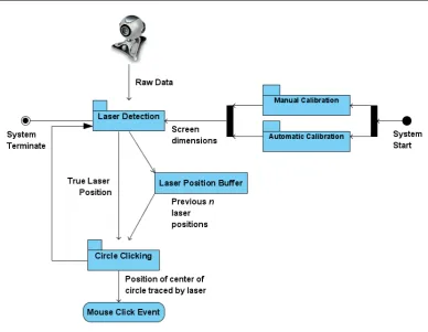
This laser detection system will consist of three main subsystems, and the relationships
between the subsystems is shown in the top level system design diagram shown in
Figure 3.1. The main subsystem will be the laser detection subsystem, which will be
quite complicated in that it deals with the interface to the webcam, the detection of
Figure 3.1: Laser pointer mouse overall system design showing the various subsystems
detection subsystem which will deal with the motion tracking of the laser in order to
detect the presence of a circle being traced and return the coordinates of center of the
circle. The other subsystem is the calibration subsystem which will consist of manual
and automatic calibration.
3.4.1 Calibration Subsystems
The aim is to have automatic calibration, but before this is achieved, manual
calibra-tion will need to be achieved. Therefore it is shown in the system design diagram (
Figure 3.1) as two separate subsystems close together and may both contribute to the
calibration of the laser.
Manual calibration might involve the system having to project a special calibration
image onto the screen that displays four bright dots, one in each corner of the screen
3.4 The overall system architectural approach 29
webcam of this projection and then detects the position of the four dots on the screen
in the form of pixel coordinates that then later gets used to determine the true position
of the laser. This is a manual process that takes some time at the beginning of a session
before the system can be used effectively.
With auto-calibration the system would be able to dynamically detect the position of
the four corners of the screen and then return the pixel coordinates that can be used
in calibration. This could be done before the session like with manual calibration, or it
could be done ”on the fly” during each laser detection, or every predetermined number
of frames being read in. This latter method may result in a drop in response time due
to the additional graphics processing that will be required for this.
Both the manual and automatic calibration methods could be used. The manual
cal-ibration method could be used as a backup if the automatic calcal-ibration doesn’t work.
But for the project, achieving the manual calibration would be more important than
the automatic calibration. The calibration subsystems provide the laser detection
sub-system with the information required to refine the position of the laser by supplying it
with the dimensions of the screen.
3.4.2 Circle Clicking Subsystem
The circle clicking subsystem will be responsible for taking information about last
predefined number of positions of the laser and determining whether a circle has been
traced, and if so, return the coordinates of the center of the circle. These coordinates
is used in conjunction with the Windows API to perform a click event that would click
on the area of the screen where the laser traced a circle.
This subsystem will also detect whether the circle was traced clockwise or anti clockwise.
This information will be used along with the coordinates to perform either a left or
a right click depending on whether the circle was traced anti-clockwise or clockwise
respectively.
As shown in Figure 3.1, there is a laser position buffer in between the laser detection
Figure 3.2: Laser detection subsystem with its three layers
previous laser positions that will be accessed by the circle clicking subsystem.
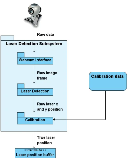
3.4.3 Laser Detection Subsystem
The laser detection subsystem will be a large subsystem consisting of three separate
subsystems as shown in Figure 3.2. The inputs to this subsystem are the pictures taken
by the webcam and the calibration data.
The laser detection starts with the webcam interface, which is a system that has been
developed by ¡reference to john leis system and other references to this system¿. This
system is only concerned with obtaining a frame from the webcam so that its contents
can be analyzed and scanned for the presence and location of the laser.
The frame is then passed onto the laser detection layer which does all of the work to
do with finding the location of the laser in the frame.
3.5 The work breakdown structure 31
which uses the calibration data to produce the correct laser position which then ends up
in the laser position buffer, which is used by the circle clicking subsystem for analysis
and detection of a circular motion.
These three layers, the webcam interface (JL) layer, the laser detection layer, and the
calibration layer makes up the laser detection subsystem.
3.4.4 System components meeting the specifications
The various subsystems in this laser pointer mouse system, once completed, would meet
the specific objectives outlined in Chapter 1. Already the laser detection subsystem
meets the objective for investigating the color point detection, and future work on the
calibration and circle tracking subsystems would meet the rest of the specific objectives
outlined in Chapter 1.
3.5
The work breakdown structure
The work breakdown structure begins with the major components given in the previous
section which is the top level expectation of how this problem will be solved.
In this section the expected work that will need to be performed to fulfill the outcomes
of each component will be briefly explained and will lead to the development of a more
detailed WBS that will be the first stage of planning the time lines for the project. The
explanation of each component is given below starting with its expected outputs and
3.6
Top Level WBS explained in more detail
3.6.1 Setting up and preparation
During this component which will be the first phase of the practical and technical work
for this project, all of the necessary tools and facilities that will be needed to complete
this project needs to be obtained, both hardware and software. The obvious hardw