UNIVERSITI TEKNIKAL MALAYSIA MELAKA
DEVELOPMENT OF BLIND SPOT DETECTION SYSTEM
FOR VEHICLE
This report submitted in accordance with requirement of the Universiti Teknikal Malaysia Melaka (UTeM) for the Bachelor of Electronics Engineering Technology
(Industrial Electronics) with Honours.
by
NOR NATASHA BINTI CHE PA B071310507
930609-02-5728
FACULTY OF ENGINEERING TECHNOLOGY
iii
DECLARATION
I hereby, declared this report entitled development of the blind spot detection for vehicle is the results of my own research except as cited in references.
Signature : ……….
Author’s Name : Nor Natasha Binti Che Pa
iv
APPROVAL
This report is submitted to the Faculty of Engineering Technology of UTeM as a
partial fulfillment of the requirements for the degree of Bachelor in Electronic Engineering Technology (Industrial Electronic) with Honours. The member of the supervisory is as follow:
………
v
ABSTRAK
vi
ABSTRACT
Driving a vehicle in current conditions is highly risky. In fact, if the driver is not aware of the presence of a vehicle or obstacle in his blind spot, a crash can easily occur. The objective of this project is to propose a solution to improve a driver’s
safety when changing lanes on the road, which focuses on the low-end vehicle. The Blind Spot Detection (BSD) system based on wireless detecting technique is proposed to monitor the blind spot area for the presence of obstacles, automobiles or other objects. The BSD systems are mounted on the left side mirror and the right side mirror of the vehicle. The detection of cars in the blind spot region is displayed by warning light indicators. The BSD system algorithm proposed here is based on a distance calculation between the object. The ultrasonic sensor is programmed at certain parameter or distance to detect upcoming vehicle, object or obstacle to activate the warning light indicator circuitry. If the blind spot region of the vehicle can be minimized, it is expected the accident cases could be reduced.
vii
DEDICATION
Special dedication to:
To my mother, father, siblings, housemate, friends and her to always support and
encourage me through my education journey.
My supervisor Miss. Siti Halma Binti Johari
viii
ACKNOWLEDGEMENT
In the name of Allah, the Most Beneficent and Most Merciful.
Firstly of all, all praised to Allah with the Most Kindness for giving me a chance to finish and completed this project.
Besides, I would like to express my greatest gratitude to my respected supervisor Miss. Siti Halma Binti Johari for his guidance, encouragement, invaluable support and motivation through the whole completion of this project. This project would not be succeeded without her continuous support.
Secondly, I would like to drop my sincere appreciation to thank to my family
who have motivated me and support me in completing this project. Thanks for their encouragement, love and emotional supports that they had given to me.
ix
TABLE OF CONTENT
Declaration iii
Approval iv
Abstrak v
Abstract vi
Dedication vii
Acknowledgement viii
Table of Content ix - x
List of Tables xi
List of Figures xii - xiii
List Abbreviations, Symbols and Nomenclatures vix
CHAPTER 1: INTRODUCTION 1
1.0 Introduction 1
1.1 Problem Statement 2-3
1.2 Project Objective 3
1.3 Project Scope 4
1.4 Thesis Outline 4
CHAPTER 2: LITERATURE REVIEW 5
2.0 Introduction 5
2.1 Blind Spot Detection System 5-6
2.1.1 Volvo 6-7
2.1.2 Ford 7
2.1.3 BMW 8
2.2 The Ideas of BSD System from Previous Project 8 2.2.1 Mono-Camera Based Side Vehicle Detection for Blind Spot
Detection System 9-10
2.2.2 Robust Vehicle Detection and Tracking Method for Blind Spot
Detection System Using Vision Sensors 11-13
2.3 Ultrasonic Sensor 14-15
x
2.4 Arduino UNO 16-17
2.5 HC-05 Bluetooth Serial Modules 18-20
2.6 Battery Supply 20
2.7 LED 21
2.8 Buzzer 21-22
2.9 Arduino IDE Software 22-23
CHAPTER 3: METHODOLOGY 24
3.0 Introduction 24
3.1 Project Overview 24-25
3.2 Flowchart of Overall Project Workflow 26
3.3 Hardware Implementation 27
3.3.1 Block Diagram of BSD System 27
3.3.2 Flowchart of BSD System 28
3.3.3 Wireless Ultrasonic Sensor Circuit 29
3.3.4 Warning Light Indicator Circuit 29
3.4 Software Implementation 30
3.4.1 Master Bluetooth Module 31-33
3.4.2 Slave Bluetooth Module 34-36
CHAPTER 4: RESULT 37
4.0 Introduction 37
4.1 Overall Implementation Result 38
4.2 Result of the Project 38-40
4.3 Analysis of the Project 41-44
CHAPTER 5: CONCLUSION & RECOMMENDATION 45
5.0 Conclusion 45
5.1 Recommendation 46
REFERENCES 47-49
xi
LIST OF TABLES
2.1 The HC-SR04 Details 15
2.2 The Arduino UNO Basic Specification 17
2.3 The Parameter of Bluetooth Serial Module 19
2.4 The Piezo Buzzer Basic Specification 22
4.1 The Overall Implementation of the Project 38
4.2 Operation of the Project 40
xii
LIST OF FIGURES
1.1 The Blind Spot Definition 2
1.2 The Blind Spot Information System 3
2.1 The Blind Spot Information System (BLIS) of Volvo 7
2.2 The Blind Spot Information System (BLIS) of Ford 7
2.3 The Blind Spot Information System (BLIS) of BMW (5series) 8
2.4 The Blind Spot Warning Zone 9
2.5 The Blind Spot Warning Zone Flowchart 10
2.6 The Blind Spot Warning Zone Result 10
2.7 The System Equipment by Top View 11
2.8 The System Configuration 12
2.9 The Original Image and Processed Image 12
2.10 The Original and Processed Image with Blind Spot Detection
System Information 13
2.11 The HC-SR04 Ultrasonic Sensor 14
2.12 Basic Concepts of „Ping‟ and „Pong‟ 15
2.13 The Arduino UNO 17
2.14 HC-05 Bluetooth Serial Modules 19
2.15 Battery Supply 9V 20
2.16 LED 21
2.17 Piezo Buzzer 21
2.18 Arduino Software 23
xiii 3.2 Block Diagram of BSD System for Wireless Ultrasonic Sensor Circuit 27
3.3 Block Diagram of BSD System for Warning Light Indicator Circuit 27
3.4 Flowchart of BSD System 28
3.5 Designs for Wireless Ultrasonic Sensor Circuit 29
3.6 Designs for Warning Light Indicator Circuit 29
3.7 Software Flowchart of BSD System 30
3.8 Flowchart of Master Bluetooth Module 31
3.9 Initialize Sensor 32
3.10 Calculation Ultrasonic Sensor 32
3.11 Danger Zone 32
3.12 Alert Zone 33
3.13 Safe Zone 33
3.14 Flowchart of Slave 34
3.15 Bluetooth Receiver Read Data 35
3.16 Condition at State 0 35
3.17 Condition at State 1 35
3.18 Condition at State 2 36
4.1 Blind Spot Detection System 37
4.2 The Connection Bluetooth between Master and Slave 39
4.3 The Graph of Reaction Time to Detect the Object from Near to Far 42
4.4 The Graph of Reaction Time to Detect the Object from Far to Near 44
xiv
LIST OF ABBREVIATIONS, SYMBOLS AND
NOMENCLATURE
UTeM - Universiti Teknikal Malaysia Melaka PSM I - Project Sarjana Muda I
PSM II - Project Sarjana Muda II BSD - Blind Spot Detection
BLIS - The Blind Spot Information System LED - Light Emitter Diode
RIO - Region of Interest LBP - Local Binary Pattern
HoG - Histogram of Oriented Gradient Haar - Haar-Like-Based LP Detectors
1
1.0 Introduction
Driving a vehicle in current situations is exceptionally unsafe on the grounds that most mishaps are identified with driver's carelessness. The high hazard can
happen if the driver looks the street of approaching threat and in the meantime think back on expressways driving. It is imperative to look both sideway and backward before securely changing the lanes. An issue that frequently worried by the driver is the regions can't be seen by side view and rear mirrors, which is known as blind spot region of a vehicle [5]. Thusly, in a few accident cases, it happens because of an inability driver’s to monitor the blind spot region well.
In Figure 1.1 show on the following page, the region called a blind spot is the back quarter blind spot, the region towards the back of the vehicle. Vehicles in the nearby paths of the street may classifications as blind spots and a driver once in a while can't see contiguous vehicle utilizing just the car mirrors. Then, the other area that is once in a while called blind spot is those that shorted to see behind and before a vehicle. Additionally, in situations where side view is blocked, regions to the left or right can get to be blind spot [4].
2
Figure 1.1: The Blind Spot Definition
1.1 Problem Statement
These days, innovation in vehicles has been quickly expanding to lessen the danger of mishap while driving vehicle. A few accident cases happens as a result of a powerlessness driver's to monitor the blind spot region and an issue that frequently worried by the driver is the area can't be seen by side view and back perspective mirrors, which is known as blind spot area as well [5]. There are numerous sorts of exploration proposed in view of the driving help framework concentrating on the blind side locale. The modern technology based on sensors like camera, laser, ultrasonic and radar are most likely applies in high-end and high-tech vehicle to monitor blind spot region.
All of the high-end and high-tech cars are most likely to have embedded system of blind-spot detection and these active blind spot detection systems are not available for low-end vehicle. This blind spot detection system in high-end vehicle is also remade act as driving assistance system for driver and implement into low-end vehicles. However, the high product price and installation cost are the some of the factor which do not attract the low end users to use BLIS system.
3 affordable price for low-end vehicle is an important task to reduce collision among vehicle.
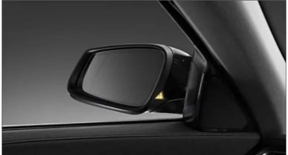
Figure 1.2: The Blind Spot Information System [7]
1.2 Project Objectives
The objectives of this project are:
1. To develop a portable and wirelessly controlled BSD system for low-end
vehicle.
2. To calculate the distance for detecting object when vehicle enter the blind spot region.
4
1.3 Project Scope
They a several scopes of work have been determined are as follows:
The system will utilize ultrasonic technology.
BSD system is appropriate to apply for car, van and a little lorry.
A solution to improve a driver’s safety when changing lanes on the road.
1.4 Thesis Outline
This project involves five chapters. Chapter 1 consists of the overview of the project that describes the project in general like little bit project background, problem statement, project objectives and scope of project. Chapter 2 contains literature review that related with this project where all the information regarding the project shown in this section. The explanation is based on gathered information from the journal, thesis, internet, reference books and relevant article. Chapter 3 contains the methodology that explains the in detail the overall
5
2.0 Introduction
The literature review was clarifies all through the theory project to increase the knowledge and enhance skills to finish this project. The main sources for this project are the research previous thesis that related with my project, books, journals and articles that mostly provided by UTeM and UTeM library. This chapter focuses on the basic concept and fundamental theories which related to this project.
2.1 Blind Spot Detection System
As indicated by the statistics, the majority of car crashes are identified with drivers' disruption. In the event that a driver is alarmed at 0.5 seconds before being an accident, it can stay away from no less than 60% of backside crashes, 30% of head-on accidents and 50% of street slope related traffic accidents. In the event that
cautioned before one second, it can avoid 90% of accidents. The statistics indicated traffic accidents can be lessened if the drivers have enough response time. In this
way, blind spot detection (BSD) system, which is smart vehicle equipment, is created for such needs [1] [2].
Blind spot detection has been produced with a goal to distinguish the nearness of a vehicle or other object in the driver's blind spot. The driver's blind spot
6 is that divide of the vehicle in which an object won't ordinarily be seen by the utilization of the inside and outside mirrors of the vehicle [3]. The BSD system is a safety method for vehicles [2]. All the more particularly, the BSD system utilizes ultrasonic sensor, to distinguish deterrents in blind spot area on a left, right and back sides of a vehicle. If BSD system notices that a particular snag exists in a blind spot area, the BSD system effectively conveys a message of light or sound, for instance, to a driver, so that the driver can decide a driving course appropriately, to stay away from a crash because of the driver's careless or blind spot of vision [2].
Henceforth, around 75% of the mishap during lane changes is because of driver Situation Awareness disappointment [4]. Blind spot monitoring system is importance to enhance visibility and diminish the blind zone in order to execute safety driving [2].
These days, the blind spot monitoring system is applied in some type of
vehicles. The present day innovation based on sensors like camera, laser, ultrasonic and radar are applied in high-end and high-tech vehicle, for example, Volvo, Ford, BMW and Audi [7]. In the interim, low-end vehicle needs driving help of blind spot monitoring system.
2.1.1 Volvo
7
Figure 2.1: The Blind Spot Information System (BLIS) of Volvo [6]
2.1.2 Ford
Ford vehicle additionally actualizes the same BLIS sensor that Volvo developed. As appeared in Figure 2.2, Ford vehicle places radar-based detectors close to the back of the car, however, the light that flashes to caution driver of shrouded vehicle is on the outside back perspective mirror.
Audi vehicle additionally presented Audi Side Assist that will recognize cars coming up from to the extent 150 feet (45.7 meters) behind in abutting paths and blaze a light in an outer back perspective mirror [4].
[image:20.595.217.494.553.714.2]8
2.1.3 BMW
[image:21.595.211.498.323.478.2]BMW (5series) model have the dynamic blind spot discovery to ready driver if there any up and coming potential peril in blind spot zone. From Figure 2.3, dynamic blind spot discovery arrangement of BMW (5series) model disposes of blind spots and really permits drivers to stay away from crashes while switching to another lane, actually keeping your look straight ahead. Utilizing radar detecting to distinguish substance vehicle and put at the back of the vehicle. This system cautions drivers if a vehicle is in their blind spot locale vehicle. The light show on their side-view mirror lodgings starts to streak furthermore guiding wheel vibrates [4].
Figure 2.3: The Blind Spot Information System (BLIS) of BMW (5series) [16]
2.2 The ideas of Blind Spot Detection System from Previous Project
The main reason for development thoughts of BSD system is to understand strategy utilized in previous project of blind spot monitoring system before use to
9
2.2.1 Mono-Camera Based Side Vehicle Detection for Blind Spot Detection Systems [8]
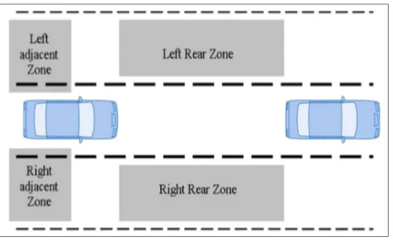
[image:22.595.218.496.341.515.2]In this research paper, the task concentrate as an afterthought vehicle discovery in the blind side region utilizing picture outlines from the cameras which are introduced as an afterthought mirrors. The classifier-based identification system is utilized as a driving help for vehicle. The classifier-based vehicle identification utilizes highlight vectors, for example, Haar, LBP or HoG. In that plan, the classifier figures out if a picture area is a vehicle or a non-vehicle taking into account the component vector. The venture utilizes the classifier-based discovery to recognize a vehicle in the blind side locale. The figure 2.4 beneath, demonstrate the blind side cautioning zone.
Figure 2.4: The blind spot warning zone
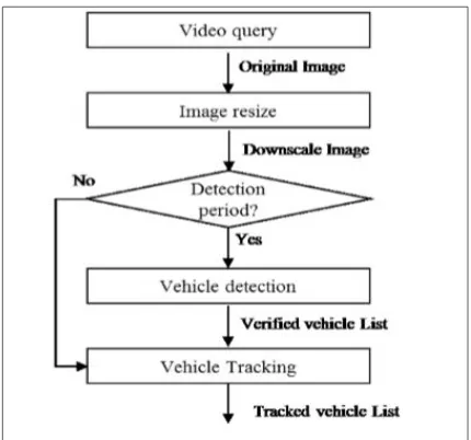
10 performed per a fifth frame, and the detected vehicles are tracked in the four intermediate frames.
Figure 2.5: The Blind Spot Warning Zone Flowchart
[image:23.595.230.483.554.707.2]The region of interest (ROI) has been set where the vehicles can exist with investigations the genuine position of vehicles in the picture outline. The Figure 2.6 beneath demonstrates the area of interest is the red rectangle in the picture. The sky territory has been removed, the neighboring base street surface, and the back zone of the subject vehicle in the picture. The proposed calculation recognizes the vehicle with multi-scale in the locale of interest picture. The course classifier is utilized to distinguish vehicles in the picture.
11
2.2.2 Robust Vehicle Detection and Tracking Method for Blind Spot Detection System by using Vision Sensors [9]
[image:24.595.195.477.324.561.2]In this research paper, the project used the vision sensor method for blind spot detection system. This is because to detect the present of vehicles from side and rear for this system. The vision sensor method using the symmetry and shadows gave a judgment for the target vehicles such as the extracted edge of the object and horizontal line segments, and then the candidates of vehicle were judged. The position of the vehicle was defined with its outer size by using the symmetry of the image histogram.

![Figure 1.2: The Blind Spot Information System [7]](https://thumb-us.123doks.com/thumbv2/123dok_us/136577.13721/16.595.166.521.153.351/figure-the-blind-spot-information-system.webp)
![Figure 2.1: The Blind Spot Information System (BLIS) of Volvo [6]](https://thumb-us.123doks.com/thumbv2/123dok_us/136577.13721/20.595.217.494.553.714/figure-blind-spot-information-blis-volvo.webp)
![Figure 2.7: System Equipment by Top View [9]](https://thumb-us.123doks.com/thumbv2/123dok_us/136577.13721/24.595.195.477.324.561/figure-equipment-view.webp)
