A New Voltage Doubler Based DC-DC 2LC
m
-Y
Power Converter Topologies for
High-Voltage/Low-Current Renewable Energy Applications
Mahajan Sagar Bhaskar
Dept. of Electrical Engg., Qatar University, Doha, Qatar
sagar25.mahajan@gmail.com
Sanjeevikumar Padmanaban
Dept. of Energy Technology, Aalborg University, Denmarksan@et.aau.dk
Patrick Wheeler
Dept. of Electrical & Electronics Engg., Nottingham University, United Kingdom
pat.wheeler@nottingham.ac.uk
Frede Blaabjerg
Center for Reliable Power Electronics (CORPE), Dept. of Energy Technology, Aalborg University, Denmark
fbl@et.aau.dk
Pierluigi Siano
Dept. of Industrial Engg.,University of Salerno, Campus of Fisciano, Salerno, Italy psiano@unisa.it
Abstract— In this treatise, a new voltage doubler based DC-DC 2LCm-Y power converter topologies are uttered for the high-voltage/low-current renewable energy applications. L-Y, 2L-Y, 2LC-Y and 2LCm-Y power converter categories are recently proposed in the existing X-Y converter family. To provide an effective and viable solution to renewable energy system; four new voltage doubler based converters (2LCm-LVD, 2LCm-2LVD, 2LCm-2LCVD and 2LCm-2LCmVD converters) are proposed in 2LCm-Y converter category. The proposed converters are well suited for renewable energy applications which required high output voltage power converter such as a Photovoltaic Multilevel DC-AC converter system, renewable High Voltage Direct Current (HVDC) applications, Hybrid Electric Vehicles (HEV) etc. The perceptible characteristics of proposed 2LCm-Y power converter topologies are presented in detail. Working of 2LCm-Y proposed converters with the derivation of VO/Vin is discussed in detail. Proposed converter topologies are simulated in the Numerical Computing Matrix Laboratory 9.0 (R2016a) software. The simulation results are discussed in details and it constantly showed the high-quality agreement with hypothetical analysis and validates the functionality and characteristics of the proposed 2LCm-Y converter topologies of X-Y converter family.
Keywords— X-Y Converter Family; DC-DC Converter; Voltage Doubler; High-Voltage; Low-Current; Renewable Energy.
I. INTRODUCTION
Presently, looking forward for renewable energy it has become more popular day by day and it can be considered as prominent solution to fulfill energy demand of community. The renewable sources are reliable and plentiful in nature and can be harvested and consequently not defenseless against any sort of dangers. Thus, energy organization concentrates on unlimited of renewable power source assets for power era [1]-[2]. Massive energy era through a course of action of various little voltage producing units is getting mainstream like series and parallel association of solar cell or panels. Consequently, series and parallel association of solar module is not an appropriate way out for accomplish high voltage and high current because of necessity of extensive area and high cost is required. The fine case of such electric power framework is a photovoltaic power plant which contains various photovoltaic oriented boards/modules for generation of energy. Produced
complete output voltage (VO) and that is very high. Thus, high rated capacitors and power controlled devices are required [9].
Nowadays, DC-DC Multilevel Boost Converters (MBC) is addressed in literature to overcome the drawback of above discussed converter using diode and capacitor networks [10]-[14]. In [11], inverted high voltage with conversion ratio 20 and 40 at duty cycle 75% is accomplished using Nx and 2Nx MBC. Reduce current/voltage ripple with high non-inverting voltage is attained by using Nx, 2Nx IMBC [12]-[13]. The multilevel DC-DC converter topology discussed above gives a suitable way to accomplish high voltage however, required substantial number of diode and capacitor. In [14], X-Y converter family is proposed to attain high voltage conversion ratio by utilizing least number of components. In view of the arrangement of inductor, total sixteen converter topologies are proposed in X-Y family. In [15], to achieve high conversion ratio (VO/Vin) novel four L-Y converter topologies using voltage doubler (LVD, 2LVD, 2LCVD and L-2LCmVD) are articulated.
A new voltage doubler based DC-DC 2LCm-Y power converter topologies (2LCm-LVD, 2LCm-2LVD, 2LCm -2LCVD and 2LCm-2LCmVD converters) are proposed in this treatise to provide an effective and viable solution to renewable energy system such as a Photovoltaic Multilevel DC-AC converter system, renewable High Voltage Direct Current (HVDC) applications, Hybrid Electric Vehicles (HEV) etc. The perceptible characteristics of proposed 2LCm -Y power converter topologies are i) Single input source ii) Single controlled semiconductor device iii) High inverting
VO/Vin at average duty cycle iv) High-voltage and low-current at the output side of converter v) Minimum internal resistance vi) Transformer-less and coupled inductor-less power converter topologies. The concept of proposed converter is verified through Numerical Computing Matrix Laboratory 9.0 (R2016a) software.
II. REVIEW OF EXISTING 2LCm-YDC-DCCONVERTERS:A MEMBERS OF X-YCONVERTER FAMILY
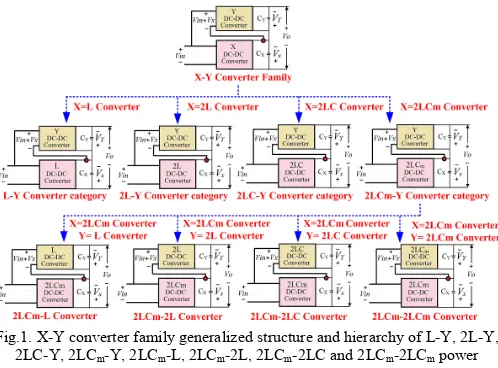
Fig. 1 depicts the X-Y power converter family generalized structure and hierarchy of L-Y, 2L-Y, 2LC-Y, 2LCm-Y, 2LCm -L, 2LCm-2L, 2LCm-2LC and 2LCm-2LCm converters. In X-Y
family two separate DC-DC converters named as X-converter and Y-converter are associated in particular way as depicted in Fig. 1. The contribution for X-converter is directly fed from the input source voltage (Vin) and for Y-converter contribution voltage is addition of input source voltage (Vin) and output of X-converter. The total output voltage of X-Y converter is easily measured by equation (1) in which VX and VY is the output of converter X and Y. GX and GY are the voltage conversion ratio of converter X and Y.
(
)
o X Y
X X in
Y Y in
V
V
V
V
G
V
V
G
V
= −
+
=
×
=
×
(1)
The various combination of Single Inductor (L), Switch-Inductor (SI or 2L), Voltage-Lift-Switched-Switch-Inductor (VLSI or 2LC) and modified-Voltage-Lift-Switched-Inductor (mVLSI or 2LCm) reactive network are employed to designed X-Y converter family. Depending on X converter entire X-Y converter family (sixteen topologies) are categorized into four sub categories; L-Y, 2L-Y, 2LC-Y and 2LCm-Y converter. The entire categorization is shown in Fig. 1. 2LCm-L, 2LCm -2L, 2LCm-2LC and 2LCm-2LCm power converter topologies are existing four member of 2LCm-Y power converter category of X-Y converter family. The power circuits of existing 2LCm-Y converter are shown in Fig. 2(a)-(d). X-converter is 2LCm (modified Voltage-Lift-Switched-Inductor BBC or mVLSI-BBC) in 2LCm-Y power converter category of X-Y converter family. The supply for 2LCm converter is directly fed from the input source voltage (Vin) and for Y converter supply voltage is addition of input source voltage
(Vin) and output voltage of 2LCm converter (X converter,
VX2LCm). As a result, the output voltage of 2LCm-Y power converter is inverting summation of output voltage of 2LCm converter (X converter) and Y converter as shown in equation (2).
(
)
2 - 2
2 - 2
2
-(
)
(
)
o LCm Y X LCm Y
o LCm Y X LCm Y in
o LCm Y X Y in
V
V
V
V
V
V
G
G
V or
V
V
G
G
V
=
= −
+
=
= −
+
×
=
= −
+
×
(2)
III. VOLTAGE DOUBLER BASED 2LCm-YDC-DCCONVERTER TOPOLOGIES (PROPOSED TOPOLOGIES)
[image:2.595.43.292.53.237.2]Four voltage doubler based 2LCm-Y power converter topologies in 2LCm-Y category of X-Y family are proposed to accomplish higher (Vo/Vin) voltage conversion ratio compared to conventional 2LCm-Y converter configurations. Y-converter of conventional 2LCm-Y converter category is modified by employing voltage doubler stage to design proposed converter topologies. Four proposed voltage doubler based power converter topologies are i) 2LCm-LVD power converter (where Y-converter is LVD converter which combines the features of L converter (conventional Buck Boost) and voltage doubler (VD) and X converter is 2LCm converter) ii) 2LCm -2LVD (where Y-converter is -2LVD converter which combines the features of 2L converter (Switched Inductor Buck Boost) and voltage doubler (VD) and X converter is 2LCm converter)
Fig.1. X-Y converter family generalized structure and hierarchy of L-Y, 2L-Y, 2LC-Y, 2LCm-Y, 2LCm-L, 2LCm-2L, 2LCm-2LC and 2LCm-2LCm power
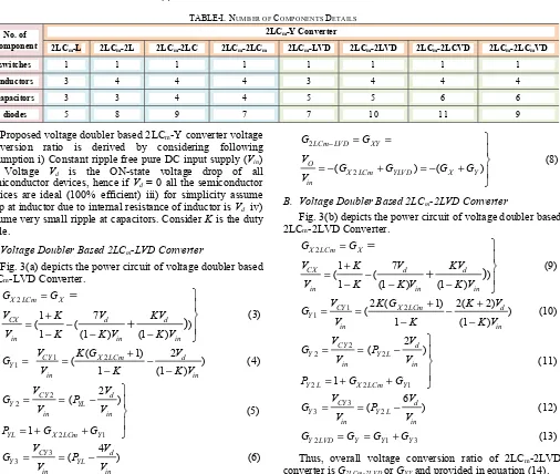
iii) 2LCm-2LCVD (where Y-converter is 2LCVD converter which combines the features of 2LC converter (Voltage Lift Switched Inductor Buck Boost) and voltage doubler (VD) and X converter is 2LCm converter) iv) 2LCm-2LCmVD (where Y- converter is 2LCmVD converter which combines the features of 2LCm converter (modified Voltage Lift Switched Inductor Buck Boost) and voltage doubler (VD) and X converter is 2LCm converter). The main power circuit of proposed four voltage doubler based converters is depicted in Fig. 3(a)-(d). The detail information of requirement of number component to design 2LCm-Y converter is tabulated in table-I. The switching states of all 2LCm-Y converter topologies are divided into two states- one when the control semiconductor device is in ON-state (short circuit) and second when the control semiconductor device is in OFF-state (open circuit). Among the four proposed voltage doubler based converter topologies; 2LCm-2LCmVD is considered to explain the switching states of proposed converters.
A. Voltage Doubler Based 2LCm-2LCmVD Power Converter 2LCm-Y category of X-Y converter family is extended and 2LCm-2LCmVD power converter is one new proposed member in 2LCm-Y category. Modified VLSI BBC converter (2LCm) is considering as an X-converter, whereas Y-converter is combination of 2LCm and voltage doubler (2LCmVD or modified VLSI BBC with voltage doubler). Fig. 3(d) depicts the power circuit of voltage doubler based 2LCm-2LCmVD converter. Two capacitors (C1andCX), two inductors (LX1 and
LX2) which are indistinguishable and equal in rating, four uncontrolled semiconductor devices (diodes DX1 to DX4) are compulsory needed to design 2LCm converter which is X converter of 2LCm-2LCmVD power converter. Four capacitors (C2and CY1 to CY3), two inductors (LY1 and LY2) which are indistinguishable and equal in rating, five uncontrolled semiconductor devices (diodes DY1 to DY5) are compulsory needed to design 2LCmVD converter which is Y-converter of 2LCm-2LCmVD power converter. Therefore, overall to design 2LCm-2LCmVD converter, four indistinguishable inductors which are equal in rating, nine uncontrolled semiconductor device (diodes) and six capacitors besides one semiconductor controlled device (Switch) are compulsory required.
When semiconductor controlled device S is in ON-state (short circuit), the slope of current flowing through inductors
LX1 and LX2 are positive. Hence, LX1 inductor is magnetized by input supply (Vin) by way of uncontrolled devices DX1, DX2 and controlled device S (charging path is Vin-S-DX1-LX1-DX2-Vin) whereas LX2 inductor is magnetized by input supply (Vin) by
way of uncontrolled devices DX1, DX3 and controlled device S (charging path is Vin-S-DX1-DX3-LX2-Vin). By way of uncontrolled devices DX1, DX3, DX2 and controlled device S; capacitor C1 is get charged by input voltage (Vin) (charging path is Vin-S-DX1-DX3-C1-DX2-Vin). The slope of current flowing through LY1 and LY2 inductor is positive at the same time. Hence inductor LY1 and LY2 are magnetized. Thus, LY1 inductor is magnetized by capacitor CX voltage and input supply (Vin) by way of uncontrolled devices DY1 and controlled device S (charging path Vin-S-LY1-DY1-CX-Vin) whereas inductor LY2 are charged by capacitor CX voltage and input supply (Vin) by way of uncontrolled devices DY2 and controlled device S (charging path Vin-S-DY2-LY2-CX-Vin). By way of uncontrolled devices DY1, DY2 and controlled device S; capacitor C2 is get charged by capacitor CX voltage and input voltage (Vin) (charging path is Vin-S-DY2-C1-DY1-CX-Vin). By way of uncontrolled devices DY4 and controlled device S, capacitor CY2 is charged by input voltage (Vin), capacitor CY1 and CX voltage (charging path is Vin-S-CY2-DY4-CY1-CX-Vin). Thus, inverting addition of capacitor CX and CY (CY=CY1+CY3) voltages is output voltage of 2LCm-2LCmVD power converter. Main input supply is isolated from the power circuit of 2LCm converter when semiconductor control device S is in OFF-state (open circuit). The slope of current flowing through inductor LX1, LX2 is negative. Hence LX1, LX2 inductors demagnetized in series with capacitor C1 by way of uncontrolled device DX4 to transfer the stored energy to capacitor CX (charging path is LX1-C1-LX2-CX-DX4). The slope of current flowing through inductor LY1, LY2 is negative. Hence, at the same time LY1, LY2 inductor demagnetized in series with capacitor C2 by way of uncontrolled device DY3 to transfer the stored energy to charge the capacitor CY1 (charging path is LY1-C2-LY2-CY1-DY3). CY2 capacitor transferred its energy to charge CY3 capacitor by way of uncontrolled device
DY5. Thus, inverting addition of capacitor CX and CY (CY=CY1+CY3) voltages is output voltage of 2LCm-2LCmVD power converter. Inductor current slope is analyzed for the 2LCm-2LCmVD power converter and the nature of inductor current is shown in Fig. 4. It is observed that that all the inductors available in proposed 2LCm-2LCmVD converter are magnetized when the semiconductor controlled device is in ON-state and demagnetized when semiconductor controlled device is in OFF-state.
IV. DERIVATION OF VOLTAGE CONVERSION RATIO FOR PROPOSED 2LCm-YCONVERTER
(a) (b) (c) (d)
Proposed voltage doubler based 2LCm-Y converter voltage conversion ratio is derived by considering following assumption i) Constant ripple free pure DC input supply (Vin) ii) Voltage Vd is the ON-state voltage drop of all semiconductor devices, hence if Vd= 0 all the semiconductor devices are ideal (100% efficient) iii) for simplicity assume drop at inductor due to internal resistance of inductor is Vd iv) assume very small ripple at capacitors. Consider K is the duty cycle.
A. Voltage Doubler Based 2LCm-LVD Converter
Fig. 3(a) depicts the power circuit of voltage doubler based 2LCm-LVD Converter.
2
7 1
( ( )
1 (1 ) (1 )
)
X LCm X
CX d d
in in in
G G
V K V KV
V K K V K V
= +
= −
− − −
=
+
(3)
1 2
1
( 1) 2
( )
1 (1 )
CY X LCm d
Y
in in
V K G V
G
V K K V
+
= = −
− − (4)
2 2
2 1
2
( )
1
CY d
Y YL
in in
YL X LCm Y
V V
G P
V V
P G G
= = −
= + +
(5)
3 3
4
( )
CY d
Y YL
in in
V V
G P
V V
= = − (6)
1 3
YLVD Y Y Y
G =G =G +G (7) Thus, overall voltage conversion ratio of 2LCm-LVD converter is G2LCm-LVDor GXYand provided in equation (8).
2
2
( ) ( )
LCm LVD XY
O
X LCm YLVD X Y in
G G
V
G G G G
V
− = =
= − + = − +
(8)
B. Voltage Doubler Based 2LCm-2LVD Converter
Fig. 3(b) depicts the power circuit of voltage doubler based 2LCm-2LVD Converter.
2
7 1
( ( )
1 (1 ) (1 )
)
X LCm X
CX d d
in in in
G G
V K V KV
V K K V K V
= +
= −
− − −
=
+
(9)
1 2
1
2 ( 1) 2( 2)
( )
1 (1 )
CY X LCm d
Y
in in
V K G K V
G
V K K V
+ +
= = −
− − (10)
2
2 2
2 2 1
2
( )
1
CY d
Y Y L
in in
Y L X LCm Y
V V
G P
V V
P G G
= = −
= + +
(11)
3
3 2
6
( )
CY d
Y Y L
in in
V V
G P
V V
= = − (12)
2 1 3
Y LVD Y Y Y
G =G =G +G (13) Thus, overall voltage conversion ratio of 2LCm-2LVD converter is G2LCm-2LVD or GXYand provided in equation (14).
2 2
2 2
( ) ( )
LCm LVD XY
O
X LCm Y LVD X Y in
G G
V
G G G G
V
− = =
= − + = − +
[image:4.595.39.383.61.198.2](14) (a) (b) (c) (d)
Fig.3. Voltage Doubler (VD) based proposed converters power circuit (a) 2LCm-LVD (b) 2LCm-2LVD (c)
[image:4.595.51.557.221.649.2]2LCm-2LCVD (d) 2LCm-2LCmVD.
Fig.4. Waveform of inductor current of 2LCm
-2LCmVD converters
TABLE-I. NUMBER OF COMPONENTS DETAILS
No. of Component
2LCm-Y Converter
2LCm-L 2LCm-2L 2LCm-2LC 2LCm-2LCm 2LCm-LVD 2LCm-2LVD 2LCm-2LCVD 2LCm-2LCmVD
switches 1 1 1 1 1 1 1 1
inductors 3 4 4 4 3 4 4 4
capacitors 3 3 4 4 5 5 6 6
[image:4.595.46.284.480.667.2]C. Voltage Doubler Based 2LCm-2LCVD Converter
Fig. 3(c) depicts the power circuit of voltage doubler based 2LCm-2LCVD Converter.
2
7 1
( ( )
1 (1 ) (1 )
)
X LCm X
CX d d
in in in
G G
V K V KV
V K K V K V
= + = − − − −
=
+
(15) 1 2 1(1 )( 1) ( - 7)
( )
1 (1 )
CY X LCm d
Y
in in
V K G K V
G
V K K V
+ +
= =
−
+
− (16)2
2 2
2 2 1
2
( )
1
CY d
Y Y LC
in in
Y LC X LC Y
V V
G P
V V
P G G
= = − = + +
(17) 3 3 2 6 ( ) CY dY Y LC
in in
V V
G P
V V
= = − (18)
2 1 3
Y LCVD Y Y Y
G =G =G +G (19) Thus, overall voltage conversion ratio of 2LCm-2LCVD converter is G2LCm-2LCVD or GXYand provided in equation (20).
2 2
2 2
( ) ( )
O LCm LCVD XY
in
X LCm Y LCVD X Y
V
G G
V
G G G G
− = = = − + = − +
(20)D. Voltage Doubler Based 2LCm-2LCmVD Converter
Fig. 3(d) depicts the power circuit of voltage doubler based 2LCm-2LCmVD Converter.
2
7 1
( ( )
1 (1 ) (1 )
)
X LCm X
CX d d
in in in
G G
V K V KV
V K K V K V
= + = − − − −
=
+
(21) 1 2 1(1 )( 1) 6
( )
1 (1 )
YC X LCm d
Y
in in
V K G V
G
V K K V
+ +
= = −
− − (22)
2
2 2
2 2 1
2 ( ) 1 CY d Y LCm in in
LCm X LCm Y
V V G V V G G
P
P
= = − + +
=
(23) 3 3 2 5 ( ) CY d Y LCm in in V V GV
P
V= = − (24)
2 1 3
Y LCmVD Y Y Y
G =G =G +G (25) Thus, overall gain of 2LCm-2LCmVD converter is G 2LCm-2LCmVD or GXYand provided in equation (26).
2 2
2 2
( ) ( )
O LCm LCmVD XY
in
X LCm Y LCmVD X Y
V
G G
V
G G G G
− = = = − + = − +
(26)The relation between voltage conversion ratio versus duty for proposed voltage doubler 2LCm-Y converters with considering maximum Vd=1 is shown graphically in Fig. 5. It is investigated that all the slope of voltage conversion plot is very high after 75% duty cycle. Hence quasi linear region to
operate 2LCm-Y converter is 0 to 75% duty cycle. The effect of internal resistance of proposed 2LCm-Y power converter topologies of X-Y family is minimal as compared to 2LC-Y member of X-Y family.
[image:5.595.47.285.90.288.2]V. NUMERICAL COMPUTING MATRIX LABORATORY 9.0 (R2016A)SIMULATION RESULTS AND DISCUSSION The simulation of proposed 2LCm-Y converter is workout in Numerical Computing Matrix Laboratory 9.0 (R2016a) software with the parameters: 10V input voltage, 240W power and 60% duty cycle. The Pulse Modulation technique with 50kHz switching frequency is employed to control the switch. Fig. 6 depicts the Vo (output voltage) and Io (output current) waveform of voltage doubler based 2LCm-LVD converter. It is investigated that the achieve voltage and current is -239.6V and -0.997A respectively. Thus, -24 voltage conversion ratio (VO/Vin) is noticed at 60% duty cycle. Fig. 7(a) depicts the Vo (output voltage) and Io (output current) waveform of voltage doubler based 2LCm-2LVD converter. It is investigated that the achieve voltage and current is -389.4V and -0.63A respectively. Thus, -39 voltage conversion ratio (VO/Vin) is noticed at 60% duty cycle. Fig. 7(b) depicts the Vo (output voltage) and Io (output current) waveform of voltage doubler based 2LCm-2LCVD converter. It is investigated that the achieve voltage and current is -489.3V and -0.48A respectively. Thus, -49 voltage conversion ratio (VO/Vin) is noticed at 60% duty cycle. Fig. 7(c) depicts the Vo (output voltage) and Io (output current) waveform of voltage doubler based 2LCm-2LCmVD converter. It is investigated that the achieve voltage and current is -489.5V and -0.495A respectively. Thus, -49 voltage conversion ratio (VO/Vin) is noticed at 60% duty cycle. From the discussion done up till now, first it is clear that 2LCm-Y converter topologies have high inverting output voltage. Second, it is investigated that the voltage conversion ratio of 2LCm-2LVD converter is greater than voltage conversion ratio of 2LCm-LVD converter (G2LCm-LVD < G2LCm-2LVD). Third, it is investigated that the voltage conversion ratio of converter 2LCm-2LCVD and 2LCm-2LCmVD converters is greater than the voltage conversion ratio of 2LCm-2LVD converter (G2LCm-2LCVD or G2LCm-2LCmVD > G2LCm-2LVD). Fourth it is investigated that the proposed voltage doubler based 2LCm-Y converter topologies have greater voltage conversion ratio compared to existing 2LCm-Y (without doubler) category of X-Y converter family. Fifth, among the four voltage doubler based 2LCm-Y power converters topologies, 2LCm-2LCmVD provides a maximum conversion ratio with minimal internal resistance effect.
VI. CONCLUSION
High-voltage and low-current at the output side of converter v) Minimum internal resistance vi) Transformer-less and coupled inductor-less converter topologies. Numerical software simulation results of proposed converters constantly shows high-quality agreement with hypothetical analysis.
REFERENCES
[1] F. Blaabjerg, Y. Yang, K. Ma, X. Wang, “Power electronics - the key technology for renewable energy system integration,” Conf. Proc., Intl. Conf. on Renewable Energy Research and Applications, IEEE-ICRERA’15, pp. 1618–1626, Palermo (Italy), 22-25 Nov. 2015. [2] D. Vipin, P. Sanjeevikumar P., V. Karthikeyan , S. Rajasekar, F.
Blaabjerg, S. Pierluigi “Recent advances and challenges of fuel cell based power system architectures and control – A review” Renewable and Sustainable Energy Reviews, vol. 73, pp. 10–18, Jun. 2017. [3] M. S. Bhaskar, S. Padmanaban, F. Blaabjerg, “A Multistage DC-DC
Step-Up Self-Balanced and Magnetic Component-Free Converter for Photovoltaic Applications: Hardware Implementation,” Energies, vol. 10, no. 5, pp. 719, May 2017.
[4] P. Sanjeevikumar, G. Grandi, P. W. Wheeler, F. Blaabjerg, and J. Loncarski, “A simple MPPT algorithm for novel PV power generation system by high output voltage DC-DC boost converter,” Conf. Proc., 24th IEEE Intl. Symposium on Industrial Electronics, IEEE-ISIE’15, pp. 214–220, Rio de Janeiro (Brazil), 3–5 Jun. 2015.
[5] M. Forouzesh, Y. P. Siwakoti, S. A. Gorji, F. Blaabjerg, and B. Lehman, “Step-Up DC-DC Converters: A Comprehensive Review of Voltage-Boosting Techniques, Topologies, and Applications,” IEEE Trans. on Power Electronics, vol. 32, no. 12, pp. 9143–9178, Dec. 2017.
[6] S. K. Changchien, T. J. Liang, J. F. Chen, and L. S. Yang, “Step-up DC-DC converter by coupled inductor and voltage-lift technique,” IET Power Electronics, vol. 3, no. 3, pp. 369–378, May 2010.
[7] M.-H. Keum, Y. Choi, S.-K. Han, and J.-I. Kang, “High efficiency voltage-clamped coupled-inductor boost converter,” Conf. Proc., 39th Annual Conf. of the IEEE Industrial Electronics Society, IEEE-IECON’13, pp. 828–833, Vienna (Austria), 10-13 Nov. 2013.
[8] A. I. Bratcu, I. Munteanu, S. Bacha, D. Picault, and B. Raison, “Cascaded DC-DC Converter Photovoltaic Systems: Power Optimization Issues,” IEEE Trans. on Industrial Electronics, vol. 58, no. 2, pp. 403–411, Feb. 2011.
[9] F. L. Tofoli, D. d C. Pereira, W. J. de Paula, and D. d S. O. Júnior, “Survey on non-isolated high-voltage step-up dc-dc topologies based on the boost converter,” IET Power Electronics, vol. 8, no. 10, pp. 2044– 2057, 2015.
[10] J. C. Rosas-Caro, J. C. Mayo-Maldonado, R. S. Cabrera, A. G. Rodriguez, S. C. Eduardo Nacu, R. Castillo-Ibarra “A Family of DC-DC Multiplier Converters”, Advance online publication: 10 Feb. 2011. [11] M. S. Bhaskar, S. Padmanaban, F. Blaabjerg, O. Ojo, S. Seshagiri, and
R. Kulkarni, “Inverting Nx and 2Nx non-isolated multilevel boost converter for renewable energy applications,” Conf. Proc., 4th IET Clean Energy and Technology Conference, IET-CEAT’16, 2016, pp. 1– 8, Kuala Lumpur (Malayisa), 14-15 Nov. 2016.
[12] M. S. Bhaskar, R. M. Kulkarni, S. Padmanaban, P. Siano, and F. Blaabjerg, “Hybrid non-isolated and non inverting Nx interleaved DC-DC multilevel boost converter for renewable energy applications,” Conf. Proc., IEEE 16th Intl. Conf. on Environment and Electrical Engg., IEEE-EEEIC’16, pp. 1–6, Florence (Italy), 7-10 June 2016.
[13] M. S. Bhaskar, P. Sanjeevikumar, F. Blaabjerg, V. Fedák, M. Cernat, and R. M. Kulkarni, “Non isolated and non-invertingCockcroft-Walton multiplier based hybrid 2Nx interleaved boost converterfor renewable energy applications,” Conf. Proc., IEEE Intl. Power Electronics and Motion Control Conference, IEEE-PEMC’16, pp. 146–151, Varna (Bulagria), 25-28 Sept. 2016.
[14] S. B. Mahajan, P. Sanjeevikumar, P. Wheeler, F. Blaabjerg, M. Rivera, and R. Kulkarni, “X-Y converter family: A new breed of buck boost converter for high step-up renewable energy applications,” Conf. Proc., IEEE Intl. Conference on Automatica, IEEE-ICA-ACCA’16, pp. 1–8, Curico (Chile), 19-21 Oct. 2016.
[image:6.595.108.229.53.166.2][15] M. S. Bhaskar, S. Padmanaban, R. Kulkarni, F. Blaabjerg, S. Seshagiri, and A. Hajizadeh, “Novel LY converter topologies for high gain transfer ratio: A new breed of XY family,” Conf. Proc., 4th IET Clean Energy and Technology Conference , IET-CEAT’16, pp. 1–8, Kuala Lumpur (Malayisa), 14-15 Nov. 2016.
Fig.5. Voltage conversion ratio versus duty cycle plot of 2LCm-Y converter Fig.6. Numerical Computing Matrix Laboratory 9.0 (R2016a) Simulation
Result, 2LCm-LVD converter output current and voltage.
(a) (b) (c)
Fig. 7. Numerical Computing Matrix Laboratory 9.0 (R2016a) Simulation Result of proposed 2LCm-Y converter with 10V, 240W, 0.60 duty cycle with 50kHz
switching Frequency (a) 2LCm-2LVD converter output current and voltage (b) 2LCm-2LCVD converter output current and voltage (c) 2LCm-2LCmVD
[image:6.595.63.539.54.305.2]