UNIVERSITI TEKNIKAL MALAYSIA MELAKA
CFD SIMULATION OF FLUID FLOW PARAMETERS IN
JUNCTION OF AN AIRCRAFT HYDRAULIC PIPE SYSTEM
This report submitted in accordance with requirement of the Universiti Teknikal Malaysia Melaka (UTeM) for the Bachelor’s Degree in Technology Automotive
(Department of Mechanical Engineering Technology) (Hons.)
by
MUHAMAD FARID BIN CHE WAN B071310649
940501025629
DECLARATION
I hereby, declared this report entitled CFD simulation of fluid flow parameters in junction of an aircraft hydraulic pipe system
is the results of my own research except as cited in references.
Signature : ………
Author’s Name : MUHAMAD FARID BIN CHE WAN
APPROVAL
This report is submitted to the Faculty of Engineering Technology of UTeM as a partial fulfillment of the requirements of the Bachelor’s Degree in Technology Automotive (Department of Mechanical Engineering Technology) with honours. The member of the supervisory is as follow:
ABSTRAK
ABSTRACT
DEDICATION
This thesis I dedicated to my beloved parents Che Wan Bin Sulaiman and Asma Binti Bahari. It is with immense gratitude that I acknowledge the support to my supervisor, Puan Najiyah
ACKNOWLEDGEMENT
TABLE OF CONTENT
Abstrak i
Abstract ii
Dedication iii
Acknowledgement iv
Table of Content v
List of Tables vii
List of Figures List of Graphs
viii ix
List of Abbreviations x
CHAPTER 1 : INTRODUCTION 1
1.1 Aircraft Hydraulic Pipe System 1 1.2 Operation of Aircraft Hydraulic Pipe System 1 1.3 Problem Statement 2
1.4 Objective 3
1.5 Work Scope 3
CHAPTER 2 : LITERATURE REVIEW 4 2.1 Aircraft Hydraulic Pipe System 4 2.2 Type of Aircraft Hydraulic Pipe System 6 2.3 Type of Fluid in Hydraulic Pipe System 12 2.4 Turbulence flow 15 2.5 k-epsilon (k-ε) model 20
CHAPTER 3 : METHODOLOGY 24
3.2.3 Geometrical Parameters 28 3.3 CFD Analysis and Simulation 28 3.4 Results Comparison 29
CHAPTER 4 : RESULT AND DISCUSSION 4.1 Simulation of designs
4.1.1 T-junction 4.1.2 Y-junction 4.1.3 Arc-junction
4.2 Results Comparison between T-junction, Y-junction and arc junction 4.2.1 Pressure parameter
4.2.1 Velocity parameter
4.3 Comparison Between Type of Hydraulic Pipe System
CHAPTER 5 : CONCLUSION 5.1 Conclusion
5.2 Recommendation
REFERENCES
30 30 30 35 40 45 45 46 47
48 48 49
LIST OF TABLES
TABLE TITLE PAGE
2.1 Advantages and disadvantages of type of fluids in aircraft hydraulic system 14
LIST OF FIGURES
FIGURE TITLE PAGE
2.1 Inlet geometries at different junctions 7 2.2 Passive double-T-shaped micromixer 8 2.3 Inlet configurations used in the parametric study on bubble size 9 2.4 Comparison between sharp-edge tee and rounded-edge tee 10 3.1 Flow chart of methodology 24 3.2 Computational domain of T-junction 26 3.3 Computational domain of Y-Junction 27 3.4 4.1 4.2 4.3 4.4 4.5 4.6 4.7 4.8 4.9 4.10 4.11 4.12 4.13 4.14 4.15 4.16 4.17
Computational domain of arc-junction T-junction part model
Flow trajectories of pressure in T-junction Cut plot contour of pressure in T-junction Flow trajectories of velocity in T-junction Cut plot contour of velocity in T-junction Y-junction part model
Flow trajectories of pressure in Y-junction Cut plot contour of pressure in Y-junction Flow trajectories of velocity in Y-junction Cut plot contour of velocity in Y-junction Arc-junction part model
Flow trajectories of pressure in Arc-junction Cut plot contour of pressure in Arc-junction Flow trajectories of velocity in Arc-junction Cut plot contour of velocity in Arc-junction
Cut plot contour of pressure in T,Y and Arc-junction Cut plot contour of velocity in T,Y and Arc-junction
LIST OF GRAPHS
GRAPH TITLE PAGE
LIST OF ABBREVIATIONS
α - Alpha
BSL - Baseline
CFD - Computational Fluid Dynamics
℃ - Degree Celsius DT - Double T
EDPs - Engine Driven Pumps
H2 - Hydrogen
mm - Millimetre
> - More than
Ω - Omega
% - Percent
psi - Pressure
Re - Renault Number
σ - Stress
ϵ - Strain
τ - Torque
1
CHAPTER 1
INTRODUCTION
1.1 Aircraft Hydraulic Pipe System
Hydraulic system utilizes a type of fluid under pressure to drive any machinery or apply movement on mechanical parts. Based on the description provided, some of them are present on virtually all of the aircraft types. The utilization of hydraulic power might be constrained to the use of wheel brakes as it were in a light or general aviation aircraft. In bigger and more complex aircraft, it might be utilized to give the muscle to work a wide assortment of parts and systems.
Hydraulic oils function as it transmits power, it lubricates moving parts, seals clearance between moving parts and dissipates heat for cooling purposes. Hydraulic systems comprising of reservoir, accumulator, filter, hydraulic pump, directional control valve and pressure control valve.
This review is identified with Pascal's guideline. The transmission of fluid pressure expresses that pressure applied anyplace in a kept incompressible fluid is transmitted similarly every way all through the fluid with the pressure ratio still the same (Bloomfield, 2006). Pascal's Law expresses that the pressures in both chambers are the same which is (p1=p2).
1.2 Operation of Aircraft Hydraulic Pipe System
2
systems are utilized to control the stabilizer trim, landing gear or flight control surfaces directly, hence get rid of with the requirement for a centralized hydraulic system.
Under every wing side in huge aircraft, there are two hydraulic driven pumps (EDPs). The rudders require expansive stream to change areas, so the two EDPs will supply oil at the same time when the aircraft is under maneuver flight. The three pipes connected by a junction which have two inlets to combine the oil and an outlet to export. (X.Li, 2013).
The primary hydraulic flow and pressure supply for the hydraulic users are represented by EDPs. The regular EDP setup is a compensated pressure, variable displacement cylinder pump fit for shifting the volume of liquid conveyed to keep up hydraulic system pressure. The group is comprised of the parts that achieve the pumping task. The chamber barrel, containing the piston shoe subassemblies, is driven by means of a splined drive shaft. The piston shoe subassemblies are compelled by a hold-down plate and use hydrostatically adjusted shoes that keep running on the holder surface. As the barrel turns, the cylinders respond inside their bores, taking in and releasing fluid through a stationary valve plate interfacing with the port top.
The hanger is supported by bearings that permit angular rotation about an axis perpendicular to the cylinder barrel center line. By changing the angle of the hanger, the length of the piston stroke varies, resulting in a change in pump displacement. During operation, pump discharge pressure is regulated by the aid of compensator. The pressure compensator maintains the delivery pressure by regulating the hanger angle and subsequent discharge flow in response to changes in system pressure.
1.3 Problem Statement
3
Under each wing side in large aircraft there are two hydraulic engine driven pumps which are T junction and Y junction. These junctions will lead to computational of pressure losses (C.N Sokmen, 2011). The new arc junction contributes a curved pipe at the junction in order to minimize the pressure losses.
The flow field in intersection is convoluted because of the property of oil stream speed and diverse frequencies of two intersections in aircraft which are T junction and Y junction. The pressure loss and velocity loss were too huge. To eliminate these issues, an arc junction will be composed (N. Shao, 2011). In view of the flow field of arc junction, the eddy or known as whirlpool in the junction corner may be vanished and the velocity drop expected that would be declined contrasted with T and Y junction.
The calculation of pressure loss is the result of fluid flow in a particular pipe which frequently flows from a high pressure location to a lower pressure location. Based on the 3 designs used, arc junction has been expected to be the best design compared to T-junction and Y-junction (S. Wang, 2013). In this project, arc junction will be designed and the behavior of the fluid flow in the pipe will be compared.
1.4 Objectives
Based on the problem statement, the following objectives were drawn:
1) To design a new model of junction for aircraft hydraulic pipe systems.
2) To simulate the fluid flow properties in the junction with computerized simulation. 3) To compare a new design of branch pipe with the existing T-junction and Y-junction
pipe.
1.5 Work Scope
Based on the objective, the following scopes are formed:
1) Designing a new junction in the shape of arc by using SOLIDWORK software. 2) Simulating the new junction using SOLIDWORK software.
4
CHAPTER 2
LITERATURE REVIEW
2.1 Aircraft Hydraulic Pipe System
Hydraulics term was drawn depends on the Greek word for water and initially implied the investigation of the physical behaviour of water at rest and in movement. Today, the significance has been extended to incorporate the physical conduct of all fluids, including hydraulic fluid. Early aircraft had hydraulic brake mechanisms. As aircraft turned out to be more complex, more up to date systems with hydraulic power were produced. Under each wing side in large aircraft there are two hydraulic engine driven pumps which are T junction and Y junction. These junctions will lead to computational of pressure losses (C.N Sokmen, 2011). The new arc junction contributes a curved pipe at the junction in order to minimize the pressure losses.
5
(IV) liquids. Skydrol® LD4 and Skydrol® 500B-4 water driven liquids are Type IV liquids planned to surpass the inflexible particulars of the flying machine makers. They have been in business use since 1978 and have shown remarkable execution. In 1997, Solutia Inc. was shaped from the substance organizations of Monsanto. Solutia proceeds as the world pioneer in flight water driven liquid administration and support. Skydrol® (LD4) and Skydrol® (500B4) hydraulic fluids are Type (IV) fluids formulated to exceed the rigid requirements of the aircraft producers.
Hydraulic systems function to move and incite landing rigging, flaps and brakes. Bigger aircraft utilize these systems likewise on flight controls, spoilers, push reversers and so forth. The motivation to utilize hydraulic is on account of they can transmit a high pressure and force with a little volume of fluid. Hydraulics depends on the law that fluids are incompressible. A hydraulic system is where the fluid under pressure utilized to transmit energy. The change over mechanical energy from hydraulic power is done by hydraulic pump itself. However, an impelling chamber changes over hydraulic energy to mechanical power.
Hydraulic transmission law is a fluid transmission comprising course and stream control. For example, pressure in a liquid, transmission of drive by a pressure driven liquid, Pascal's law, hydraulic activation, water driven press, framework necessities. Fluid sort and properties containing vegetable, mineral, ester-based oils, hydraulic fluid identification running, filtration sources and outcomes of liquid tainting (Pearson Education Limited, 2007). Aircraft applications containing power framework contrast between electrical, pressure driven and pneumatic. Water driven power applications incorporates landing gear, impediment frameworks (push reverser, arrestor snare, wheel brake, controlling, auto-braking, antiskid), flying controls (ailerons, rudder, lift, tail plane, lift increase, lift decrease, trim, manufactured feel) (Pearson Education Limited, 2007).
6 2.2 Type of Aircraft Hydraulic Pipe System
Aircraft hydraulic pipe system consists of 3 pipe designs which are T-junction, Y-junction and arc Y-junction. Based on the 3 designs used, arc Y-junction has been expected to be the best design compared to T-junction and Y-junction. All these types of designs will be discussed below based on previous study.
From the research of (Wand LY et al.,2008), the oil/water two-stage stream inside T junction was numerically reproduced with a 3-D two-liquid model, and the turbulence was depicted using the blend κ - ɛ demonstrate. A few tests of oil/water stream inside a solitary T junction were directed in the research laboratory. The outcomes demonstrate that the isolating execution of T junction relies on the bay volumetric part and stream designs. A sensible understanding is achieved between the numerical simulation and the analyses for both the oil division circulation and the detachment productivity.
According to (P. Margaris et al., 2007), the standard of element detachment with T junction having a level run and a vertical branch is introduced. The investigation of gas– liquid stream frameworks including T junction is imperative for applications to stage partition in gas–liquid transport pipelines, however the multifaceted nature of the multi-dimensional marvel of isolating two-stage stream in T junction needs exceptional displaying. In light of the key mass, force and energy equation, the numerical model empowers the expectation of stage dissemination and pressure loss through the intersection assessing the two-stage stream design and the stream confinement in the tee-branch. The great understanding of the numerical reproduction comes about with test information approves the scientific demonstrating and prompts to the conclusion that the created computational code is an extremely valuable instrument for the stream portrayal of a T junction separator.
7
In the time of increasing speed, an adverse pressure angle develops at the intersection due to the streamlines shape, bringing about stream partition before stream top, which starts at the comers of the tube cross segment. Stream detachment and reattachment lines, dictated by the restricting streamline topology, move separated amid deceleration. Stream shrewd cross-stream vortices show up in both branches, being much more grounded in the 90° branch.
The attributes of the last vortices, in particular their dissemination, twirl proportion, speed dispersion, and in addition the procedure of their introduction to the world toward the start of every cycle are inspected in detail. Divider shear push dispersions show most extreme qualities at the passageway of the 90° branch, taking qualities corresponding to the gulf time subordinate stream rate (D.S. Mathioulakis et al., 2004). At long last, correlations with enduring delta conditions demonstrated that in the insecure case the stream can support much higher antagonistic pressure before isolating.
[image:20.595.115.532.498.729.2]Based on the exploration by (R. Sierens et al., 2003), the injector situated at 40 cm from the delta valve of the motor is made by Vialle and was intended to convey huge volumes of gas. With an electronic circuit, the beginning of infusion and the infusion span can undoubtedly be managed. The infusion pressure is directed by a valve on the H2 stockpiling bottle. The injector is put at various edges to the delta wind current. Figure 2.1 demonstrates the four analyzed inlet geometries at various intersections:
8
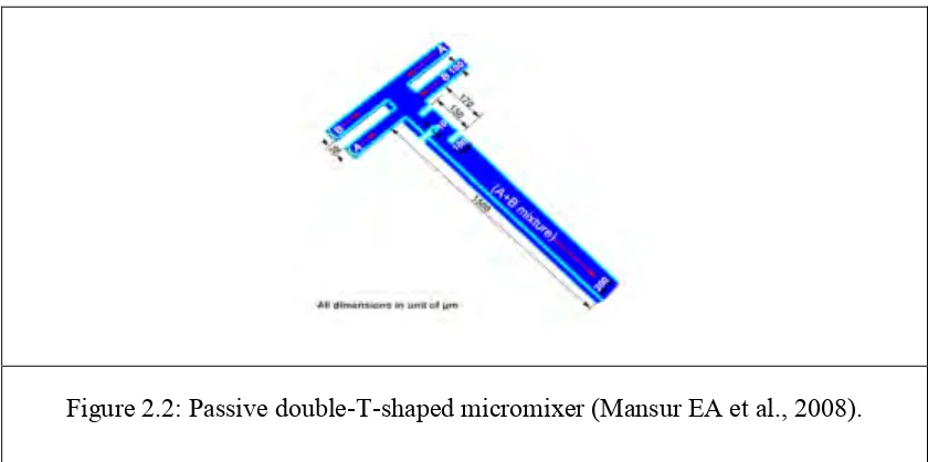
According to (Mansur EA et al., 2008) to additionally comprehend the stream field in the micro mixer, CFD recreations of blending in T micro mixer and DT micro mixer with and without static blending component were completed by utilizing Fluent programming. A 3D strong model of the two blenders was constructed utilizing Gambit, the pre processor for Fluent. The measurements of the two strong models are outlined in Figure 2.2. The strong model of the T micro mixer was comprised of 304000, though the DT micro mixer was comprised of Passive twofold T formed micro mixer with 3 static blending components of 676775 block components. Two species (An) and (B) are thought to be incompressible and their physical properties are indistinguishable to those of water at 20 ℃. Species (A) was
[image:21.595.110.530.308.517.2]indicated to enter the DT micro mixer from the principal right bay and second left gulf while species (B) was determined to enter from the primary left delta and second right bay.
Figure 2.2: Passive double-T-shaped micromixer (Mansur EA et al., 2008).
9
[image:22.595.92.551.205.526.2]In view of the research by (N. Shao et al., 2011), the impact of gulf conditions on the recurrence and size of the air pockets that shape amid gas-fluid Taylor stream in micro channels is reviewed in this paper. Three distinctive gulf designs, T, Y, and M junction and three test channels with water driven breadths 0.345 mm, 0.577 mm, and 0.816 mm were utilized. Figure 2.3 demonstrates the gulf designs utilized as a part of the parametric review on air pocket measure.
Figure 2.3 : Inlet configurations used in the parametric study on bubble size: (a) T-junction (b) Y-junction (c) M-junction. The mixing zones (volumes) at the inlet are shown for the
three configurations. L: liquid inlet, G: gas inlet, O: outlet (N. Shao et al., 2011).
10
From the research of (Costa N.P et al., 2006), the estimations of pressure loss were done for the stream of a Newtonian liquid in 90 deg tee intersections with sharp and round corners. Adjusting the corners decreased the vitality loss by somewhere around 10 and 20%, contingent upon the stream rate proportion, because of the devaluation in the stretching stream drop coefficient, while the straight stream essentially stayed unaffected. The relating point by point estimations of mean and turbulent speeds for a Reynolds number of 31,000 and stream rate proportion of half demonstrated that adjusting the corner prompt to an expansion in turbulence in the branch pipe. The increased turbulence diffused momentum more efficiently thus reducing the length of the recirculation by 25% with its width and strength also decreasing in magnitude.
[image:23.595.111.531.382.582.2]The general impact of the expanded dispersal because of turbulence and diminished dissemination because of mean stream irreversibility in the distribution was a decline in the comparing drop coefficient (Costa N.P et al, 2006). Figure 2.4 shows the comparison between two types of edge.
Figure 2.4 : Comparison between sharp-edge tee(left) and rounded-edge tee(right) (Costa NP et al., 2006).
11 Comparison Between Type of Hydraulic Pipe System
HYDRAULIC PIPE SYSTEM
T-junction Y-junction Others
Insecure stream in a square tube T junction with flat branch, symmetry plane and vertical branch
(Mathioulakis, 2004)
- Stream can keep up much higher
unfavorable pressure angles.
The impact of the infusion parameters with four sorts of junctions (T, Y, 45 deg, 45 deg reverse). (R.Sierens, 2003) -Y junction gains the highest power outlet
Appropriation of three diverse channel
designs (T, Y, M). (N.Shao, 2011) -M junction gets the biggest mixing volume and longer bubbles
PRESENT STUDY: CFD Simulation of Fluid Flow Parameters in Junction Of An Aircraft Hydraulic Pipe System.
- All three drawings which are T-junction, Y-junction and arc junction will be drawn by CATIA (computer aided three-dimensional interactive application) and simulated by using SOLIDWORK software.
- The study will be analyzed from the aspect of diameter of the pipe, fluid velocity and the fluid pressure.
- Based on the 3 designs used, arc junction has been expected to be the best design compared to T-junction and Y-junction.
CFD philosophy used to overcome the issue of the
expectation of the stream in a T junction.
(E.Merzari, 2009)
-An Unsteady Reynolds Averaged Navier-Stokes (URANS) approach has been chosen for its low
computational cost.