Modulated Model Predictive Control with
Optimized Overmodulation
Cristian F. Garcia,
Member
,
IEEE
, Cesar A. Silva,
Member
,
IEEE
, Jose R. Rodriguez,
Fellow Member
,
IEEE
, Pericle Zanchetta,
Senior Member
,
IEEE
, Shafiq A. Odhano,
Member
,
IEEE
.
Abstract—Finite Set Model Predictive Control (FS-MPC) has many advantages, such as a fast dynamic response and an intuitive implementation. For these reasons, it has been thoroughly researched during the last decade. How-ever, the wave form produced by FS-MPC has a switching component whose spread spectrum remains a major dis-advantage of the strategy. This paper discusses a modu-lated model predictive control that guarantees a spectrum switching frequency in the linear modulation range and ex-tends its optimized response to the overmodulation region. Due to the equivalent high gain of the predictive control, and to the limit on the voltage actuation of the power converter, it is expected that the actuation voltage will enter the overmodulation region during large reference changes or in response to load impacts. An optimized overmodula-tion strategy that converges towards FS-MPC’s response for large tracking errors is proposed for this situation. This technique seamlessly combines PWM’s good steady-state switching performance with FS-MPC’s high dynamic response during large transients. The constant switching frequency is achieved by incorporating modulation of the predicted current vectors in the model predictive control of the currents in a similar fashion as conventional Space-Vector Pulse Width Modulation (SV-PWM) is used to syn-thesize an arbitrary voltage reference. Experimental results showing the proposed strategy’s good steady-state switch-ing performance, its FS-MPC-like transient response and the seamless transition between modes of operation are presented for a permanent magnet synchronous machine drive.
Index Terms—Predictive Current Control, Modulated Model Predictive Control.
I. INTRODUCTION
Finite Set Model Predictive Control (FS-MPC) has gained importance thanks to its conceptually simple implementation
Manuscript received October 17, 2017; revised February 9, 2018 and accepted March 30, 2018.
This work was supported in part by Centro Basal FB021 Scientific and Technological Center of Valparaiso (CCTVal) and the Chilean National Fund of Scientific and Technological Development (FONDECYT) under Grants 1170167.
C. Garcia and J. Rodriguez are with the Faculty of Engineer-ing, Universidad Andres Bello, Santiago 8370146, Chile (e-mail: [email protected]; [email protected]).
C. Silva is with the Department of Electronics Engineering, Universi-dad T ´ecnica Federico Santa Mar´ıa, Av. Espa ˜na 1680, Valpara´ıso, Chile (e-mail: [email protected]).
P. Zanchetta and S. Odhano are with the Department of Elec-trical and Electronics Engineering University of Nottingham, Not-tingham, UK NG7 2RD (e-mail: [email protected]; [email protected]).
and very high transient performance. The basic principle of operation is the prediction of the future evolution of the system variables using a dynamic system model in order to select the actuation that optimizes this response. FS-MPC has been implemented successfully in multiple power converter topologies such as neutral point clamped converters (NPC) [1], [2], cascade H-bridge converters (CHB) [3], [4], flying capacitor converters [5], [6], three-phase two-level inverters [7], [8], multilevel converters [3], [9], and matrix converters [10], [11], among others.
However, FS-MPC has two important drawbacks. Firstly, the control strategy depends on the accuracy of the system model, which are not guaranteed due to parametric errors and the presence of unmeasured disturbances. Secondly, the discrete nature of the power converters imposes a very limited number of switching states for the FS-MPC strategy to apply, leading to steady-state error and a spread switching harmonic spectrum.
ac-tuation is saturated. A slightly different approach is presented in [15]. Here, the error between the measured currents and the current references is used to calculate the times of the three vectors, two active vectors and the zero vector, that will result in zero tracking error. The main difference with the previously mentioned methods lies in that, in this method, the tracking error between the reference and the predicted model response is interpreted as an affine transformation, i.e. the combination of a linear transformation and a translation. This leads to an irregular and shifted current response hexagon. The triangular sub-region within the current error hexagon where the origin is located, i.e. the zero error point, can be determinated a priori using vector mathematical properties in the transformed space. This reduces the computational effort and, for linear models, leads to the optimal results without an explicit cost function optimization. Furthermore, the method will lead to good results even for nonlinear systems provided that the state space model is differentiable and that the sampling time is small enough. Again, in the method proposed in [15], no optimization is attempted in the saturation region. All these works have two factors in common: the modulation of the actuation voltage and a dynamic response that achieves dead-beat performance in the linear zone, i.e. within the linear voltage actuation capability of the converter. Nevertheless, none of them present an optimized solution when the refer-ence actuation lies outside of the linear modulation region. Operation in the overmodulation region is relevant when a high dynamics response is necessary, for example in servo applications. In this context, there are other works that propose switching to a different control strategy for the overmodulation region [16]–[19], which adds complexity.
The present work proposes a modulated model predictive control technique with optimized response, including in the overmodulation region. The optimized response in the linear modulation region is solved based on the method presented in [15]. The optimized modulated actuation is found with a system of equations in which the error between the reference and model prediction is modulated to zero. In the overmod-ulation region, the modulated combination of the two active vectors that result in the fastest dynamic response is found. Furthermore, it will be proved that when the reference tracking error is too large, the optimized solution is achieved with a single voltage vector, smoothly converging to the FS-MPC solution, which is known to be optimal for large transient errors. A geometrical criterion that minimizes the current error between the reference and the achievable current vectors, located in the limit of the irregular predicted current error hexagon, is proposed. This criterion is similar to the one proposed in [20] but is applied to the current error, i.e. in the transformed space of the predicted current errors proposed in [15], optimizing the system response rather than the actuation voltage. The proposed technique is experimentally tested as the internal current loop of a permanent magnet synchronous machine drive, showing PWM-like switching performance in steady state, FS-MPC-like transient performance and a smooth transition between both operation conditions.
II. ELECTRICALSYSTEMMODEL
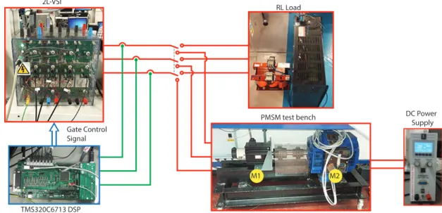
The modulated MPC strategy with optimized overmodu-lation is validated in an experimental setup with two types of load: a passive RL load and a permanent magnetic syn-chronous machine (PMSM). These loads are fed by a two-level voltage source inverter (2L-VSI). In this section, the mathematical models of the inverter and the different loads are presented. Furthermore, these models are discretized in order to implement the strategy in a digital control platform.
A. The Two Level Voltage Source Inverter
Using the spatial vector definition [21], it can be simply shown that the 2L-VSI generates eight voltage vectors, six of which are active vectors while two are zero vectors. The voltage vectors of the power converter, in a stationary αβ -frame, can be expressed as,
vsαβ=vdc· 2 3
h
1 ej23π ej 4π
3
i
·S, (1)
where vdc is the dc-link voltage, S = [Sa Sb Sc]T is the switching state vector of the converter and Sx∈ {0,1}is the switching state of phase x∈ {a, b, c}. This converter voltage can be expressed in a synchronousdq-frame oriented with the angle θby,
vs=vsαβ·e
−jθ. (2)
B. Passive RL Load
The following is the model of the passiveRLload,
Ldis
dt =vs−R·is, (3)
where is is the load current vector, vs is the output voltage vector, R is the resistance value of the load and L is the inductance of the load.
A discrete model is necessary to model the continuous-time system in a digital device control platform. The RL load model is discretized with the forward-Euler approximation by,
dis
dt ≈
ik+1 s −iks
Ts , (4)
whereTs is the sampling period.
C. Permanent Magnet Synchronous Machine
The model of the PMSM in a synchronous dq-frame ori-ented with the rotor position angleθr is as follows,
x= [isd isq ωr θr]T,
u= [vsd vsq]T.
˙
x=f(x,u), (5)
Predictive Model Vector Times Calculation Modulation Stage FS-MPC
Current Control Load
{
Measurements
Fig. 1. Scheme of modulated model predictive control with optimized overmodulation.
where,
f(·) =
−Rs
Lsisd+ωrisq+
1 Lsvsd
−ωrisd−Rs
Lsisq− ψm
Lsωr+
1 Lsvsq
3 2Jmψmp
2isq− Bm
p·Jmωr−TL
ωr , (7)
and the measurement matrix is C= [1 1 0 1].
The parameters of the machine are stator resistance Rs, stator inductance Ls, the magnitude of the flux linkage due to the rotor magnet ψm, the number of pole pairs p, the rotor inertia Jm, the rotor friction coefficient Bm and the rotor angular velocityωr. The load torqueTL is considered a disturbance in this model.
The PMSM model is discretized using a second-order Taylor method as presented in (8).
xk+1=xk+Ts·x˙ k+
T2
s 2 ·x¨
k, (8)
where the second derivative of the state vector is obtained as,
¨
x= ˙f(x,u). (9)
III. CONTROLSTRATEGY
The proposed strategy uses the Finite Set Model Predictive Control (FS-MPC) principle to produce a modulation of the predicted currents in order to follow the reference in minimal time at the same time that it minimizes the switching ripple. This predicted current modulation also includes optimization in the overmodulation zone. The block scheme of the proposed control strategy is shown in Fig. 1. In this section, the stages of the control method are explained in detail.
First, the system’s response is predicted for each of the voltage vectors in the finite set of vectors produced by the power converter, assuming application of each vector for a complete sampling period T s. The current error produced is evaluated by the quadratic cost function (10), in which the objective is a current reference in dq-frame. The active vector that minimizes the error (vopt) and the active vector that produces the second smallest error (v0
opt) are identified. It must be noted that voptandv0
opt are always adjacent vectors.
g(vs,i) =Ed2(vs,i) +Eq2(vs,i), (10)
with,
Ed(vs,i) =i∗d−i
p
d(vs,i), (11)
Eq(vs,i) =i∗q−ipq(vs,i), (12)
where i∗
d and i∗q are the direct and quadrature current ref-erences, respectively. vs,i is the voltage vector of the 2L-VSI, with i∈ {0, . . . ,7}. ipd(vs,i)andipq(vs,i) are the direct and quadrature current predictions based on the load model, respectively. FS-MPC selects the two active voltage vectors of the 2L-VSI that minimize the cost function (10). On the other hand, in the proposed strategy both voltage vectors are modulated with one of the zero vectors in order to reach the current reference in one sampling periodTs. In this way, the cost function is only used to identify the three future voltage vectors that need to be combined in the modulation to average zero predicted current error. These are then modulated to synthesize the optimized actuation voltage. The two identified optimum active vectors are the output of the FS-MPC stage and the input to the modulation stage.
IV. MODULATEDMODELPREDICTIVECONTROL
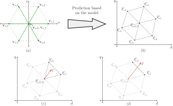
The 2L-VSI has seven actuation voltage vectors (as shown in Fig. 2(a)), which when applied to the load model produce seven different predicted current vectors. As the load model is linear with a back-EMF (in the case of a machine), the transformation between voltage vectors, which are constant in αβ, is an affine transformation, i.e. a linear transformation plus a translation, both of which are time dependent. Hence, the resulting current space vectors also form a hexagon, as the original voltage vectors, but these current space vector’s hexagon is not centered at the origin of the complex plane and is time varying (Fig. 2(b)). The current referencei∗ can lie within the predicted current hexagon. i.e. operating in the linear modulation zone, as depicted in Fig. 2(c), or outside of it, i.e. operating in the overmodulation zone, as shown in Fig. 2(d).
A. Linear Modulation Zone
If the current reference lies in the linear modulation zone, then it is inside the triangle defined byvopt,v0
optandv0. In this
case, by modulating between these three voltage vectors, the current error can be made to average zero in a single sampling period. The problem is then reduced to obtaining the three timesτj withj∈ {0,1,2} that solve the following system of equations, P2
j=0 τj·Ed,j= 0,
P2
j=0 τj·Eq,j = 0,
P2
j=0 τj=Ts,
(13)
where Ed,j and Eq,j are the errors in the d and q axis, produced by the zero vector (v0), the optimum vector (vopt)
and the second optimum vector (v0
opt), as obtained with the cost function (10).
α β
Fig. 2. Geometrical modulation analysis. (a) Voltage vectors of power converter; (b) Load current predictions Hexagon; (c) Linear Modulation zone; (d) overmodulation zone.
than Ts, the current reference is out of the linear modulation zone. Then, the converter cannot reach the current reference in a single sampling period and must enter overmodulation.
B. Overmodulation with Two Active Vectors
When the current reference is located outside the predicted current hexagon, as shown in Fig. 2(c), the converter must be overmodulated. In this condition, the system of equations (13) is no longer applicable. This means that the current cannot reach the current reference in one sampling period due to limitations in the actuation voltage. In this case, the proposed overmodulation optimization finds the converter voltage that minimizes the error between the converter current and its reference subject to the limitations on the voltage actuation.
Solving the modulation problem in the predicted current space, as opposed to in the voltage space, allows for a simple minimization of the current error using a geometrical criterion. In fact, the minimum current error magnitude is the radius of the circumference centered in the reference that just touches the predicted current hexagon, while the resulting optimal current is given by the touch point, as shown in Fig. 3. When this circumference touches one side of the current hexagon, it does so tangentially, and the point can be found by the orthogonal projection of the current reference on the straight line defined by the two optimal current vectors, associated to
voptandv0
opt.
To find the optimized current error, the triangle formed by the current predictions and the current reference, depicted in Fig. 3(a), is considered. The angles α andβ of this triangle can be obtained with the following relationships,
α= arccos
x 1·x3 kx1kkx3k
, (14)
β= arccos
x2· −x3 kx2kkx3k
, (15)
where,
x1=i∗−ips,1, (16)
x2=i∗−ips,2, (17)
x3=ips,1−i p
s,2, (18)
which are calculated according to the sector where the current reference is located, as indicated in Fig. 3(a) and (b). If the current reference is located in zone (1), i.e. the anglesαand β take values between]0, π/2[, then,
τ1=Ts
kx2kcos(β) kx3k
, (19)
τ2=Ts
kx
1kcos(α) kx3k
, (20)
τ0= 0. (21)
The most relevant case for overmodulation with two active vectors is when the modulator is not deeply saturated, i.e. atleast one of the angles α or β is small. In this condition, the equations (19) and (20) can be approximated by (22) and (23), reducing the computational load of the calculation ofτ1
andτ2, respectively.
τ1≈Ts
α
α+β
, (22)
τ2≈Ts
β
α+β
Fig. 3. Geometrical analysis of overmodulation zone. (a) Overmodula-tion with two active vectors; (b) OvermodulaOvermodula-tion with one active vector.
C. Overmodulation by Only One Active Vector
If either α or β, calculated with the equations (14)-(15), respectively, is more than π/2, then the current reference is located in zone (2) of Fig. 3(b). In this case, the overmodu-lation strategy uses only one active vector with the following condition,
τ1=Ts, τ2=τ0= 0 ifα > π/2
τ2=Ts, τ1=τ0= 0 ifβ > π/2
(24)
It must be noted that the larger the current error, the higher the probability of the reference falling in zone (2), where only one voltage vector is applied for the complete sampling period. In this way, the operation smoothly transitions from PWM modulation at small current errors, to two-vector over-modulation in zone (1) and then to FS-MPC performance in zone (2). This ensures optimum performance in every mode of operation.
D. Flow Diagram
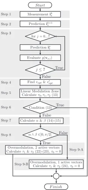
The proposed control strategy can be described by the flow diagram presented in Fig. 4. The steps are described below:
Fig. 4. Flow diagram of the proposed modulated model predictive control with optimized overmodulation.
• Step 1, measurement of the load currentiks. • Step 2, prediction of the current fork+ 1.
• Step 3, prediction of the current for the instant k+ 2 and evaluation of the cost function (10) for all possible vectors of the power converter.
• Step 4, identification of the two active voltage vectors that produces the lowest and second lowest values of the cost function evaluated in the previous step.
• Step 5, calculation of the duty times for the two active vectors found in the previous step and the zero vector, according to equation (13).
• Step 6, evaluation of the validity of the solution of equation (13), according to the subsection IV.A. If it is a valid solution, the flow diagram finishes, and the duty times that will be applied are those calculated in step 5. If the solution is invalid, the flow diagram continues to the following step.
(14)-(15).
• Step 8, evaluation of the angles. If both angles are within ]0, π/2[, the system continues with the step 9-A; if the condition is false, it continues with the step 9-B. • Step 9-A, this condition corresponds to the
overmodula-tion with two active vectors. The duty times are calculated according to the equations (22)-(23).
• Step 9-B, this condition corresponds to the overmodula-tion with one active vector. The duty times are calculated according to equation (24).
V. VERIFICATION OF THEPROPOSEDMETHOD
A. Comparison With FS-MPC and PI-SVM
A verification of the proposed method is presented in this section by comparing it with the standard Finite-Set Model Predictive Control (FS-MPC) and a linear control, in this case proportinonal controller (PI) in synchronous dq−frame with space-vector modulation (PI-SVM). To make a fair comparison, the criteria presented in [22] were used. The proposed method used a PWM with an actualization of the duty cycles every 50[µs]; this means that on average it applies 3 vectors per period. For this reason, the FS-MPC method has been implemented with a sample time of 17 [µs]. The PI-SVM scheme is the same as that used in [22], and the linear controller is a classical PI controller tuned with the Magnitude Optimum (MO) criterion [23]. For the purpose of this comparison, a simple RL load has been chosen. The parameters of the load are presented in the Table I.
Fig. 5 shows the dynamic behavior of the three methods when the quadrature current reference changes from 5 [A] to 10 [A]. The dq-current tracking reference is shown in Fig. 5(a); all the methods have a fast dynamics response. The times it took each method to reach 90 % of the reference were: 406 µs for the MMPC with optimized overmodulation, 374 µs for FS-MPC, and 500 µs for the PI-SVM. Both predictive methods are faster than the PI-SVM; meanwhile the FS-MPC is slightly faster than the proposed method. Initially, both predictive methods take a saturated actuation with only one active vector, which is the constant operational mode of FS-MPC. The small difference is in the overmodulation mode where the proposed method applies two active vectors to optimize thedq−current vector error. Under similar conditions FS-MPC results in a bigger vector error at the end of the sampling period, overshoot the reference. However, for the same reason, the current reaches the reference slightly earlier. The phase currents are presented in the Fig. 5(b), where all the methods have a good sinusoidal wave-form. Fig. 5(c) shows the duty cycles calculated for all the methods. FS-MPC applies one vector per period, so its duty cycles are 0 or 1. The proposed method and PI-SVM have a similar behavior in steady-state, which is regarded as a very good quality of the proposed method. In dynamic state, the MMPC with optimized overmodulation reaches a saturated actuation, similar to FS-MPC, that allows it to obtain a fast response; then it has a soft transition to SVM mode in steady-state.
Fig. 6 presents the output current spectrum for all the methods in steady-state when operating with a reference of 10
[A]. As expected in techniques that use PWM, the proposed method and PI-SVM have a spectrum concentrated around fsw and2fsw and higher multiples offsw (not shown), while the standard FS-MPC has a distributed spectrum, which is typical of this method. The total harmonic distortion values for the three methods are: 1.13 % for the MMPC with optimized Overmodulation, 1.85 % for FS-MPC and 1.22 % for PI-SVM.
B. Sensitivity Analysis
The proposed method is analyzed in the presence of param-eter variations. The electric load paramparam-eters are varied within
±50% of their nominal values (Table I). The total harmonic distortion (THD) and the magnitude of the total steady-state vector error are considered as performance indexes. For simplicity, only one parameter is variated at a time.
Fig. 7(a) shows the results of the resistance variation. The THD has an almost linear variation from 0.97 % to 1.33 %, while the total steady-state error grows quasi-symmetrically as the resistance deviation increases. Fig. 7(b) shows the effect of the inductance variation. The THD has relatively high values for under-estimated inductance values, with a THD of 15.15 % when the inductance is 50 % of the nominal value. For the over-estimation of inductance values, the performance indexes do not present significant increases. In general, the resistance variations have a larger effect in the error, while the inductance under-estimation increases the THD.
TABLE I PARAMETERS
Parameter Value Unit
R 5.7 [Ω]
L 4.06 [mH]
Rs 0.369 [Ω]
Ls 2.4 [mH]
ψm 0.129 [W b]
Jm 1.916·10−3 [Kg·m2]
Bm 4.64·10−3 [N m·rads ]
p 5
VI. EXPERIMENTALRESULTS
The proposed modulated model predictive control with optimized overmodulation was tested experimentally with two different types of loads.
0 5 10 15
-10 0 10
0 0.5 1
0 0.005 0.01 0.015 0.02 0.025 0.03 0.035 0.04 0
5 10 15
-10 0 10
0 0.5 1
0 0.005 0.01 0.015 0.02 0.025 0.03 0.035 0.04 0
5 10 15
-10 0 10
0 0.5 1
0 0.005 0.01 0.015 0.02 0.025 0.03 0.035 0.04
PI-SVM FS-MPC
MMPC with Overmodulation
Fig. 5. Simulation performance comparison of Modulated Model Predictive Control (MMPC) with optimized overmodulation, standard Finite-Set Model Predictive Control (FS-MPC) and PI controller indq−frame with Space Vector Modulation (PI-SVM). (a)dq-current control; (b) Phase currents; (c) Duty cycles.
Fig. 6. Phase output current spectrum of (a) Modulated Model Predictive Control (MMPC) with overmodulation optimization, (b) Standard FS-MPC, and (c) PI-SVM.
time of Ts = 50[µs] is used for the implementation of the control strategy. The PWM frequency of fsw = 10[kHz] is achieved by using symmetrical PWM pulses. The sampling frequency for the proposed method is the same as that used for the asymmetric PI-SVM modulation, i.e. double the carrier frequency of 10kHz, resulting in a sampling frequency of 20 kHz. This is substantially lower than the sampling frequency required by FS-MPC, due to the higher volt-second resolution obtained with PWM respect to that obtained by applying a constant voltage during a whole sampling period. In this sense,
THDisa
T
HD
i
s
a
[%
]
E
rr
or
[%
]
Error
THDisa
T
HD
i
s
a
[%
]
E
rr
or
[%
]
Error
Fig. 7. Sensitivity analysis of the proposed method. (a) Resistance variation; (b) Inductance variation.
the computation effort of the proposed method is significantly lower than that of FS-MPC and only slightly higher than that of the PI control with SV-PWM modulation. The parameters of the RL load and PMSM are presented in Table I.
A. RL Load
RL Load
PMSM test bench
TMS320C6713 DSP Gate Control Signal 2L-VSI
M1 M2
DC Power Supply
Fig. 8. Experimental setup.
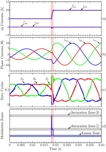
good steady-state performance and a fast dynamic response when the reference changes. In fact, section IV-B shows that the time taken to reach the new current reference is indeed minimal. The phase currents are shown in Fig. 9(b); these currents have a sinusoidal waveform without a perceptible harmonic distortion. The duty cycle of the three phases of the power converter is presented in Fig. 9(c). These waveforms include the typical common mode of space vector voltage modulation, indicating that the utilization of the DC-link is also maximized in the proposed strategy. Also, the duty cycle’s waveforms show some distortion in the zero crossing of the currents. This distortion compensates, via current feedback, for the volt-seconds lost due to dead-time and device voltage drop, effectively cancelling their effects in the currents, as can be appreciated in Fig. 9(b). A signal that represents the location of the current reference in terms of linear or saturated zone of operation is shown in Fig. 9(d). Observing Fig. 9(c), it is also possible to identify when the modulation strategy is operating in the linear modulation zone or in either of the two overmodulation zones: when only one active vector is applied by saturation of the three duty cycles (or overmodulation in zone 2) and when two active vectors are used by saturation of two duty cycles (overmodulation in zone 1). When overmodulation starts, all the duty cycles of all three phases have a binary value (da= 0, db= 1, dc= 1), and then, phase b takes a variable duty cycle, producing a modulation between the switching state [0 1 1]T and the state [0 0 1]T. This result clearly demonstrates the FS-MPC-like performance in response to large errors, the PWM operation in steady state and the smooth transition between modes.
B. PMSM Load
The steady-state behavior of the modulated model predictive control applied to a PMSM is presented in Fig. 10. In this set-up, the shaft of this machine is directly attached to the shaft of a loading DC machine whose speed is kept relatively constant by means of a constant armature voltage. The dq
currents and their references are shown in Fig. 10(a); the quadrature current has good control with neither an observable steady-state error and nor significant ripple. On the other hand, an observable steady-state error is present in the direct current control. This steady-state error may be due to modeling errors in the predictive model which may be parametrical errors in the machine model such as in the magnitude of the back-EMF or un-modeled effects such as nonlinearities of the converter produced by a device voltage drop or dead-time. Model predictive control is always sensitive to model inaccuracies, but this problem is more evident in the modulated model predictive strategy than in FS-MPC due to the lower switching noise. Fig. 10(b) shows the oscilloscope capture of the phase currents, which have a sinusoidal wave-form with the characteristic switching ripple of PWM. The total harmonic distortion (THD) is 3.34 %. The THD for differenti∗
q current reference levels are presented in Table II; the THD’s are lower than 4.5 % in all cases. The current spectrum of the phase current of Fig. 10(b) is presented in Fig. 11. The spectrum has switching harmonics that are concentrated around the fixed carrier frequency and its multiples, as is characteristic of currents produced by PWM modulation.
TABLE II
TOTAL HARMONIC DISTORTION OF THEPMSMPHASE CURRENT.
Current reference [A] THD [%]
6 2.87
8 3.3
10 3.34
12 4.12
0.005 0.01 0.015 0.02 0.025 0.03 0.035 0.04 −10
0 10
0 0.5 1 −5 0 5 10 15
(a)
(b)
(c)
(d)
0
Saturation Zone
Saturation Zone
Linear Zone
−5 5
Modulation Zones
Duty Cycles
Phase Currents [
A
]
Currents [A]
Time [s]
Fig. 9. RL load dynamic responses. (a) Current control indq−frame; (b) Phase currents; (c) Phase duty cycles; (d) Modulation zones.
the loading machine. The phase currents in Fig. 12(b) are sinusoidal without any significant harmonic distortion and show an extremely fast dynamic response.
VII. CONCLUSIONS
A modulated model predictive control with optimized over-modulation has been proposed in this work. In steady state, the constant switching frequency achieved with this technique is an important advantage because it solves the problem of distributed harmonic content in FS-MPC. The modulated voltage actuation of the power converter improves the tracking of the current references and achieves the desired concen-trated PWM switching harmonics. On the other hand, the overmodulation optimization introduced in this work improves the performance of the method during large demand changes, achieving minimum time transients. With this optimization, the inherent voltage error generated when the equivalent reference is located outside of the actuation capability of the inverter is such that the resulting current error is minimized using a sim-ple geometrical consideration. This optimized overmodulation guarantees the fastest dynamic response possible, achieving the same transient performance as FS-MPC for large tran-sients. Furthermore, the use of overmodulation with two active
0 0.01 0.02 0.03 0.04 0.05
−5 0 5 10 15
(a)
(b) Time [s]
Currents [A]
Phase Currents [
A
]
Fig. 10. Steady-state behavior of the PMSM. (a) Current control in
dq−frame; (b) Phase currents.
0 0.5 1 1.5 2 2.5
x 104 0
0.02 0.04
Fig. 11. Phase output current spectrum with PMSM load.
vectors guaranties a smooth settling from overmodulation into the linear modulation zone, achieving a seamless transition.
The experimental results presented confirm the optimal transient response and good steady-state switching spectrum of the proposed modulated model predictive current control with optimized overmodulation.
REFERENCES
[1] J. Scoltock, T. Geyer, and U. K. Madawala, “Model predictive direct
power control for grid-connected npc converters,”IEEE Transactions on
Industrial Electronics, vol. 62, DOI 10.1109/TIE.2015.2410259, no. 9,
pp. 5319–5328, Sep. 2015.
[2] T. Laczynski and A. Mertens, “Predictive stator current control for
medium voltage drives with lc filters,” IEEE Transactions on Power
Electronics, vol. 24, DOI 10.1109/TPEL.2009.2029336, no. 11, pp.
2427–2435, Nov. 2009.
[3] Y. Zhang, X. Wu, X. Yuan, Y. Wang, and P. Dai, “Fast model predictive control for multilevel cascaded h-bridge statcom with polynomial
com-putation time,”IEEE Transactions on Industrial Electronics, vol. 63,
DOI 10.1109/TIE.2016.2572662, no. 8, pp. 5231–5243, Aug. 2016. [4] P. Cortes, A. Wilson, S. Kouro, J. Rodriguez, and H. Abu-Rub,
“Model predictive control of multilevel cascaded h-bridge
invert-ers,” IEEE Transactions on Industrial Electronics, vol. 57, DOI
10.1109/TIE.2010.2041733, no. 8, pp. 2691–2699, Aug. 2010. [5] M. Tomlinson, H. d. T. Mouton, R. Kennel, and P. Stolze, “A fixed
switching frequency scheme for finite-control-set model predictive
con-trol concept and algorithm,”IEEE Transactions on Industrial
Electron-ics, vol. 63, DOI 10.1109/TIE.2016.2593997, no. 12, pp. 7662–7670,
0 0.01 0.02 0.03 0.04 0.05
−5 0 5 10 15
(a)
(b) Time [s]
Currents [A]
Phase Currents [
A
]
−10
Fig. 12. PMSM’s current dynamic response to an inversion of i∗sq reference. (a) Current control indq−frame; (b) Phase currents.
[6] F. Defay, A. M. Llor, and M. Fadel, “Direct control strategy for a
four-level three-phase flying-capacitor inverter,”IEEE Transactions on
Industrial Electronics, vol. 57, DOI 10.1109/TIE.2009.2039457, no. 7,
pp. 2240–2248, Jul. 2010.
[7] A. Mora, A. Orellana, J. Juliet, and R. Cardenas, “Model predic-tive torque control for torque ripple compensation in variable-speed
pmsms,” IEEE Transactions on Industrial Electronics, vol. 63, DOI
10.1109/TIE.2016.2536586, no. 7, pp. 4584–4592, Jul. 2016. [8] J. Rodriguez, M. P. Kazmierkowski, J. R. Espinoza, P. Zanchetta,
H. Abu-Rub, H. A. Young, and C. A. Rojas, “State of the art of finite control set model predictive control in power
electron-ics,” IEEE Transactions on Industrial Informatics, vol. 9, DOI
10.1109/TII.2012.2221469, no. 2, pp. 1003–1016, May. 2013. [9] A. Dekka, B. Wu, V. Yaramasu, and N. R. Zargari, “Dual-stage model
predictive control with improved harmonic performance for modular
multilevel converter,” IEEE Transactions on Industrial Electronics,
vol. 63, DOI 10.1109/TIE.2016.2571259, no. 10, pp. 6010–6019, Oct. 2016.
[10] T. Peng, H. Dan, J. Yang, H. Deng, Q. Zhu, C. Wang, W. Gui, and J. M. Guerrero, “Open-switch fault diagnosis and fault tolerant for matrix
con-verter with finite control set-model predictive control,”IEEE
Transac-tions on Industrial Electronics, vol. 63, DOI 10.1109/TIE.2016.2558139,
no. 9, pp. 5953–5963, Sep. 2016.
[11] C. Garcia, M. Rivera, M. Lopez, J. Rodriguez, R. Pena, P. W. Wheeler, and J. R. Espinoza, “A simple current control strategy for a four-leg
indirect matrix converter,” IEEE Transactions on Power Electronics,
vol. 30, DOI 10.1109/TPEL.2014.2321562, no. 4, pp. 2275–2287, Apr. 2015.
[12] L. Tarisciotti, A. Formentini, A. Gaeta, M. Degano, P. Zanchetta, R. Rabbeni, and M. Pucci, “Model predictive control for shunt active
filters with fixed switching frequency,”IEEE Transactions on Industry
Applications, vol. 53, DOI 10.1109/TIA.2016.2606364, no. 1, pp. 296–
304, Jan. 2017.
[13] L. Tarisciotti, P. Zanchetta, A. Watson, J. C. Clare, M. Degano, and S. Bifaretti, “Modulated model predictive control for a three-phase active
rectifier,” IEEE Transactions on Industry Applications, vol. 51, DOI
10.1109/TIA.2014.2339397, no. 2, pp. 1610–1620, Mar. 2015. [14] S. Vazquez, A. Marquez, R. Aguilera, D. Quevedo, J. I. Leon, and L. G.
Franquelo, “Predictive optimal switching sequence direct power control
for grid-connected power converters,”IEEE Transactions on Industrial
Electronics, vol. 62, DOI 10.1109/TIE.2014.2351378, no. 4, pp. 2010–
2020, Apr. 2015.
[15] E. Fuentes, C. A. Silva, and R. M. Kennel, “Mpc implementation of a quasi-time-optimal speed control for a pmsm drive, with inner
modulated-fs-mpc torque control,” IEEE Transactions on Industrial
Electronics, vol. 63, DOI 10.1109/TIE.2016.2519326, no. 6, pp. 3897–
3905, Jun. 2016.
[16] E. Maurelia, J. R. Espinoza, C. A. Silva, C. A. Rojas, P. E. Melin, and E. E. Espinosa, “An operating condition-based scheme to alter-nate between control strategies for improved steady-state and transient
behavior,”IEEE Transactions on Industrial Informatics, vol. 11, DOI
10.1109/TII.2015.2481791, no. 6, pp. 1246–1254, Dec. 2015. [17] J. S. Lee, R. D. Lorenz, and M. A. Valenzuela, “Time-optimal and
loss-minimizing deadbeat-direct torque and flux control for interior
permanent-magnet synchronous machines,” IEEE Transactions on
In-dustry Applications, vol. 50, DOI 10.1109/TIA.2013.2287313, no. 3,
pp. 1880–1890, May. 2014.
[18] J. ishida, S. Doki, and S. Okuma, “Fast torque control system of pmsm based on model predictive control considering overmodulation region,”
inThe 2010 International Power Electronics Conference - ECCE ASIA
-, DOI 10.1109/IPEC.2010.5544570, pp. 1403–1406, Jun. 2010.
[19] T. Miyajima, H. Fujimoto, and M. Fujitsuna, “Control method for ipmsm based on ptc and pwm hold model in overmodulation range-study on robustness and comparison with anti-windup control-,”
in 2010 IEEE Energy Conversion Congress and Exposition, DOI
10.1109/ECCE.2010.5618175, pp. 2844–2850, Sep. 2010.
[20] A. Kelemen, N. Kutasi, M. Imecs, and I. I. Incze, “Constrained optimal
direct power control of voltage-source pwm rectifiers,” in 2010 IEEE
14th International Conference on Intelligent Engineering Systems, DOI
10.1109/INES.2010.5483837, pp. 249–254, May. 2010.
[21] W. Leonhard,Control of electrical drives, 3rd ed. Springer, 2001.
[22] H. A. Young, M. A. Perez, J. Rodriguez, and H. Abu-Rub, “Assessing Finite-Control-Set Model Predictive Control: A Comparison with a
Lin-ear Current Controller in Two-Level Voltage Source Inverters,”IEEE
In-dustrial Electronics Magazine, vol. 8, DOI 10.1109/MIE.2013.2294870,
no. 1, pp. 44–52, Mar. 2014.
[23] J. Umland and M. Safiuddin, “Magnitude and symmetric optimum criterion for the design of linear control systems: what is it and how
does it compare with the others?”IEEE Trans. Ind. Appl., vol. 26, DOI
10.1109/28.55967, no. 3, pp. 489–497, May. 1990.
Cristian F. Garcia(M’15) received the M.Sc.and Ph.D. degrees in electronics engineering from the Universidad T ´ecnica Federico Santa Mar´ıa (UTFSM), Valpara´ıso, Chile, in 2013 and 2017, respectively.
During 2016 he was a visiting Ph.D. student in the Power Electronics Machines and Control (PEMC) Group at the University of Nottingham, U.K. Since 2017, he joined the Engineering Fac-ulty of Universidad Andr ´es Bello, Chile, where currently he is Assistant Professor.
His research interests include electric transportation applications, variable-speed drives, matrix converters and model predictive control of power converters and drives.
C ´esar A. Silva (S’01-M’02) received the B.Eng. degree in electronic engineering from the Universidad T ´enica Federico Santa Mar´ıa (UTFSM), Valpara´ıso, Chile, in 1998. In 1999, he was granted the Overseas Research Stu-dents Awards Scheme to join as a postgraduate research student at the Power Electronics Ma-chines and Control (PEMC) Group at the Uni-versity of Nottingham, U.K., where he obtained the Ph.D. degree in 2003.
Since 2002, he joined the Departamento de Electr ´onica, UTFSM, Chile, where currently he is Associate Professor. He teaches electric machines theory, power electronics, and ac machine drives. During 2016 he was a visiting academic a the PEMC group at Nottingham.
Jose R. Rodriguez(M’81-SM’94-F’10) received the engineer degree in electrical engineering from the Universidad T ´ecnica Federico Santa Mar´ıa, in Valparaiso, Chile, in 1977, and the Dr.-Ing. degree in electrical engineering from the University of Erlangen, Erlangen, Germany, in 1985.
In 1977, he became a Full Professor in, and the President of the Department of Electron-ics Engineering, Universidad T ´ecnica Federico Santa Mar´ıa. Since 2015, he has been the Pres-ident of the Universidad Andr ´es Bello, Santiago, Chile. He has coau-thored two books, several book chapters, and more than 400 journal and conference papers. His research interests include multilevel inverters, new converter topologies, control of power converters, and adjustable-speed drives.
Dr. Rodriguez is member of the Chilean Academy of Engineering. He is the recipient of a number of best paper awards from journals of the IEEE. He was the recipient of the National Award of Applied Sciences and Technology from the Government of Chile in 2014. He was also the recipient of the Eugene Mittelmann Award from the IEEE Industrial Electronics Society in 2015.
Pericle Zanchetta (M’00-SM’15) received his MEng degree in Electronic Engineering and his Ph.D. in Electrical Engineering from the Techni-cal University of Bari (Italy) in 1993 and 1997 respectively. In 1998 he became Assistant Pro-fessor of Power Electronics at the same Uni-versity. In 2001 he became lecturer in control of power electronics systems in the PEMC research group at the University of Nottingham -UK, where he is now Professor in Control of Power Electronics systems.
He has published over 300 peer reviewed papers, he has been Chair of the IEEE-IAS Industrial Power Converter Committee IPCC and he is now Vice-Chair of the IEEE-IAS Industrial Power Conversion Systems Department (IPCSD). His research interests include control of power converters and drives, Matrix and multilevel converters.
Shafiq A. Odhano (S’13-M’15) received MSc degree in Electrical Engineering from Politecnico di Torino (Italy) from where he obtained his PhD degree in Power Electronics, Machines and Drives in 2014.
He worked with the Politecnico di Torino as a postdoctoral research fellow and is currently with the University of Nottingham (UK) in the same role. Dr Odhano’s research interests in-clude high performance control of servodrives, model predictive control of power converters and self-commissioning of ac motor drives.

![Fig. 5 shows the dynamic behavior of the three methods when the quadrature current reference changes from 5 [A] to 10 [A]](https://thumb-us.123doks.com/thumbv2/123dok_us/8556241.364289/6.918.538.772.605.780/shows-dynamic-behavior-methods-quadrature-current-reference-changes.webp)