Article
The Effect of Cylindrical and Triangular Pillars on
Changes in Water Levels at Channel Bends
M. Galib Ishak
a,*and Siti Rahmi Oktavia
bDepartment of Civil Engineering, Faculty of Engineering, Tadulako University, Palu, Central Sulawesi Indonesia
E-mail: a[email protected] (Corresponding author), b[email protected]
Abstract.The water level on the outer side of river bends rises and decreases on the inner
side. This research, conducted at the Hydraulics Laboratory of the Engineering Faculty at Tadulako University, sought to analyze the effect of the shape of pillars placed in a U-shaped channel bend (180o) on the water level. The pillars used were either cylindrical or triangular.
A U-shaped channel was made from acrylic material with a width of 0.5 meters and radius of 0.75 meters. In order to analyze the effects of pillar shape on the maximum water height, the pillars were moved in increments of 60o and installed simultaneously at bends of 30o,
90o, 150o, and 0o, 60o, 120o. The results show that the cylindrical and triangular pillars
affected the water level at the outside of the bend. The maximum height always occurred at bends of 30o. The cylindrical pillar was more economical than the triangular when installing
on bridges at bends of 0o or 120o or installed simultaneously at bends of 30o,90o,150o. The
triangular pillar was more economical when installing on bridges at bends of 60o or 180o or
installed simultaneously at the bends of 0o, 60o, 120o.
Keywords:Channel bend, water height, cylindrical pillar, triangular pillar
.
ENGINEERING JOURNAL Volume 22 Issue 2
1.
Introduction
River bends are natural processes that occur on the surface of the earth. Typically, rivers are straight when flowing upstream, braiding in the center, and meandering when flowing downstream. The upstream river tends to be straight with a steep slope of supercritical-turbulent flow, while the downstream river is generally gentle and meandering with subcritical-turbulent flow [1]. Bridges should be built in a straight river, but cities, where bridges are most often required, typically have developed near to winding rivers. The meandering of rivers causes sediment to collect on the inner bend but causes scouring on the outer bend.
Mozaffari [2] and Ishak [3]showed that scouring on the outer side of the channel starts to occur at bends of 30o and is at its maximum at bends of 60o. In application, the centrifugal force occurring at the channel
bend produces an increase in the height of the outer dike, which accompanies a decrease in the water height at the inner dike [4-6].
Planning and analysis of river flow typically only consider dimension, regardless of the secondary currents and centrifugal force acting on river bends. This oversight means that the increase in water height on the outer side of the bend often goes considered; therefore, dikes around the bend are often not planned correctly. This occurred in the planning of the “Palu” III bridge in 2008 over the downstream Palu River [7]; the supporting research by Duan [8] showed that the flow of water on the outer bend had greater turbulence. The magnitude of the turbulence on the outer bend causes scouring on the riverbed. According to Wiyono [9], there are three scenarios of scouring: when neither local scouring nor the sediment transport process occurs; when local scouring occurs continuously but the sediment transport process does not; and when there is continuous sediment transportation. The magnitude of the scouring varies from each corner of the bend [10]and thus causes the migration of the river bend [11]. Hydrology analysis is one way to overcome this problem.
The shape of pillar affects the hydrological phenomena that occur in the river. Masjedi [12] studied scouring around cylindrical pillars with various placements on a bend of 180o. The results showed that when
a cylindrical pillar was placed at 60o, there was the deepest scouring and that when the discharge was greater,
so too was the scouring. The scouring that occurred around the pillars was also affected by the baseline flow shear stress [13]. Ishak [14] studied the water surface around a U-shaped channel bend (180o), with variations
of 30o. The results showed that the highest superelevation coefficient occurred when the pillar was placed at
a 90o bend.
The water level on the outside of the bend was also affected by centrifugal force. The surface was affected by the mean water velocity, gravity force, river width, bend radius, and the superelevation coefficient [4
,
15]. Considering these factors, this study aimed to examine the effect of cylindrical and triangular pillars on changes in water level at the channel bend. The findings of this research can be applied to bridges that incorporate pillars at a river bend, with potential economical benefits.2.
Methodology
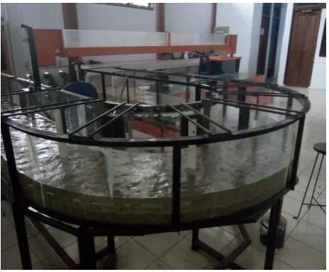
This research was conducted at the Hydraulics Laboratory of the Engineering Faculty at Tadulako University, from January to March 2017. The U-shaped channel (180o) was made of acrylic material, with a width of 0.5
Fig. 1. Water flow circulation scheme.
Fig. 2. Flume bend of 180o, width of 0.5 m and radius of 0.75 m.
Water was pumped from a reservoir 3 meters high in order to maintain water circulation in the device. The second reservoir flowed through a pipeline to the channel according to the discharge requirements. The excess discharge from this reservoir was flowed back to the first reservoir to allow the flow discharge in the fixed channel. The height of the water in the channel was controlled by the downstream door, which connected back to the first reservoir, as seen in Fig. 1. This figure shows the following:
1. Reservoir 1, which serves as the starting point of circulation
2. Water pump and flow generator, with a capacity of 1300 liters per minute 3. Input pipe from the pump to reservoir 2
4. Reservoir 2 at high pressure
5. Overflow pipe, which serves to stabilize the hydrostatic pressure 6. Inflow pipe to the model channel
7. Stop faucet installed to manage inflow discharge
8. Flume 0.5 m wide, 2 m initial straight channel, bends with a radius = 0.75 m, straight channel to outflow 3 m
9. Downstream door, which serves to set the height of the water 10. Outflow pipe
11. Pillar in the channel bend, which is moved and installed in increments of 60o, for both cylindrical and
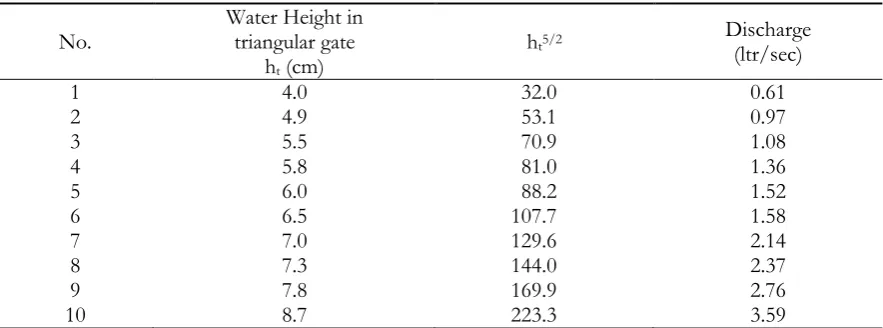
[image:3.595.207.389.76.268.2] [image:3.595.179.412.304.496.2]The initial measurements were conducted by measuring the discharge passing through the triangular door on the downstream model channel; these results can be found in Table 1.
Table 1. Relationship between water height and discharge.
No. Water Height intriangular gate ht (cm)
ht5/2 Discharge(ltr/sec)
1 4.0 32.0 0.61
2 4.9 53.1 0.97
3 5.5 70.9 1.08
4 5.8 81.0 1.36
5 6.0 88.2 1.52
6 6.5 107.7 1.58
7 7.0 129.6 2.14
8 7.3 144.0 2.37
9 7.8 169.9 2.76
10 8.7 223.3 3.59
Based on the data in Table 1, a simple regression analysis was conducted regarding the discharge equation (Eq.(1)).
Q = 1.589 ht5/2 with R2 = 0.994 (1)
The water discharge that streamed through the flume used the triangular door in the downstream flume. The triangular door was important for the height of the water that passed through it. The water height (ht) at
the triangular door was 13.5 cm. The ht(m) value was substituted into Eq.(1) to obtain the discharge (Q) of
0.01064 m3/sec or 10.64 ltr/sec. Considering this discharge, the average water height (h) in a straight line was
86.9 mm, from which we obtained the average velocity of the flow (u), which was 0.24 m/sec. The boundary condition of this study used equation as follows [9].
1 / 5 .
0 u uc (2)
This formula (2) shows that the local scouring occurred but that the sediment transport process did not. The value of the sediment critical velocity (uc) is obtained with the formula issued by The Wuhan Institute
of Hydraulic and Electric Engineering [16].
2 / 1 72 . 0 7 14 . 0 10 10 05 . 6 6 . 17 D h x D D h u s c (3)
where: uc = sediment critical velocity, g = gravity force, D = sedimentary diameter, h = height of water, γ =
weight of water content, and γs = weight of sediment content.
The value of D was calculated by Eq.(3) to satisfy Eq.(2), so that uc = 0.34 m/sec and D = 2.36 mm.
Another requirement for identifying the subcritical-turbulent flow was testing the flow based on the Froude (Fr) and Reynolds (Re) numbers as follows (Eq.(4) and (5)) [5].
gR u
Fr (4)
where: Fr = Froude number, u = velocity of flow, g = gravity force, and R = hydraulic radius (A/P), A =
[image:4.595.75.517.140.304.2] R u
Re (5)
where: Re = Reynolds number, u = velocity of flow, R = hydraulic radius, ν = kinematic viscosity.
By substituting the flow values in equations 4 and 5, it is clear that Fr = 0.46 <1 (subcritical flow) and Re
= 16,589> 12,500 (turbulent flow).
This study used a cylindrical pillar 5 cm in diameter and a triangular pillar 5 cm in width. The choice of size was based on the research of Masjedi [12], which showed that pillar size should not exceed 10% of the channel width. If the pillar were to exceed this size, the narrowing effect would occur; it would therefore not be the centrifugal force that caused the rising of the water level on the outside of the channel bend. The cylindrical and triangular pillars were moved in increments of 60o, from 0o to 180o, and the pillars were
installed simultaneously at bends of 0o, 60o, 120o, and 30o, 90o, 150o, so that both pillar shapes were placed in
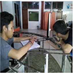
the six coordinates. The water height was measured with an accuracy of 0.1 mm (Fig. 3). Measurements were taken from 0.5 m before and after the bend and at increments of 30o, from 0o to 180o (Fig. 4). Figure 4
explains the measurements in each cross-section of the 7 points in a transverse direction, starting from point 1 to point 7.
[image:5.595.171.425.290.544.2]Fig. 4. Coordinate measurements.
3.
Results and Discussion
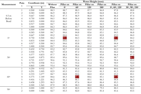
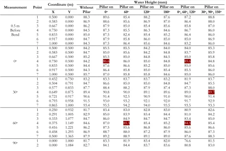
The measurements of the water height without pillars and with cylindrical pillars placed at various bends are shown in Table 2.
Table 2. Measurement of water height without and with cylindrical pillars.
Measurement Point Coordinate (m)
Water Height (mm) Without
Pilar Pillar on Pillar on Pillar on Pillar on Pillar on Pillar on X Y 0o 60o 120o 180o 0o, 60o, 120o 30o, 90o, 150o
1 0.500 0.000 88.3 88.7 88.3 87.7 86.8 87.8 88.8
2 0.583 0.000 86.9 88.3 87.9 86.8 84.8 86.2 87.8
0.5 m 3 0.667 0.000 86.2 87.3 86.9 86.0 84.9 86.4 87.4
Before 4 0.750 0.000 84.5 86.0 86.4 86.0 86.0 85.4 86.0
Bend 5 0.833 0.000 85.0 86.0 85.9 85.4 85.0 85.5 85.9
6 0.917 0.000 84.7 86.0 86.6 83.9 84.5 84.6 86.0
7 1.000 0.000 84.3 86.0 85.7 86.0 84.8 85.8 86.0
0o
1 0.500 0.500 84.2 84.6 84.6 83.0 83.3 83.9 86.5
2 0.583 0.500 84.7 84.6 84.8 83.6 83.1 84.5 86.8
3 0.667 0.500 85.2 84.6 84.1 83.0 82.8 83.0 86.0
4 0.750 0.500 84.2 84.6 84.3 83.4 85.2 83.4 84.2
5 0.833 0.500 84.4 84.6 85.3 84.1 84.8 83.7 84.3
6 0.917 0.500 84.3 84.6 85.8 84.2 85.1 84.4 84.7
7 1.000 0.500 85.7 85.6 85.6 85.0 85.0 84.7 85.0
30o
1 0.432 0.750 83.2 82.7 83.8 82.0 81.5 82.3 83.0
2 0.504 0.791 84.7 85.8 87.2 84.7 83.6 84.2 86.4
3 0.577 0.833 87.7 88.3 88.4 86.8 85.8 86.4 87.2
4 0.649 0.875 89.4 89.6 90.1 87.7 89.6 88.7 88.1
5 0.721 0.917 90.6 91.1 91.6 89.3 90.7 90.4 89.0
6 0.793 0.958 91.5 92.3 93.4 91.4 92.3 90.9 92.0
7 0.865 1.000 93.4 94.0 94.8 93.0 93.8 93.6 92.9
60o
1 0.250 0.932 81.7 81.3 81.6 81.8 80.8 80.6 84.0
2 0.291 1.005 82.9 83.3 83.2 83.0 81.3 81.3 85.0
3 0.333 1.077 84.7 84.8 84.6 84.0 83.0 83.2 85.1
4 0.375 1.149 84.6 85.3 85.4 84.6 85.1 83.8 86.0
5 0.416 1.221 86.2 86.3 86.1 85.1 86.3 84.4 86.2
6 0.458 1.293 86.9 87.3 87.6 86.4 86.4 85.3 86.8
7 0.500 1.365 87.9 88.3 88.3 88.0 88.4 86.8 88.3
90o 1 0.000 1.000 81.7 81.9 80.5 80.5 79.3 80.3 82.2
7 6 5 4 3 2 7 6 5 4 3 2 76 54 3 2 7 5 3 2 1 7 6 4 3 2 1 00 300 600 900 1200 1500 1800
0.5 m after bend 0.5 m before bend12345 67 5 4 6 1 1 1 5 6 4 3 2 1 7 3 2 4 5 6 7 1 3 2 4 5 6 7 1
2.0 m after bend
3.0 m before bend 0.5 m
0.0 Axis Y Axis X
[image:6.595.235.368.90.335.2] [image:6.595.74.535.466.773.2]3 0.000 1.167 84.7 84.6 84.3 84.0 83.8 82.4 85.4
4 0.000 1.250 85.7 87.3 87.0 86.3 86.8 86.2 85.7
5 0.000 1.334 87.8 88.8 88.6 87.8 88.8 87.8 86.0
6 0.000 1.417 89.9 90.3 88.8 90.0 90.6 88.8 88.5
7 0.000 1.500 92.2 91.9 91.6 91.4 91.9 91.0 90.7
120o
1 -0.250 0.932 81.0 80.8 80.6 81.0 81.4 79.8 82.9
2 -0.291 1.005 82.7 82.3 81.4 81.8 81.6 81.2 83.3
3 -0.333 1.077 84.7 83.3 84.3 83.8 83.7 81.9 85.7
4 -0.374 1.149 85.3 85.8 86.2 85.2 86.5 83.8 84.9
5 -0.416 1.221 86.5 88.3 88.1 86.5 88.8 85.6 87.4
6 -0.458 1.293 89.3 90.1 89.7 88.6 90.7 87.4 88.8
7 -0.500 1.365 91.7 91.9 91.3 91.4 91.8 90.4 91.1
150o
1 -0.432 0.750 80.4 81.3 81.3 81.0 81.4 79.4 82.5
2 -0.504 0.791 82.4 82.9 81.6 82.0 82.8 82.2 83.5
3 -0.576 0.833 83.9 84.3 83.4 83.7 83.8 83.5 84.9
4 -0.648 0.875 84.6 86.3 85.6 85.7 86.6 85.5 85.3
5 -0.721 0.917 87.5 88.3 88.1 87.0 88.4 87.0 85.7
6 -0.793 0.958 89.6 90.1 89.6 89.3 90.2 87.8 88.0
7 -0.865 1.000 91.7 91.3 90.8 90.8 91.7 90.0 90.2
180o
1 -0.500 0.500 81.0 81.1 81.6 81.8 80.9 80.6 81.1
2 -0.583 0.500 81.4 82.8 81.8 81.9 82.6 81.4 82.1
3 -0.667 0.500 82.4 83.3 82.6 82.0 83.4 82.5 83.6
4 -0.750 0.500 82.6 83.8 83.8 83.1 83.9 82.8 83.3
5 -0.833 0.500 83.9 85.3 84.6 84.0 84.4 84.1 84.0
6 -0.917 0.500 85.3 86.5 86.1 85.2 86.2 84.8 85.5
7 -1.000 0.500 87.4 88.5 87.8 87.2 87.4 86.6 87.0
1 -0.500 0.000 80.2 81.8 81.1 81.5 82.2 81.4 80.1
2 -0.583 0.000 80.7 81.8 80.6 80.8 80.7 80.4 81.0
0.5 m 3 -0.667 0.000 79.7 81.8 81.5 81.2 81.7 80.9 80.6
After 4 -0.750 0.000 79.4 81.8 81.8 81.7 81.2 81.0 81.0
Bend 5 -0.833 0.000 79.7 81.8 80.8 82.0 81.6 81.2 80.2
6 -0.917 0.000 80.2 81.8 81.6 81.4 82.0 81.3 81.1
7 -1.000 0.000 81.7 82.8 82.9 81.9 82.5 81.2 82.0
Note: number = coordinates of pillars.
The measurements of the water height without pillars and with triangular pillars placed at various bends are shown in Table 3.
Table 3. Measurement of water height without and with triangular pillars.
Measurement Point Coordinate (m)
Water Height (mm) Without
Pilar
Pillar on Pillar on Pillar on Pillar on Pillar on Pillar on X Y 0o 60o 120o 180o 0o, 60o, 120o 30o, 90o, 150o
1 0.500 0.000 88.3 89.6 85.4 88.2 87.6 87.2 88.8
2 0.583 0.000 86.9 88.6 85.6 86.9 87.0 86.4 88.0
0.5 m 3 0.667 0.000 86.2 87.9 85.0 85.4 85.6 85.8 87.0
Before 4 0.750 0.000 84.5 87.3 85.5 86.3 84.6 86.7 86.0
Bend 5 0.833 0.000 85.0 87.5 82.4 85.4 85.2 86.4 86.0
6 0.917 0.000 84.7 87.9 85.8 86.0 85.0 85.0 86.9
7 1.000 0.000 84.3 87.5 86.4 85.6 84.6 83.2 86.0
0o
1 0.500 0.500 84.2 85.5 85.5 84.2 84.0 84.0 85.3
2 0.583 0.500 84.7 85.0 85.6 84.2 84.8 83.7 85.9
3 0.667 0.500 85.2 85.5 85.0 84.8 84.5 85.0 85.8
4 0.750 0.500 84.2 86.6 86.0 85.0 84.8 85.6 84.8
5 0.833 0.500 84.4 87.6 86.6 85.2 85.0 85.0 85.6
6 0.917 0.500 84.3 86.4 85.8 85.0 85.4 85.5 86.0
7 1.000 0.500 85.7 87.0 85.8 85.8 84.6 85.0 86.0
30o
1 0.432 0.750 83.2 83.3 83.7 83.7 83.2 81.9 83.7
2 0.504 0.791 84.7 86.6 85.0 85.0 84.8 84.7 85.5
3 0.577 0.833 87.7 88.4 88.2 87.9 87.4 87.3 88.0
4 0.649 0.875 89.4 90.8 90.0 89.1 89.6 89.0 89.7
5 0.721 0.917 90.6 91.4 92.5 90.9 91.0 90.0 91.4
6 0.793 0.958 91.5 93.0 93.2 92.1 92.0 91.7 92.9
7 0.865 1.000 93.4 95.5 94.2 94.0 93.5 93.5 93.3
60o
1 0.250 0.932 81.7 83.4 83.0 82.8 83.0 80.9 82.6
2 0.291 1.005 82.9 85.0 83.9 83.4 84.4 81.0 84.2
3 0.333 1.077 84.7 86.0 84.9 84.7 84.7 83.4 85.0
4 0.375 1.149 84.6 87.0 85.3 85.4 85.2 84.5 85.4
5 0.416 1.221 86.2 87.5 85.6 86.8 86.0 85.6 86.6
6 0.458 1.293 86.9 88.7 88.0 87.2 87.9 86.0 87.3
7 0.500 1.365 87.9 89.2 88.9 89.1 89.0 87.6 88.3
[image:7.595.73.536.466.776.2]3 0.000 1.167 84.7 85.6 86.0 85.0 83.8 83.9 84.8
4 0.000 1.250 85.7 87.6 88.0 87.1 87.4 86.0 86.2
5 0.000 1.334 87.8 89.0 88.7 89.0 88.5 87.8 87.5
6 0.000 1.417 89.9 91.0 90.5 90.6 90.7 89.0 89.3
7 0.000 1.500 92.2 91.2 92.1 92.0 92.2 91.0 91.4
120o
1 -0.250 0.932 81.0 82.5 82.0 82.0 82.0 80.0 81.6
2 -0.291 1.005 82.7 84.1 83.7 83.3 83.6 81.9 83.1
3 -0.333 1.077 84.7 85.4 84.5 85.3 84.0 83.7 85.0
4 -0.374 1.149 85.3 87.0 87.0 86.4 86.0 85.2 87.0
5 -0.416 1.221 86.5 89.4 89.5 87.4 88.0 86.7 87.6
6 -0.458 1.293 89.3 91.0 90.8 90.7 90.1 89.0 89.5
7 -0.500 1.365 91.7 92.8 92.9 91.9 92.6 90.5 91.0
150o
1 -0.432 0.750 80.4 82.9 83.4 81.7 81.6 79.0 80.0
2 -0.504 0.791 82.4 83.4 85.2 82.9 83.6 81.3 83.0
3 -0.576 0.833 83.9 85.6 86.6 84.7 84.9 82.8 84.1
4 -0.648 0.875 84.6 86.9 87.8 86.3 87.0 85.7 85.3
5 -0.721 0.917 87.5 89.2 89.6 87.7 88.7 87.0 86.5
6 -0.793 0.958 89.6 90.0 91.0 89.2 90.0 89.0 89.0
7 -0.865 1.000 91.7 92.0 92.0 91.0 91.5 90.1 89.7
180o
1 -0.500 0.500 81.0 84.0 84.0 81.9 81.3 80.0 80.7
2 -0.583 0.500 81.4 83.0 84.2 82.5 83.0 80.9 81.7
3 -0.667 0.500 82.4 84.6 84.6 83.2 82.7 81.9 82.5
4 -0.750 0.500 82.6 86.0 84.8 84.3 83.8 83.7 83.3
5 -0.833 0.500 83.9 86.0 86.0 84.9 84.9 85.0 84.6
6 -0.917 0.500 85.3 87.0 88.0 86.4 86.4 85.8 86.0
7 -1.000 0.500 87.4 88.2 88.2 83.0 88.6 87.4 87.3
1 -0.500 0.000 80.2 83.4 83.6 82.3 81.0 81.0 81.6
2 -0.583 0.000 80.7 83.2 83.7 82.5 81.2 79.8 81.0
0.5 m 3 -0.667 0.000 79.7 83.2 83.7 82.0 81.0 80.0 81.7
after 4 -0.750 0.000 79.4 81.6 83.5 82.5 80.8 81.0 81.4
bend 5 -0.833 0.000 79.7 82.0 83.5 82.0 81.0 81.4 82.0
6 -0.917 0.000 80.2 82.0 84.2 82.1 81.2 81.5 82.0
7 -1.000 0.000 81.7 82.7 84.6 83.8 81.8 81.8 82.7
[image:8.595.73.533.69.392.2] [image:8.595.73.534.76.389.2]Note: number = coordinates of pillars.
Figure 5 shows the maximum water height that occurred at a bend of 30o, based on Tables 2 and 3.
[image:8.595.151.445.429.712.2]Fig. 5. Maximum water height with and without pillars.
Figure 5 shows the maximum water level in all three situations at a bend of 30o. The maximum water
mm. This value was used as a basis for analyzing the changes in the water level due to the effects of cylindrical and triangular pillars installed in the channel bend.
The cylindrical pillar installed at a bend of 0o produced a maximum water height of 94.0 mm on the outer
side of the bend and 82.7 mm on the inner side, with a difference of 11.3 mm. The triangular pillar produced a maximum water height of 95.5 mm on the outer side of the bend and 83.3 mm on the inner side, with a difference of 12.2 mm. The triangular pillar produced a higher maximum water height on the outer side of the bend than the cylindrical pillar. This was because of the velocity distribution at the cross-section when the maximum straight flow occurred in the middle of the flow [5, 17-18]. The side of the triangle steered the flow, so the water on the outer side was higher after passing by the pillar. The maximum water height without pillars was lower.
The cylindrical pillar installed at a bend of 60o produced a maximum water height of 94.8 mm on the
outer side and 83.8 mm on the inner side, with a difference of 10.0 mm. The triangular pillar produced a maximum water height of 94.2 mm on the outer side of the bend and 83.7 mm on the inner side, with a difference of 10.5 mm. Of the two types of pillars installed at a bend of 60o, the changes on the outer side of
the bend were smaller than if the pillars were installed at a bend of 0o. The water height was still higher than
it was without a pillar.
The cylindrical pillar installed at a bend of 120o produced a maximum water height of 93.0 mm on the
outer side of the bend and 82.0 mm on the inner side, with a difference of 11.0 mm. The triangular pillar produced a maximum water height of 94.0 mm on the outer side of the bend and 83.7 mm on the inner side, with a difference of 10.3 mm. The change in the water height when the pillar was installed at a bend of 120o
was smaller than if the pillars were installed at bends of 0o or 60o. The water height was lower when with a
cylindrical pillar than without a pillar, but higher when with a triangular pillar.
The cylindrical pillar installed at a bend of 180o produced a maximum water height of 93.8 mm on the
outer side of the bend and 81.5 mm on the inner side, with a difference of 12.3 mm. The triangular pillar produced a maximum water height of 93.5 mm on the outer side of the bend and 83.2 mm on the inner side, with a difference of 10.3 mm. The placement of the two types of pillars at a bend of 180o produced a
maximum water height on the outer side of the bend that was comparable to that without a pillar.
The cylindrical pillar installed simultaneously at bends of 0o, 60o, 120o produced a maximum water height
of 93.6 mm on the outer side of the bend and 82.3 mm on the inner side, with a difference of 11.3 mm. The triangular pillar produced a maximum water height of 93.5 mm on the outer side of the bend and 81.9 mm on the inner side, with a difference of 11.6 mm. The placement of the pillar at bends of 0o, 60o, 120o produced
a maximum water height on the outer side of the bend that was similar to the flow without a pillar.
The cylindrical pillar installed simultaneously at bends of 30o, 90o, 150o produced a maximum water
height of 92.9 mm on the outer side of the bend and 83.0 mm on the inner side, with a difference of 9.9 mm. The triangular pillar produced a maximum water height of 93.3 mm on the outer side of the bend and 83.7 mm on the inner side, with a difference of 9.6 mm. The placement of pillar at bends of 30o, 90o, 150o produced
a maximum water height on the outer side of the bend that was similar to the flow without a pillar.
This research indicates that the pillar shape affects the maximum water height on the outer side of the bend. The increase in the maximum water height is directly proportional to the average water velocity, gravity force, river width, bend radius, and superelevation coefficient [4, 15].
This research could be used as a reference for the construction of pillars used in bridges that are built on river bends, particularly bridges with two spans, with one pillar in the river. The maximum height of the dike occurred at a bend of 30o, either with or without a pillar.
Triangular pillars installed at bends of 0o or 120o or installed simultaneously at bends of 30o, 90o, 150o
produced the maximum water height. This signifies that, if there is a bridge pillar at a river bend, it is more economical to use a cylindrical pillar in order to maintain the height of the dike on the outer side. Cylindrical pillars installed at bends of 60o or 180o or installed simultaneously at bends of 0o, 60o, 120o produced the
maximum water height. This indicates that it is more economical to use a triangular pillar to maintain the height of the dike on the outer side.
4.
Conclusions
The cylindrical and triangular pillars affected the maximum water height on the outer side of the river bend and the maximum water height always occurred at a channel bend of 30o. Bridge pillars installed at bends of
cylindrical pillars. If installed at bends of 60o or 180o or installed simultaneously at bends of 0o, 60o, 120o, they
were more economical if they were triangular pillars.
References
[1] R. Ghobadian and K. Mohammadi, “Simulation of subcritical flow pattern in 180° uniform and convergent open-channel bends using SSIIM 3-D model,” Water Science and Engineering, vol. 4, no. 3, pp. 270-283, 2011.
[2] J. Mozaffari, E. A. Tokaldany, and Blanckaert, “Exprimental investigations to determine the distribution of longitudinal velocity in rivers bends,” Research Journal of Environmental Sciences, vol. 5, no. 6, pp. 544-556, 2011.
[3] M. G. Ishak, “The effect of thickness of pillar in the channel bend to changes the coefficient of superelevation,” Journal of Engineering Science and Technology, vol. 11, no. 5, pp. 745–754, 2016.
[4] C. L. Yen and B. C. Yen, “Water surface configuration in channel bends,” Journal of the Hydraulics Division, vol. 97, no. 2, pp. 303-321, pp. 303-321, 1971.
[5] V. T. Chow, Open Channel Hydraulics, 2nd ed. Bandung, Indonesia: Erlangga, 1989.
[6] U. Ukiman, R. Y. Kondoatie, and S. Sriyana, “Study the basic configuration of channels in bend 90°,” Pillar, vol. 15, no. 1, pp. 1–13, 2006.
[7] M. G. Ishak and I. G. Tunas, “Flow analysis on the bend of channels (physical and mathematical model study to explain the scouring phenomenon in Palu River),” Journal MEKTEK, vol. 10, no. 3, pp. 140-146, 2008.
[8] J. G. Duan, “Simulation of flow and mass dispersion in meandering channels,” Journal of Hydraulic Engineering, vol. 130, no. 10, pp. 964-976, 2004.
[9] A. Wiyono, I. Soekarno, and A. Egon, “Comparison of calculation some formula scours around pillar (laboratory studies),” Journal of Civil Engineering, vol. 13, no. 1, pp. 41-54, 2006.
[10] R. I. Ferguson, D. R. Parsons, S. N. Lane, and R. J. Hardy, “Flow in meander bends with recirculation at the inner bank,” Water Resources Research, vol. 39, no. 11, pp. 1-13, 2003.
[11] T. J. Randle, “Channel migration model for meandering rivers,” in Proceedings of the Eighth Federal Interagency Sedimentation Conference (8th Fisc), April 2-6, 2006, Reno, NV, USA, pp. 241-248. Available: https://pubs.usgs.gov/misc/FISC_1947-2006/pdf/1st-7thFISCs-CD/8thFISC/Session%204B-2_Randle.pdf [Accessed: January 11, 2017]
[12] A. Masjedi, H. Kazemi, and E. P. Foroushani, “Experimental study on the effect of cylindrical bridge pier position on the scoring depth in the rivers bend,” in the33rd IAHR Congress: Water Engineering for a Sustainable Environment, 2009, pp. 4539-4545.
[13] N. Kardan, H. Hakimzadeh, and Y. Hassanzadeh, “Investigation of the dynamics bed shear stress distribution around a circular cylinder using various turbulences models,” Engineering Journal, vol. 21, no. 7, pp. 75-86, 2017.
[14] M. G. Ishak, “Coefficient of superelevation for the flow using movable pillar in channel bend,” International Journal of Engineering and Technology, vol. 7, no. 6, pp. 63-69, 2015.
[15] E. Kasvi, L. Laamanen, E. Lotsari, and P. Alho, “Flow patterns and morphological changes in a sandy meander bend during a flood—Spatially and temporally intensive ADCP measurement approach,” Water, vol. 9, no. 106, pp. 1-20, 2017.
[16] Y. Xiaoqing, “Manual on sediment management and measurement,” World Meteorological Organization, Genewa, Switzerland, Operational Hydrology Report No. 47, 2003.
[17] L. C. van Rijn, Principles of Fluid Flow and Surface Waves in Rivers, Estuaries, Seas, and Oceans. The Netherlands: Aqua Publications, 1990.