Article
Analysis of Multi-objective Optimal Dispatch of
Cogeneration with Thermal Energy Storage for
Building Energy Management System
Kebsiri Manusilp
aand David Banjerdpongchai
bDepartment of Electrical Engineering, Faculty of Engineering, Chulalongkorn University, 254 Phayathai Road, Pathumwan, Bangkok, 10330 Thailand
E-mail: a[email protected], b[email protected] (Corresponding author)
Abstract. This paper presents analysis of the multi-objective optimal operation of designed BEMS which contains cogeneration or combined heat and power (CHP) and thermal energy storage (TES) as energy sources. The previously designed BEMS consists of CHP as the main energy supply with absorption chiller and auxiliary boiler. It is observed that there is excessive heat energy from CHP operation which is enough for further utilization. In this paper, TES is additional component to utilize excessive heat energy released from CHP operation. TES cooperates with CHP and auxiliary boiler to supply heat energy to meet the cooling load demand in the building. There are two objective functions for consideration, namely, total operating cost (TOC) and total carbon dioxide emission (TCOE). The multi-objective framework combines both objective functions and employs the weighted sum of TOC and TCOE. Furthermore, we vary initial state of TES from 0-20% of TES’s capacity and analyze its effect on TOC and TCOE. We apply the multi-objective approach to a large shopping mall. Numerical results show that setting initial state of TES to 0% can offer more reduction of TOC and TCOE than other initial conditions. The multi-objective optimal operation converges to minimum TOC when a weighting factor is 0. On the other hand, it converges to the minimum TCOE when the weighting factor is 1. In addition, the trade-off curve showing a relationship between TOC and TCOE provides operating points which depends on operator’s decision criterion.
Keywords: Combined heat and power (CHP), thermal energy storage (TES), building energy management system (BEMS), multi-objective approach, energy efficiency.
ENGINEERING JOURNAL Volume 21 Issue 5 Received 6 January 2017
1.
Introduction
Building energy management system (BEMS) has become popular research topic for many years due to limitation of energy source and rising trends of energy consumption. Besides, the main electricity usage in the building generally comes from power grids which provide high price of electricity charge depending on on/off peak hour and also generates high carbon dioxide (CO2) emission to atmosphere. Generally,
conventional buildings such as offices, commercial buildings, shopping malls, hotels, or homes contain mainly three types of load, i.e., electrical, cooling, and heating loads. Both public and private sectors always seek solution for energy efficiency usage management such as seeking other energy sources, implementing network management, design of smart grid [1-5]. One of the promising technologies usually applies with BEMS is Cogeneration or combined heat and power (CHP).
CHP is simultaneous production of heat and power [6-7]. CHP employs only a single source to obtain two types of output which heat energy is from fuel combustion in process. Besides, CHP is promoted as an energy source in Thailand Power Development plan (PDP2015) [8] since it offers more efficiency than conventional generation. Therefore, many researches focus on how to apply CHP to BEMS. Not only CHP system but solar and conventional energy sources are often implemented to supply to energy demand in commercial building. The goal is to minimize the life-cycle cost and profits from exporting onsite-generated electrical energy to grids [9]. Economic operation of CHP is designed under emission constraints in order to minimize the cost and pollutant emission from CHP system [10]. There is model development to achieve optimal dispatch of electrical, cooling, and heating supply to load in a small industry. In particular, economic operation aims to reduce investment cost and time, and gain more benefits and comfort [11]. Subsequently, the CHP model is modified to suit application of a large shopping mall [12]. The modified model consists of CHP cooperating with boiler and chiller to respond the electrical and cooling loads in the shopping mall. It is observed that there is some excessive heat energy releases from CHP to the atmosphere. The amount of excessive heat is enough for further utilization. Therefore, thermal energy storage (TES) is installed to utilize excessive heat energy from CHP operation and dispatch strategy is designed by taking into account of TES constraints [13]. The installed TES cooperates with CHP and the boiler to supply enough heat energy to meet the demand in the building. Objective functions are to minimize total operating cost (TOC) and total CO2 emission (TCOE) of BEMS. As a result, CHP with TES can offer reduction of
TOC and TCOE since TES can reduce operation of the boiler. However, relationship of two objective functions has not been investigated.
In this paper, we propose a multi-objective optimal operation of CHP with TES in order to find the relationship between economic and environmental optimal operations. Furthermore, we will analyze the effect of the multi-objective operation when initial state of TES is varied. Optimal operation is described in terms of trade-off relationship between TOC and TCOE. The results will enable the operator to select the preferred operating point.
This paper is organized as follows. Section 2 is system description of the proposed CHP with TES. Section 3 presents objective functions and mathematic model of TES. The energy dispatch strategies of both electrical and cooling energy are presented in section 4. System parameters and load profile of test system is in Section 5. Section 6 illustrates the trade-off results. Conclusions are given in section 7.
2.
Cogeneration with Thermal Energy Storage for Building Energy Management System
Generally, conventional buildings employ electrical energy from power grids in order to response load demands in the buildings. Power grids require high electricity charges, especially on-peak hours and most of supply-side power plants still use fossil fuel which cause large amount of CO2 emission to the atmosphere.
Therefore, the goal of designed cogeneration system is to reduce operating cost and CO2 emission. The
cogeneration or CHP becomes part of the system as an efficient energy source. As excessive thermal energy is found from CHP operation in previous research [12], thermal energy storage is installed to utilize the excessive thermal energy [13]. Accordingly, the proposed BEMS consists of a CHP system, an auxiliary boiler, an absorption chiller, and a thermal energy storage (TES) an energy supplies of BEMS.
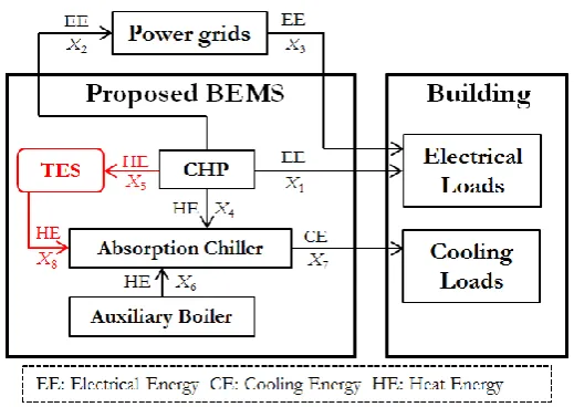
Fig. 1. Diagram of CHP and TES in response to load demands of building.
CHP mainly supplies energy to meet energy load demands in the building due to the production of simultaneous electrical and heat energy. In this study, BEMS is connected to power grids for power trading. Imported electrical energy from power grids is needed when CHP cannot adequately supply to demand loads. BEMS can earn revenues from exporting excessive electrical energy to power grids. Since heat energy is produced by CHP, the absorption chiller is equipment which converts heat energy to cooling energy then supplies to the cooling load in the building. Moreover, the auxiliary boiler plays a role of supplying heat energy in case that CHP cannot fulfill the demand load. In some cases, CHP generates heat energy but there is no cooling load. This heat energy will be stored in TES. When CHP and auxiliary boiler cannot supply enough heat energy to meet the demand, TES will cooperate to supply heat energy to absorption chiller.
3.
Problem Formulation
The goal of cogeneration system is to achieve reductions of energy operating cost and CO2 emission by
applying TES. Optimal dispatch strategy is formulated by applying two objective functions. Concerning issues of energy cost and CO2 emission, economic and environmental optimal operations are separately
considered and subject to operating constraints of CHP and other equipment including TES. All physical components are modeled as linear function and neglecting internal losses.
3.1. Economic Optimal Operation
The economic optimal operation is objective function which aims to minimize total operating cost, TOC (baht). TOC is a result from the sum of energy cost (EC) and demand charge cost (DCC). EC is the sum of energy operating cost from components which can be calculated from energy cost of CHP, income and expense from power trading with power grids, and energy cost of the auxiliary boiler. DCC is calculated from maximum imported power from power grids of the whole interested periods. The economic optimal operation can be represented as follows.
DCC + EC =
TOC (1)
∑
-nd
1 =
k (CCHP(x1,k +x2,k) qkx2,k +pkx3,k+cABx6,k)
=
EC (2)
k , 3 nd ,..., 1 = h
PG max x
t Δ d = DCC
(3)
where xi,k is energy flow (MWh) following Fig. 1 in time interval of k. cCHP and cAB are operating cost of
[image:3.595.166.426.79.263.2]is electrical energy charge price during on-peak and off-peak hour, dPG is demand charge depending on
maximum imported power from power grids, n is the number of time interval in one day, d is the number of days, and ∆t is time duration of each time interval.
3.2. Environmental Optimal Operation
Effective BEMS concerns not only the operation cost, but also greenhouse gas emission. The environmental optimal operation aims to minimize CO2 emission which is defined in terms of total carbon
dioxide emission, TCOE (tonCO2). TCOE is calculated from the sum of CO2 emission of electrical energy
production process of CHP, imported power from power grids, and heat energy production process of the auxiliary boiler. The environmental optimal operation can be represented as follows.
)) x ( ∑ η EF + ) x ( GEF + ) x + x ( EF ( =
TCOE nd 6,k
1 = k AB CO , AB k , 3 k , 2 k , 1 CO ,
CHP 2 2 (4)
where EFCHP,CO2 and EFAB,CO2 are CO2 emission factors of CHP and auxiliary boiler operations. These
factors depend on fuel price. GEF is grid emission factor and 𝜂AB is boiler’s efficiency.
3.3. Multi-objective Optimal Operation
Since two objective functions are important, we can combine both economic and environmental optimal operations by employing a weighting factor )( and normalization of objective functions. A multi-objective α function denoted by J is defined as follows.
min min TCOE TCOE α TOC TOC α) -(1
J (5)
The weighting factor is constant real number and varies from 0 to 1. Minimizing (5) will result in a multi-objective optimal operation.
TOC
minis the minimum of TOC, andTCOE
min is the minimum ofTCOE.
3.4. Thermal Energy Storage Model
TES is equipment used to store excessive heat from CHP and supply heat energy to the building load. The mathematic model is based on Hashemi’s paper [11]. Heat charge and discharge shall not exceed (R1) and
discharge (R2) rates. Besides, state of charge of TES can be calculated from the difference of heat charge to
TES and heat discharge from TES. Constraints of TES can be described as follows:
1 k , 5 )≤R
x ( ε (6) 2 k , 8 )≤R
x ( δ 1 (7) 1 + j k k 1 =
j 5j, 8,k k
k ,
9 =init(1 μ) + (ε(x ) δ1(x ))(1 μ)
x - ∑ - - (8)
max k
, 9 min≤x ≤S
S (9)
where ε and δ are TES charge and discharge efficiency, R1 and R2 are charge and discharge rates. The
variable x9,k is state of charge at time k. Loss coefficient of TES is represented by μ . init is initial heat
energy stored in TES. Smin and Smax are minimum and maximum states of TES.
4.
Energy Dispatch Strategies
classified into two types, electrical energy (EE) dispatch and cooling energy (CE) dispatch. Optimization problem is formulated as a linear program (LP) which can be efficiently solved by LP solvers.
EE dispatch is a function of electrical load (Uk)in the building. Energy supplies compose of CHP and power grids. EE dispatch contains two conditions. Firstly, CHP will shut down when there is no U . On k the other hand, CHP and power grids supply EE to the load under limitations of minimum and maximum production of CHP (PCHP,min and PCHP,max). EE and HE production of CHP will be operated at power-to-heat ratio (P2H). Ramp rate of CHP is considered by the difference of EE generation in pervious and current states. The EE dispatch can be written as follows.
if Uk =0, then
0 = x = x = x =
x1,k 2,k 4,k 5,k else t P x x t
PCHP,minΔ ≤ 1,k + 2,k ≤ CHP,maxΔ
H 2 P = x + x x + x k , 5 k , 4 k , 2 k , 1 t Δ R ) x + x ( ) x + x
( 1,k 2,k - 1,k-1 2,k-2 ≤ CHP
end k k , 3 k ,
1 +x =U
x
For the CE dispatch, heat energy sources consist of CHP, the auxiliary boiler, and TES. All these components supply heat energy to the absorption chiller in order to convert into cooling energy for cooling load (Ck). The CE dispatch provides four conditions of heat/cooling energy management. Firstly, there is
no heat energy from any source to the chiller, but there is excessive heat charging to TES while CHP still runs the operation to meet electrical load. The excessive heat charging to TES is limited by charge rate (R1).
Secondly, there is cooling load Ck less than minimum cooling production of chiller (CPAC,min). CHP and
TES will supply HE to the chiller. The chiller operates at its minimum level to maintain temperature in the building. Therefore, there is no need to operate the boiler and there is no excessive heat charging to TES during discharging heat. Thirdly, when Ck is over minimum operation of the chiller and CHP supplies
enough heat, boiler will not be enabled. CHP and TES cooperate to supply HE to the chiller and covert to CE at level of Ck. Finally, when CHP does supply enough HE to meet Ck,, the auxiliary boiler has a role to
supply enough heat to the chiller in conjunction of CHP and TES operation. The chiller operates at Ck and
does not exceed the maximum cooling production of chiller (CPAC,max) and the heat production from CHP
and the boiler. The CE dispatch can be summarized as follows.
if Ck=0, then
0 = x = x = x =
x4,k 6,k 7,k 8,k ) μ 1 )( x + x ( =
x9,k 9,k-1 5,k
-t Δ R ≤ ) x (
ε 5,k 1 else if Ck ≤CPAC,minΔt, then
k , 7 AC k , 8 k ,
4 +x )COP =x
x ( t Δ R ≤ x δ 1 2 k , 8 ) μ 1 )( x x ( =
x9,k 9,k-1- 8,k
-0 = x = x5,k 6,k
t Δ CP
=
x7,k AC,min
elseif k CHP,max COPAC H 2 P t Δ P ≤
k , 7 AC k , 8 k ,
4 +x )COP =x
x ( t Δ R ≤ ) x ( δ 1 2 k , 8 ) μ 1 )( x x ( =
x9,k 9,k-1- 8,k
-0 = x = x5,k 6,k
) COP H 2 P t Δ P , C min( =
x7,k k CHP,max AC else k , 7 AC k , 8 k , 6 k ,
4 +x +x )COP =x
x ( t Δ R ≤ ) x ( δ 1 2 k , 8 ) μ 1 )( x x ( =
x9,k 9,k-1- 8,k
-t Δ HP ≤ x ≤ t Δ
HPAB,min 6,k AB,max 0
= x5,k
) COP ) t Δ HP + H 2 P t Δ P ( CP , C min( =
x7,k k AC,max CHP,max AB,max AC end.
The multi-objective optimal operation is formulated as a linear program (LP) which can be efficiently solved by LP solvers.
5.
System Parameters
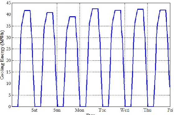
In case study, we consider load profiles of a large shopping mall in Bangkok, Thailand as a test system. Normally, the shopping mall utilizes the electricity from Metropolitan Electricity Authority (MEA) with 69-kV distribution grid. Figure 2 shows electrical load profile for 7 days ranging from 5 MW to 24 MW. Figure 3 shows calculated cooling load profile for 7 days ranging from 0 MW to 43 MW. Therefore, parameters of major components of BEMS are based on the test system of BEMS [12, 13].
[image:6.595.153.441.499.689.2]Fig. 3. Calculated cooling load profile of large shopping mall for 7 days.
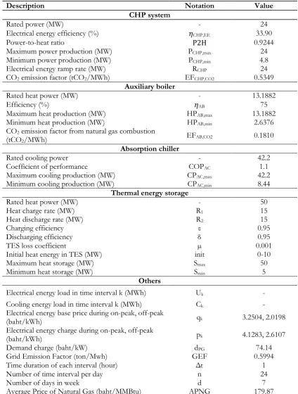
For CHP system, BEMS utilizes gas turbine as CHP system due to appropriate size and capacity with the demand. Gas turbine runs with high temperature steam which provides benefits to the cooling load of the building [7]. There is a research of TOC and TCOE by varying CHP size from 22 MW to 25 MW [12]. In our test system, electrical load profile has peak demand of 24 MW. Thus, we choose 24 MW of CHP. For the absorption chiller, double-effect absorption chiller 12,000-TR is selected which matches energy output of CHP system. Coefficient of Performance (COP) of chiller is 1.1 following regulation on energy usage for building recommendation [12]. For auxiliary boiler, industrial boiler using natural gas is chosen with capacity of 45 MMBtu/hr. Moreover, the boiler with natural gas can obtain 75% of thermal efficiency at full load [12, 14] and CO2 emission factor from natural gas combustion (EFAB,CO2) is 0.1810 tCO2 [15].
Natural gas price (baht/MMBtu) can be calculated following National Energy Policy Commission [16] as follows.
0654 . 12 + ) 4759 . 11 , APNG × 0933 . 0 min( + APNG =
NGP (10)
where APNG is monthly average of natural gas price (baht/MMBtu) which data can be found from the Department of Mineral Fuels, Ministry of Energy [17]. The second term is payment of natural gas supply and distribution depends on types of customer [16]. The last term is price of gas transportation [18].
In Thailand, there are two types of electricity price, i.e., time-of-day (TOD) and time-of-use (TOU). TOU rate is adopted in this study. TOU tariff composes of energy charge, demand charge, service charge, power factor charge, fuel adjustment (Ft), and VAT. However, only energy charge and demand charge are considered in this study and the rest are neglected. BEMS pays 4.1283 and 2.6107 baht/kWh for energy charge on-peak and off-peak time, respectively. The demand charge price for large general service with 69-kV is 74.14 baht/kW [19]. The selling price from CHP to power grid can refer from the wholesale prices that EGAT sells electricity to MEA [22]. Furthermore, electricity price from CHP is referred in [20]. For grid emission factor (GEF) of Thailand, CO2 emission is estimated when BEMS uses electricity from power
grids [21]. All parameter are summarized in Table 1.
6.
Numerical Results and Discussions
[image:7.595.158.438.79.263.2]Table 1. System parameters.
Description Notation Value
CHP system
Rated power (MW) - 24
Electrical energy efficiency (%) 𝜂CHP,EE 33.90
Power-to-heat ratio P2H 0.9244 Maximum power production (MW) PCHP,max 24
Minimum power production (MW) PCHP,min 4.8
Electrical energy ramp rate (MW) RCHP 24
CO2 emission factor (tCO2/MWh) EFCHP,CO2 0.5349 Auxiliary boiler
Rated heat power (MW) - 13.1882
Efficiency (%) 𝜂AB 75
Maximum heat production (MW) HPAB,max 13.1882
Minimum heat production (MW) HPAB,min 2.6376
CO2 emission factor from natural gas combustion
(tCO2/MWh) EFAB,CO2 0.1810 Absorption chiller
Rated cooling power - 42.2 Coefficient of performance COPAC 1.1
Maximum cooling production (MW) CPAC,max 42.2
Minimum cooling production (MW) CPAC,min 8.44 Thermal energy storage
Rated heat power (MW) - 50 Heat charge rate (MW) R1 15
Heat discharge rate (MW) R2 15
Charging efficiency ε 0.95 Discharging efficiency δ 0.95 TES loss coefficient µ 0.001 Initial heat energy in TES (MW) init 0-10 Maximum heat storage (MW) Smax 50
Minimum heat storage (MW) Smin 5 Others
Electrical energy load in time interval k (MWh) Uk -
Cooling energy load in time interval k (MWh) Ck -
Electrical energy base price during on-peak, off-peak
(baht/kWh) qk 3.2504, 2.0198 Electrical energy charge during on-peak, off-peak
(baht/kWh) pk 4.1283, 2.6107 Demand charge (baht/kW) dPG 74.14
Grid Emission Factor (ton/Mwh) GEF 0.5994 Time duration of each interval (hour) Δt 1 Number of time interval per day n 24 Number of days in week d 7 Average Price of Natural Gas (baht/MMBtu) APNG 179.87
6.1. Effect with TOC and TCOE from Initial State of Thermal Energy Storage
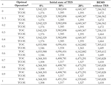
[image:8.595.84.509.103.664.2]causes TOC and TCOE increase. For instance, when α is chosen as 0.25, TOC for 0% initial state is 5,942,529 baht, TOC for 10% initial state is 5,982,898 baht, and TOC for 20% initial state is 6,049,307 baht. For BEMS without TES, TOC is 7,258,155 baht. Thus, BEMS with TES can reduce TOC from 16.7% to 18.1% compared to that of BEMS without TES. We observe a similar trend for environmental operation, namely, TCOE for 0% initial state is 1,576 tCO2, TCOE for 10% initial state is 1,585 tCO2, and TCOE for
20% initial state is 1,595 tCO2. For BEMS without TES, TCOE is 1,664 tCO2. Therefore, BEMS with TES
can reduce TCOE from 4.1% to 5.3% compared to that of BEMS without TES.
Based on results, it is observed that a lower initial state of TES offers much more reduction of TOC and TCOE for all choices of weighting factor (α). CHP normally generates electrical and heat energy based on P2H ratio. Importing electrical energy from power grids is an expensive option due to large impact on TOC and TCOE. Therefore, CHP has to produce electrical energy to supply electrical load for the first priority. Moreover, BEMS enables CHP not only to produce electrical energy for EE demand, but also coordinate with TES to manage excessive heat from CHP. In case of large initial state of TES, the remaining space for heat storage is small. If electrical energy generated by CHP is not sufficient to meet the EE demand, BEMS has to import electrical energy from power grids which will effect to TOC and TCOE.
The results in Table 2 confirm that for any choice of initial state of TES, increasing weighting factor α causes TOC increase but TCOE decrease. BEMS with TES yields significant improvement compared to that of BEMS without TES.
6.2. Relationship between TOC and TCOE
In this subsection, we analyze the relationship between economic optimal operation and environment optimal operation when we apply the objective optimal dispatch strategy to BEMS. The multi-objective function of Eq. (5) is minimized and we vary weighting factor α from 0 to 1 and initial state of TES from 0-20%. In numerical simulation, we select 2500 samples of α and determine the optimal objective function. Figure 4 shows the results of multi-objective optimal operation as function of weighting factor α and initial state of TES. It is observed that the multi-objective operation converges to economic optimal operation which yields minimum TOC when α = 0. On the other hand, the multi-objective operation converges to the environmental optimal operation which gives minimum TCOE when α = 1. Table 2 shows TOC and TCOE of the multi-objective operation by varying α and initial state of TES. It is noted that for a given initial state of TES, some values of α yield the same optimal TOC and TCOE.
[image:9.595.114.478.477.716.2]Table 2. TOC and TCOE by varying α and initial state of TES.
*Unit of TOC is baht and unit of TCOE is tCO2.
Figure 4 clearly displays trade-off relationship between TOC and TCOE and it depends on α and initial state of TES. The trade-off curve has twofold benefits. First, it is useful for operator to choose optimal operating points. For example, if we choose 10% of the initial state of TES (red line), TOC is specified to be less than 6.09 Million baht, then TCOE should range from 1,554 tonCO2 to 1,584 tonCO2. Second, it
provides the limit of performance of optimal operations. In particular, TOC will not be less than 5.94 Million baht, and TCOE will not be less than 1,508 tCO2.
6.3. Energy Flow Analysis of Multi-Objective Optimal Operation
This subsection shows energy flow analysis of multi-objective optimal operation of BEMS with TES. We demonstrate energy flow for the case α = 0.5 and initial state of TES equal to 0%. As a result, BEMS with multi-objective operation offers TOC equals to 6,055,988 baht and TCOE equals to 1,546 tonCO2 for load
profiles in a whole week. Moreover, BEMS with TES can reduce TOC up to 17.1% and TCOE up to 6.2% when compared to that of BEMS without TES.
For a chosen operating point, we demonstrate optimal energy flow in one day. BEMS with TES normally operates to meet load demands in the building. Therefore, electrical energy from CHP production is mainly supplied to the electrical load. Moreover, BEMS will earn profits from exporting of excessive electrical energy during on-peak hour as in Fig. 5. The main heat energy from CHP production is supplied to the chiller. During off-peak hours, excessive heat energy is charged to TES at 00.00 to 07.00 as shown in Fig. 6. The optimal energy flow to electrical load is referred in Fig. 7. CHP system is the main component which supplies most of generated electrical energy to electrical load. It is observed that there is imported electrical energy from power grid during 07.00-09.00 because price of electrical energy importing at that time offers advantage to the operating cost over running operation of CHP. Figure 8 shows optimal cooling energy flow to cooling load. During on-peak hours, CHP system is still the main component which supplies heat energy to the cooling load indirectly. Moreover, heat energy from TES can reduce operation of the
α Operation* Optimal 0% Initial state of TES 10% 20% without TES BEMS
0 TCOE TOC 5,942,529 1,576 5,982,898 1,585 6,049,307 1,595 7,246,962 1,672
0. 1 TCOE TOC 5,942,529 1,576 5,982,898 1,585 6,049,307 1,595 7,246,962 1,672
0.2 TCOE TOC 5,942,529 1,576 5,982,898 1,585 6,049,307 1,595 7,246,962 1,672
0.3 TCOE TOC 5,942,529 5,982,898 6,049,307 7,258,155 1,576 1,585 1,595 1,664 0.4 TCOE TOC 5,942,529 1,576 5,982,898 1,585 6,049,307 1,595 7,258,155 1,664
0.5 TCOE TOC 6,055,988 1,546 6,096,416 1,554 6,162,882 1,565 7,305,612 1,649
0.6 TCOE TOC 6,055,988 1,546 6,096,416 1,554 6,162,882 1,565 7,305,612 1,649
0.7 TCOE TOC 6,368,305 1,508 6,408,781 1,517 6,475,291 1,527 7,543,828 1,618
0.8 TCOE TOC 6,368,305 1,508 6,408,781 1,517 6,475,291 1,527 7,543,828 1,618
0.9 TCOE TOC 6,368,305 1,508 6,408,781 1,517 6,475,291 1,527 7,543,828 1,618
[image:10.595.84.511.110.439.2]boiler at on-peak hours which directly reduce TOC and TCOE compared to that of BEMS without TES. Figure 8 shows state of charge of TES, heat energy is charged to TES at 00.00-07.00. Afterwards during 7.00-17.00 and 22.00-24.00, heat energy is discharged from TES to supply heat together with CHP and the boiler. TES normally operates to charge and discharge to meet the cooling load demand in one day.
Fig. 5. Electrical energy production of CHP.
Fig. 6. Heat energy production of CHP.
[image:11.595.116.480.145.286.2] [image:11.595.123.472.327.468.2] [image:11.595.122.472.511.647.2]Fig. 8. Cooling energy flow to cooling load.
Fig. 9. State of charge of TES for multi-objective optimal operation.
7.
Conclusions
In this paper, thermal energy storage (TES) is additional component in BEMS and coordinates with CHP for the main energy supply. TES stores excessive thermal energy which is generated by CHP under condition of no cooling load. TES plays a role as an energy source which supplies heat energy to absorption chiller when there is cooling load. Adding TES to BEMS, multi-objective optimal operation is applied to BEMS in order to analyze relationship between two distinct objective functions, TOC and TCOE. The relationship between TOC and TCOE represented as a trade-off curve offers many optimal solutions depending on operator’s selection criterion. Moreover, varying initial state of TES gives a significant impact of TES on the multi-objective optimal operation. Lower level of initial state provides more reduction of TOC and TCOE.
References
[1] D. Lee and C. C. Cheng, “Energy saving by energy management systems: A review,” Renewable and
Sustainable Energy Reviews, vol. 56, pp.760-777, Nov. 2015.
[2] R. Missaoui, H. Joumaa, S. Ploix, and S. Bacha, “Managing energy Smart Homes according to energy prices: Analysis of a building energy management system,” Energy and Buildings, vol. 71, pp. 155-167, Dec. 2013.
[3] N. C. Batista, R. Melicio, J. C. O. Matias, and J. P. S. Catalao, “Photovoltaic and wind energy system monitoring and building/home energy management using ZigBEE devices within a smart grid,”
Energy, vol. 49, pp. 306-315, November, 2012.
[4] Z. Jiang and H. Rahimi-Eichi, “Design, modeling and simulation of a green building energy system,”
[image:12.595.113.473.84.215.2] [image:12.595.132.463.87.445.2] [image:12.595.145.452.250.443.2][5] D. Estates, “Building energy management systems,” in Her Majesty's Stationery Office, Ministry of Defense, United Kingdom, Jan. 2001.
[6] S. Yokoyama, The Asian Biomass Handbook: A Guide for Biomass Production and Utilization. The Japan Institute of Energy, 2008, pp. 94-97.
[7] U.S. Environmental Protection Agency and Combined Heat and Power Partnership. (s.d.). Catalog of
CHP Technologies. [Online]. Available:
https://www.epa.gov/sites/production/files/2015-07/documents/catalog_of_chp_technologies.pdf
[8] Energy, Ministry. Energy Policy and Planning Office. (s.d.). Thailand Power Development Plan 2015-2036
(PDP2015). Energy Policy and Planning Office. Ministry of Energy. Thailand. [Online]. Available:
www.egat.co.th/en/images/about-egat/PDP2015_Eng .pdf
[9] A. Safaei, F. Freire, and C. H. Autunes, “A model for optimal energy planning of a commercial building integrating solar and cogeneration system,” Energy, vol. 61, pp. 211-223, Nov. 2013.
[10] M. T. Tsay, W. M. Lin, and J. L. Lee, “Interactive best-compromise approach for operation dispatch of cogeneration systems,” in IEEE Proceedings: Generation, Transmission and Distribution, July 2001, vol. 148, no. 4.
[11] R. Hashemi, “A Developed Offline Model for Optimal Operation of Combined Heating and Cooling and Power Systems,” IEEE Transactions on Energy Conversion, vol. 24, no. 1, pp. 222-229, Mar. 2009. [12] T. Petkajee and D. Banjerdpongchai, “Design of cogeneration and analysis of economic and
environmental optimal operations for building energy management system,” ECTI Transactions on
Electrical Engineering, Electronics, and Communications (EEC), vol. 11, no. 2, pp. 79-94, Aug. 2013.
[13] K. Manusilp and D. Banjerdpongchai, “Optimal dispatch of cogeneration with thermal energy storage for building energy management system,” in Proc. of 13th International Conference on Electrical Engineering /
Electronics, Computer, Telecommunication, Information Technology (ECTI-CON), June 2016.
[14] L. V. Wortswinkel and W. Nijs. (s.d.). Industrial Combustion Boilers. International Energy Agency Energy
Technology Systems Analysis Program (IEAETSAP) [Online]. Available:
http://www.ieaetsap.org/web/e-techds/pdf/i01-ind_boilers-gs-ad-gct1.pdf
[15] United States Environmental Protection Agency (US EPA). Office of Atmospheric Programs. Climate Protection Partnerships Division and Climate Change Division. (s.d.). Climate Leaders Greenhouse Gas
Inventory Protocol Offset Project Methodology for Project Type: Industrial Boiler Efficiency. Climate Protection
Partnerships Division and Climate Change Division. Office of Atmospheric Programs. US EPA. United States of America. [Online]. Available: http://www.epa.gov/climateleadership/ documents/resresour/industrial_boiler_protocol.pdf.
[16] Ministry of Energy, Energy Policy and Planning Office. (s.d.). Regulations for Natural Gas Tariffs and Gas
Transportation Charges. Energy Policy and Planning Office, Ministry of Energy, Thailand. [Online].
Available: http://www.eppo.go.th/index.php/th/petroleum/gas/committee-subcommittees [17] Ministry of Energy, “Fuel Prices,”Dept. of Mineral Fuels, Ministry of Energy, Thailand, Jan. 2016. [18] Peteoleum Authority of Thailand Public Company Limited (PPT PCL). (s.d.). Natural Gas
Transportation Charges. PPT PCL, Thailand. [Online]. Available: http://www.pttplc.com/th/
About/Business/PTT-Owned-Business/Gas-Unit/Documents/PDF/announce_gas_charge.pdf [19] Metropolitan Electricity Authority (MEA). (Nov. 2015). Electricity Tariffs for Large General Service MEA.
Thailand. [Online]. Available: http://www.mea.or.th/upload/download/ file_9af32918518bb4387737af173409e902.pdf
[20] Electricity Generating Authority of Thailand (EGAT). (s.d.). Electricity Wholesale Prices for Metropolitan
Electricity Authority (MEA) and Provincial Electricity Authority (PEA). EGAT, Thailand. [Online].
Available: http://www.eppo.go.th/index.php/th/electricity/electricity-bill/plan-rate/standdard-price/rate-wholesale
[21] Thailand Greenhouse Gas Management Organization (TGO) (Public Organization), “Summary Report: The Study of Emission Factor for an Electricity System in Thailand 2010,” TGO (Public Organization), Thailand. [Online]. Available: conference.tgo.or.th/download/tgo_or_th/publication/ GEF/2010/GEFReport_ENrevise4.pdf
[22] Electricity Generating Authority of Thailand (EGAT). (s.d.). Electricity Wholesale Prices for Metropolitan
Electricity Authority (MEA) and Provincial Electricity Authority (PEA). EGAT. Thailand. [Online].