This is a repository copy of Experimentation and modelling of near field explosions. White Rose Research Online URL for this paper:
http://eprints.whiterose.ac.uk/105009/ Version: Accepted Version
Proceedings Paper:
Fuller, B., Rigby, S.E., Tyas, A. et al. (4 more authors) (2016) Experimentation and
modelling of near field explosions. In: Proceedings of the 24th Military Aspects of Blast and Shock. 24th Military Aspects of Blast and Shock, 19-23 Sep 2016, Halifax, Nova Scotia, Canada. MABS .
eprints@whiterose.ac.uk https://eprints.whiterose.ac.uk/ Reuse
Unless indicated otherwise, fulltext items are protected by copyright with all rights reserved. The copyright exception in section 29 of the Copyright, Designs and Patents Act 1988 allows the making of a single copy solely for the purpose of non-commercial research or private study within the limits of fair dealing. The publisher or other rights-holder may allow further reproduction and re-use of this version - refer to the White Rose Research Online record for this item. Where records identify the publisher as the copyright holder, users can verify any specific terms of use on the publisher’s website.
Takedown
If you consider content in White Rose Research Online to be in breach of UK law, please notify us by
EXPERIMENTATION AND MODELLING OF NEAR FIELD
EXPLOSIONS
B Fuller1, SE Rigby1, A Tyas1,2, SD Clarke1, JA Warren1,2
,
J Reay2,
M Gant3, I Elgy31
University of Sheffield, Department of Civil & Structural Engineering, Sir Frederick Mappin Building, Mappin Street, Sheffield, S1 3JD, UK;
2
Blastech Ltd., The BioIncubator, 40 Leavygreave Road, Sheffield, S3 7RD, UK;
3
Defence Science and Technology Laboratory (Dstl), Porton Down, Salisbury, Wiltshire, SP4 0JQ, UK.
ABSTRACT
Repeatable experimental results and numerical work has shown that using the Jones-Wilkins-Lee (JWL) equation of state (EOS) will give very accurate results of peak pressures and impulse delivered to a rigid target at large scaled distances. However, recent experiments/numerical modelling at small scaled distances show that the JWL will over-predict peak pressures and impulse due to the assumption of (near) instantaneous energy release from detonation. The results of this experimental/numerical study are presented herein. In the experimental work PE4 spheres at two different scaled distances have been tested using an array of Hopkinson Pressure Bars (HPB) at specific points on a rigid target to measure the local pressure-time histories. From the HPB measurements, it appears that below certain scaled distances there are chemical-physical mechanisms that do not have sufficient time to contribute to the energy driving the loading mechanisms, explaining the over-prediction of the JWL. Importantly though, the experimental results show that at very small scaled distances (0.172 m/kg1/3) the test to test percentage variation is very low (5.1%); whilst at larger scaled distances (0.819 m/kg1/3) it is much higher (23.1%). This paper presents a model which describes the process by which experimental results move from repeatable to variable to repeatable as scaled distance increases from the extreme near field to far field.
INTRODUCTION
Accurate, repeatable experimental data is not often available for a robust assessment of modeling approaches for near field blast events. Rigid or semi-rigid targets in the near field will interact with expanding detonation products and affect the physical processes taking place therein. Therefore, using data such as arrival time and incident pressures from non-disruptive measurement systems may not be suitable for validating a modelling approach where the target is a reflecting and disruptive surface.
The calculation of JWL equations of state involves fixing E0, the total energy density from
calorimetry, and adjusting the EOS parameters to fit. [1] [2] It is hypothesized in this paper that the total quantity of E0 is not released as a result of detonation, but that a substantial amount of
EXPERIMENTAL WORK
Setup
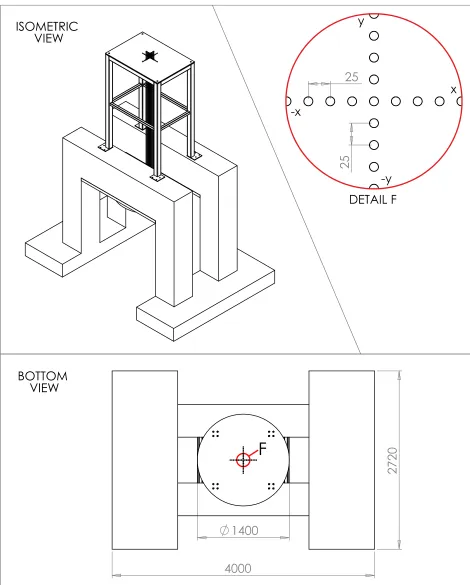
The experimental methodology used in this work has been reported in detail in [3] however brief details are presented here for the reader’s convenience. The testing rig consists of two reinforced concrete reaction frames, a rigid steel target plate, load cells and an array of HPBs. Figure 1 and Figure 2 give details of important dimensions and the overall layout of the rig. The rigid target plate is slung under the reaction frames bearing up against the 50 mm thick steel plates cast into both concrete frames. Each HPB passes through the rigid target plate in a slightly oversized hole, such that the loaded faces of the HPBs are flush with the face of the target plate. The HPBs are furnished with perimeter strain gauges mounted in pairs on opposite sides of the bar. This arrangement captures axial strain on the bar surface; while also automatically compensating for stresses due to bending, using the arrangement of the circuit. Blast events load the face of a HPB causing a stress pulse to travel down the bar straining the gauge material as it passes. This strain causes a change in voltage with time across the stain gauge arrangement. The data is recorded using an oscilloscope with sufficient voltage resolution and sampling rate to accurately capture the expected changes in voltage due to the mechanical strain of the gauges. In this way, for every discrete HPB location in the array, the pressure-time history on the loaded face of the bar can be calculated from the voltage-time history.
The spherical charges were supported under the centre of the target plate on a taut layer of thin glass-fibre fabric (density 25g/m2). This allowed accurate support and alignment of the charge with minimal difference to the “free air” event.
[image:3.612.67.546.443.598.2]Details of the arrangement of the tests are given in the table below.
Table 1: Charge details of the 6 tests
Test Number Explosive Material Charge Mass (grams)
Standoff to Charge Centre (mm)
Scaled Distance (m/kg1/3)
1 PE4 100 80 0.172
2 PE4 100 80 0.172
3 PE4 100 80 0.172
4 PE4 100 380 0.819
5 PE4 100 380 0.819
Results
[image:6.612.158.441.198.413.2] [image:6.612.163.439.462.675.2]The figures in this section aim to present the results of the experimental work using a range of perspectives; from spatially discrete pressure-time histories to total spatially integrated impulse. Figure 3 and Figure 4 are samples of the pressure-time histories recorded at each bar location for the 80 mm and 380 mm stand-off tests respectively. Figure 5 and Figure 6 are the pressure-time histories from figure 3 and Figure 4 integrated in time for each bar location showing the accumulation of specific impulse with time.
Figure 3: Example pressure-time history from test 3, -y radial ordinate
Figure 5: Example specific impulse history from test 3, -y radial ordinate
Figure 6: Example specific impulse history from test 4, -y radial ordinate
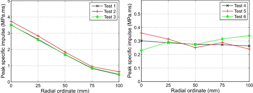
The peak pressure at each bar location has been determined and the values from bar locations with the same radial offset have been averaged together as shown in Figure 7; the same has been done for peak specific impulse as shown in Figure 8. Finally, Figure 9 shows the total impulse over a 100 mm radius; which has been determined for each test by interpolating, and integrating over 200 discrete radial bands of area.
pressure-time histories at any radial offset when comparing tests 1-3 to tests 4-6. Tests 1-3 show remarkably repeatable results for every radial offset of peak pressure with a maximum variation of 5.1% from the median over the 3 tests. Whilst tests 4-6 show a much larger percentage of variation at each radial offset with a maximum variation of 23.1% from the median over the 3 tests. Figure 10 illustrates an explanation which considers the physical phenomena taking place as the source of variation. Photo (a) shows a 100g sphere of PE4 just after the detonation products have begun to expand outwards and the surface of the expanding fireball is relatively uniform. Photo (d) shows this same event ~87µsec later where the detonation products have expanded ~75 times by volume; crucially though, it can be seen that large instabilities have developed on the surface of the detonation products which is also still driving the shock front which has not yet detached from the detonation products. It is clear that the turbulent growth of these instabilities, on the surface of the expanding detonation products, is the most likely source of increased variation in the discrete pressure-time histories for tests 4-6.
Figure 7: Average of peak pressures at each radial offset for tests 1-6
[image:8.612.83.525.472.634.2]Figure 9: Total impulse integrated over 100 mm radius for tests 1-6
[image:9.612.136.478.292.671.2]MODELLING WORK
Setup
[image:10.612.68.549.366.614.2]The explicit numerical code LS-DYNA [4] was used to perform an Arbitrary-Lagrangian-Eulerian (ALE) analyses of the two scenarios detailed in the experimental setup. Because the test arrangement was suitable, these analyses were completed in an axi-symmetric domain about the axis of the central HPB. The mesh was generated as a regular square grid large enough to avoid any complications as a result of material interaction with the model boundaries. Although a radial mesh symmetric about the charge centre and the central HPB axis was used to detonate and expand the explosive material to the point just before any interaction with the rigid boundary; at which point it was remapped onto the rectangular mesh. This was done to avoid the advection errors associated with material transportation at 45o to a square mesh. A mesh sensitivity analysis was performed. *BOUNDARY_SPC_NODE was used to simulate the rigid boundary of the target face in the experimental rig. Numerical information in the model was recorded for the locations of the experimental pressure bars using *DATABASE_TRACER. Figure 11 shows the basic layout of the ALE models. Table 2 gives details of the EOS and material models used in the analyses.[5]
Table 2: Material model and equation of state parameters for PE4 and air (SI units)
PE4 MAT_HIGH_EXPLOSIVE_BURN 0 1601 D 8193 PCJ
2.80E10
EOS_JWL
A
609.77E9
B
12.95E9
R1
4.50
R2
1.40 0.25
E0
9.0E9
Air MAT_NULL 0 1.225 EOS_LINEAR_POLYNOMIAL C0 0.0 C1 0.0 C2 0.0 C3 0.0 C4 0.4 C5 0.4 C6 0.0 E0
Figure 11: ALE model example schematic
Modelling results including comparison with experimental tests
Figure 12: Modelling vs experimental detonation products expansion and instabilities at ~12µsec & ~99 µsec
The pressure-time histories extracted from the model for the points corresponding to the experimental HPBs were applied to a numerical HPB in LS-DYNA and the resulting stress-time histories at 250 mm from the loaded face (the same as the experiments) of the bar were predicted It is general accepted that LS-DYNA numerical models are able to capture the effects of dispersion on the strain signals in the experimental HPBs. In this way the ALE modelling results can be post processed to allow for a more valid comparison with the experimental data; although both the raw outputs and the post processed outputs will be shown for completeness.
With respect to the development of instabilities in the detonation products with volumetric expansion Figure 12 provides a qualitative comparison on this phenomenon between the experimental HSV and the modelling results. It is worth noting that the modelling does not consider secondary combustion of the detonation products as a result of mixing with the air; which will certainly be a significant factor in the development and effects of this turbulent zone. It is likely that the instabilities seen in the modelling are Raleigh Taylor instabilities that are preserved by this modelling technique.
dispersion effects compared to the experimental average suggesting that the loading pulse in the experiments would have contained less high frequency content (sharp features) than the raw model results.
[image:13.612.69.545.307.428.2]Figure 13: Sample comparison of experimental measurements vs model results – test 2
Figure 14: Sample comparison of experimental measurements vs model results – test 4
The 4 subsequent tables provide a detailed comparison the average experimental results and the model results at each bar location for both peak pressure and peak specific impulse, considering both the raw model outputs and the post processed outputs. The model generally over-predicts pressure and impulse in all tests as seen in Tables 3 & 4.
Table 3: Comparison of numerical modelling results with averaged experimental results - 80 mm standoff, tests 1-3
Peak pressure (MPa)
Radial offset (mm)
Experimental
average (3 tests) Model Error
Model – post
processed Error
0 192 577 +200% 257 +33%
25 161 479 +197% 219 +36%
50 118 240 +103% 137 +16%
75 64 120 +87% 77 +20%
[image:13.612.65.550.551.709.2]Table 4: Comparison of numerical modelling results with averaged experimental results - 380 mm standoff, tests 4-6
Peak pressure (MPa)
Radial offset (mm)
Experimental
average (3 tests) Model Error
Model – post
processed Error
0 9.3 10.7 +15% 11.4 +22%
25 9.3 10.6 +14% 11.2 +20%
50 9.0 11.8 +31% 10.8 +20%
75 8.9 10.2 +15% 10.2 +15%
[image:14.612.73.547.501.655.2]100 8.2 9.3 +13% 9.7 +18%
Table 5: Comparison of numerical modelling results with averaged experimental results - 80 mm standoff, tests 1-3
Peak specific impulse (MPa.ms)
Radial offset (mm)
Experimental
average (3 tests) Model Error
Model – post
processed Error
0 3580 4170 +16% 3863 +8%
25 2682 3555 +33% 3283 +22%
50 1732 2310 +33% 2131 +23%
75 875 1380 +57% 1273 +45%
100 519 851 +63% 778 +50%
‘Table 6: Comparison of numerical modelling results with averaged experimental results - 380 mm standoff, tests 4-6
Peak specific impulse (MPa.ms)
Radial offset (mm)
Experimental
average (3 tests) Model Error
Model – post
processed Error
0 297 363 +22% 337 +13%
25 298 349 +17% 324 +9%
50 268 338 +26% 314 +17%
75 292 326 +12% 303 +4%
100 280 314 +12% 292 +4%
experimental results for a direct global comparison in Figure 15. This comparison shows that even though the magnitude of the specific impulse farther from the centre of the target may be low, an error can have significant effects on the total global impulse .
Figure 15: Total impulse integrated over 100 mm radius for tests 1-6 with modeling results and test averages
DISCUSSION/CONCLUSIONS
First, an interrogation of the HSV and the experimental measurements show that the relative magnitude of surface instabilities increases as the detonation products expand outward (Figure 10). Meaning that for any discrete point of interest on a rigid target the loading will be much more repeatable at smaller scaled distances. However, this criterion for repeatability will only apply to the range of scaled distances where detonation products are still affecting the shock front and a significant proportion of the loading is due to the reflection of the detonation products. That is, in the far field where targets are only affected by the detached shock front the repeatability of results will be higher than in this intermediate range. Repeatable results in the far field have been demonstrated in Rigby et al. [6]. Interestingly, the amount of test to test variation seen in the global impulse results is almost the same between tests 1-3 and 4-6; meaning that even though local pressure time histories may vary test to test, the global loading does not.
Finally, the results and comparisons presented in this paper show that repeatable experimental measurements of reflected pressure are possible at very small scaled distances, that turbulent instabilities grow with the expansion of the detonation products and that the JWL EOS for PE4 will significantly over predict pressure and impulse in the extreme near field. These finding are in keeping with the hypothesis that the JWL EOS releases the energy associated with secondary combustion upon detonation; rather than over a timescale as a result of mixing with free oxygen in the air.
REFERENCES
[1] J. Sanchidrian, R. Castedo, L. Lopez, P. Segarra, A. Santo., 2015, Determination of the JWL Constants for
ANFO and Emulsion Explosives from Cylinder Test Data, Universidad Politecnica, 12(2), 177-194
[2] C. Mader, 2008, Numerical Modeling of Explosives and Propellants, London, CRC Press
[3] S.E. Rigby, A. Tyas, S.D. Clarke, S.D. Fay, J. Reay, J.A. Warren, M. Gant, I. Elgy, 2015, Observations from
Preliminary Experiments on Spatial and Temporal Pressure Measurements from Near-Field Free Air Explosions, International Journal of Protective Structures, 6(2)
[4] J.O. Hallquist, 2006, LS-DYNA theory manual, Livermore Software Technology Corporation
[5] B.M. Dobratz, P.C. Crawford, 1985, LLNL explosives handbook, University of California
[6] S.E. Rigby, A. Tyas, T. Bennett, S.D. Fay, S.D Clarke, J.A. Warren, 2014, A Numerical Investigation of Blast