Iowa State University Patents
Iowa State University Research Foundation, Inc.
7-25-1978
Simultaneous reductive and oxidative
decomposition of calcium sulfate in the same
fluidized bed
Thomas D. Wheelock
Iowa State University, wheel@iastate.edu
Follow this and additional works at:
http://lib.dr.iastate.edu/patents
Part of the
Chemical Engineering Commons
This Patent is brought to you for free and open access by the Iowa State University Research Foundation, Inc. at Iowa State University Digital Repository. It has been accepted for inclusion in Iowa State University Patents by an authorized administrator of Iowa State University Digital Repository. For more information, please contactdigirep@iastate.edu.
Recommended Citation
Wheelock, Thomas D., "Simultaneous reductive and oxidative decomposition of calcium sulfate in the same fluidized bed" (1978).
Iowa State University Patents. 313.
Simultaneous reductive and oxidative decomposition of calcium sulfate in
the same fluidized bed
Abstract
Calcium sulfate is decomposed to CaO and SO
2by high temperature treatment in a fluidized bed wherein
reductive and oxidative conditions are simultaneously maintained. A highly reducing gas is formed in the
lower portion of the bed from partial combustion of the fuel in admixture with the primary fluidizing air. The
quantity of the primary fluidizing air is limited so that the reducing conditions in the lower zone converts the
CaSO
4to a mixture of CaO and CaS. Secondary air is introduced at a higher level in the bed to create an
oxidizing zone in the upper portion of the bed above the reducing zone capable of converting CaS to CaO.
The concurrent use of such reducing and oxidizing zones permits reducing conditions to be maintained which
favor a high rate of decomposition even though these conditions favor the formation of CaS as well as CaO.
The undesirable CaS, which would otherwise be discharged with the CaO product is eliminated by circulation
of the fluidized particles through the oxidizing zone. Further, the heat of the exothermic reactions is conserved
and utilized for promoting the endothermic reactions, both types of reactions occuring simultaneously while
the rapid fluidized circulation of solids maintains a relatively uniform temperature throughout the bed.
Keywords
Chemical and Biological Engineering
Disciplines
Chemical Engineering
United States Patent [191
Wheelock
4,102,989
Jul. 25, 1978
[11]
[45]
[54] SIMULTANEOUS REDUCTIVE AND
OXIDATIVE DECOMPOSITION OF CALCIUM SULFATE IN THE SAME FLUIDIZED BED
[75] Inventor: Thomas D. Wheelock, Ames, Iowa
[73] Assignee: Iowa State University Research
Foundation, Inc., Ames, Iowa
[21] Appl. No.: 686,727
[22] Filed:
May 17, 1976
Related U.S. Application Data [63] Continuation-in-part of Ser. No. 470,053, May 15,
1974, abandoned, which is a continuation-in-part of
Ser. No. 583,608, Jun. 4, 1975, abandoned.
[51] Int. Cl.2 ... .. C01B 17/50; COlB 13/14;
C04B 11/02
[52] US. Cl. ... .. 423/541 R; 423/168;
423/ 171; 423/638; 423/DIG. 16; 23/277 R
[58] Field of Search ... .. 423/168, 170, 171, 172,
423/539, 541, 542, 530, 555, 635, 638; 23/277 R [56] References Cited
U.S. PATENT DOCUMENTS
2,232,099 2/1941 deJahn . . . . . . .. 423/168
2,733,137 l/1956 Swaine et a1. . . . . . . .. 423/542
2,825,628 3/1958 Johannsen et al. . 423/542
2,993,778 7/1961 Johannsen et a1. . 423/542
3,198,602 8/1963 Wittmann ... .. 423/542
3,260,035 7/1966 Wheelock et- a1. ... .. 423/170
3,582,276 6/1971 Campbell et al. 423/539
3,607,045 9/1971 Wheelock ... .. 423/541
3,729,551 4/1973 Gorin ... .. 423/638
FOREIGN PATENT DOCUMENTS
590,975 1/ 1960 United Kingdom ... .. 423/541 643,479 9/ 1950 United Kingdom ... .. 423/541
OTHER PUBLICATIONS
Martin et a1., “Decomposition of Gypsum in a Fluidized
e- ‘a, IIIB
FLUIDllED BID REACYO ‘
OIIBIZIIIG ZONE
Full. 645 AND PRIIIIY III
Bed Reactor,” U.S. Bureau of Mines, Report of Investi
gations, 6286, 1963, 423, 541.
Environmental Protection Technology Series EPA
65012-74-001, Jan. 74 entitled, “A Regenerative Lime
stone Process for Fluidized Bed Coal Combustion and
Resulfurization.”
Primary Examiner-O. R. Vertiz Assistant Examiner-Gary P. Straub
Attorney, Agent, or Firm—Tilton, Fallon, Lungmus &
Chestnut
[57]
ABSTRACT
Calcium sulfate is decomposed to CaO and S02 by high
temperature treatment in a ?uidized bed wherein reduc tive and oxidative conditions are simultaneously main tained. A highly reducing gas is formed in the lower
portion of the bed from partial combustion of the fuel in admixture with the primary ?uidizing air. The quantity
of the primary ?uidizing air is limited so that the reduc ing conditions in the lower zone converts the CaSO4 to a mixture of CaO and CaS. Secondary air is introduced at a higher level in the bed to create an oxidizing zone
in the upper portion of the bed above the reducing zone
capable of converting CaS to CaO. The concurrent use
of such reducing and oxidizing zones permits reducing
conditions to be maintained which favor a high rate of
decomposition even though these conditions favor the
formation of CaS as well as CaO. The undesirable CaS,
which would otherwise be discharged with the CaO product is eliminated by circulation of the fluidized particles through the oxidizing zone. Further, the heat
of the exothermic reactions is conserved and utilized for
promoting the endothermic reactions, both types of
reactions occuring simultaneously while the rapid ?uid
ized circulation of solids maintains a relatively uniform
temperature throughout the bed.
8 Claims, 3 Drawing Figures
U. S. Patent
July 25, 1978
Sheet 1 of 2
ca 804 FEED so2 OFF-GAS
1
1
2e
7/’ z 1/ II n 1/ u 1/ II 1/ 1,
FIG.\
,1, f1
24
,
’ GAS ;
M_ - 23 ;
CYCLONE
I
I/SEPARATOR
10/’:
1
¢
:
1
E
z
5
g./ ll
FLUIDIZED ’ 25/ ' ¢
BED azAcro?’
lousT
‘
1 l2- ’
, GAS GAS 9 21
1.1 i- - '
2
.4
OXIDIZING
ZONE
2
’4
:C60 PRODUCT
I
22/7
4
2 '
4
7
¢
1
1
21-;
Z
nsoucme;
}
ZONE
4
¢
l5?’
1 4
,
4 4 §
4
FUELGAS A'ND
’ 1
|_a_
§ 4
PRIMARY AIR
'6
V
‘7 l/ 1/ 1/ n 1/‘ 11/1, I/ a II I?
seconomv - '
AIR
[9 20
U. S. Patent
July 25, 1978
Sheet2 of2
4,102,989
‘
C0804 FEED oFF-cAs _
FLUIDIZED
GAS
BED REACTOR -cYcL°NE SEPARATOR
‘ousr
FIG. 2
\ ‘FFIAYFI‘I-ITT
\\\F|LU|D|ZED
oxmzmc \“ "sawed/v”
cm
ZONES _ PRODUCT
nsoucmc zone 1'
SECONDARY AIR r __""
PRIMARY AIR FUEL on
Cu. 804 FEED ' S02 OFF-GAS
.‘l - 7-26
/////1 ///////
¢F
/
¢
23
2
‘04/
Cyclone
F|G.3
; .44
/
separator
/
1
j
/._||
/ 25 /'
Fluldlzed sad;
;
ROGO'OI‘ I‘;
/
/ /
/
4
lOc’;
‘p
/
Fluid ized
f
28
/
Bed
,
oxidizing
/
Zone
22
CaO Prod ucf
A
Reducing
L\ r
20
Zone
\
,
20‘ \
’
[On-r I 1
l9 .
i
Z
Secondary Air h.
rl7~ II?
4,102,989
1
SIMULTANEOUS REDUCI‘IVE AND OXIDATIVE DECOMPOSITION OF CALCIUM SULFATE IN
THE SAME FLUIDIZED BED
CROSS-REFERENCES
This application is a continuation-in-part of my co
pending application, Ser. No. 470,053, ?led May 15,
1974, now abandoned and is also a continuation-in-part
of my related co-pending application, Ser. No. 583,608, ?led June 4, 1975, now abandoned.
BACKGROUND AND SUMMARY
In Wheelock and Boylan U.S. Pat. No. 3,087,790
there is disclosed a process for reductive decomposition of calcium sulfate which can produce a calcium oxide
product substantially free of calcium sul?de together
with recoverable sulfur dioxide. To minimize contami
nation of the CaO product with CaS, it is necessary to
control the temperature of the reaction within narrow limits, namely within the range from 2150° to 2250“ F.,
and to control the quantity of reducing gas (C0 and Hz)
to about 1 to 7% of the gaseous atmosphere, the C02 in the gaseous atmosphere being present in an amount greater than the combined amounts of the reducing gas and S02. When the process is operated on a continuous basis, therefore, the rate of the reduction reaction is limited, which in turn limits the through-put rate of the calcium sulfate. As disclosed in the later Wheelock and
Boylan U.S. Pat. No. 3,607,045, the reductive decompo
sition may be carried out in a single ?uidized bed with
the reducing gas produced in situ by partial combustion
of a hydrocarbon gas within the ?uidized bed. This
arrangement permits the air and fuel gas to be preheated by indirect heat exchange contact with the off-gas from
the reactor, and the calcium sulfate feed can also be
preheated by direct heat exchange contact with the
off-gas. Substantial fuel and heat economies result, but it is sill necessary to carefully control the temperature and the CO and H2 content of the reducing gas. U.S. Pat. No. 3,607,045 speci?es the use of an amount of air pro viding from about 1.3 to 1.8 moles of 02 per mole of C in the fuel gas. Reaction rates and through-put rates are therefore limited.
The equations representing the reactions involved in reductive decomposition of CaSO4 by CO and H2 are:
caso, + co _> Ca0 + c0z + so,(1)
caso, + H2» Ca0 + [1,0 + so,(2)
caso4 + 4 co _> CaS + 4C02 (3)
C350, + 4 H2-> CaS + 4n,o (4)
In general, the desired product reactions of equations
(1) and (2) are preferentially favored over reactions (3)
and (4) by mildly reducing conditions. The undesired
reactions of equations (3) and (4) are promoted by more
highly reducing conditions. However, it is apparent that
the rate of all of the reactions can be increased by in
creasing the concentration of the reducing gas (CO
and/or Hz), the driving force of the decomposition
reactions being generally proportional to the concentra tion of the reducing agents. But if the gas phase is strongly reducing, calcium sul?de will be produced in objectional amounts and if the gas phase is weakly re ducing, the rate of desulfurization will be undesirably
slow.
From the standpoint of minimizing investment capital
in relation to production capacity, it would be desirable
10
15
20
30
35
45
50
55
60
65
2
to use as large concentrations of the reducing agents as
possible. On the other hand, a high quality lime (CaO)
product should be as free as possible from CaS. Further,
where the product is incompletely desulfurized, either
because of the presence of CaSO4 or CaS, the recover
able SOZ is reduced. The improved process of the pres
ent invention provides a greatly improved means for
accomplishing these con?icting objectives.
A related problem is a tendency of the calcium sulfate
feed to sinter during the high temperature treatment
required for the reductive conversion. With natural
calcium sulfate ores, such as gypsum and anhydrite, which are relatively pure gypsum or anhydrite, sinter
ing can be largely avoided by maintaining temperatures
below 2250“ F. However, calcium sulfate wastes from
various manufacturing operations and industrial pollu
tion control systems have a greater tendency to sinter
because of the presence of other ingredients which reduce the sintering temperature of calcium sulfate. Consequently, objectionable sintering may occur within
the temperature range of 2150° to 2250° F ., which here
tofore has been believed to be the optimum temperature
for converting calcium sulfate to calcium oxide with minimized formation of calcium sul?de.
Prior to the present invention, the state of the art indicated that temperatures below 2150° F. would cause
incomplete desulfurization and formation of calcium
sul?de. With the improved process of the present inven tion, however, lower temperatures than 2150° F. can be used without objectionable contamination of the lime
product with CaS. Further, the lower temperatures permit the conversion of calcium sulfate wastes which otherwise would be subject to sintering.
Calcium sul?de can be removed from calcium oxide
by a high temperature oxidizing roast. For example, as
disclosed in Campbell et a1 U.S. Pat. No. 3,582,276, after calcium sulfate is treated with a reducing gas, calcium sul?de in admixture with calcium oxide can be treated with air or other oxygen-containing gas to convert the CaS to CaO and S02. The equation can be represented
as follows:
CaS + 3/2 o,_> Ca0 + so2 (5)
However, calcium sul?de can oxidize to calcium
sulfate by the following reaction:
CaS + 2 02 -> caso4 (6)
While the reaction of equation 6 eliminates the undesir able CaS, the reformation of CaSO4 results in incom
plete desulfurization of the product with decreased
production of the S02 by-product.
In the early l950’s, experiments relating to the reduc
tive decomposition of calcium sulfate were conducted by Walter M. Bollen, as a graduate student in the De
partment of Chemical Engineering, at Iowa State Col
lege, Ames, Iowa. The results of these studies are re
ported in Bollen’s Ph.D. Thesis, “Thermal Decomposi
tion of Calcium Sulfate” (1954). These experiments
were carried out in a batch-type ?uidized bed reactor, which was supplied with the products of combustion of burning natural gas and air in a combustion chamber
located outside of the ?uidized bed. Bollen experi
mented with oxidation treatments to remove CaS from the CaO product, as reported in his above cited 1954
4,102,989
3
for reducing Gas in a CaO product. A similar post treatment procedure is disclosed in the US. Patent of Campbell et al, No. 3,582,276. More speci?cally, at the conclusion of the reductive decomposition, Bollen ei ther increased the ratio of air to gas much above the theoretical amount for complete combustion of the fuel
gas, or the fuel gas was turned off entirely and only air
was supplied to the ?uidized bed. In either case, the result was a subsequent or last stage oxidizing treatment of the batch of CaO product to remove contaminating CaS.
Bollen also concluded that the CaS content of the
CaO product could be reduced by decomposing the
calcium sulfate at his recommended temperature of about 2350“ F. with an air-gas ratio representing sub
stantially 100% stoichiometric air for complete combus
tion as determined without reference to the CaSO4
decomposition. Theoretically under this condition, the ?uidizing preformed combustion gas entering the bed should contain no reducing gases (CO and/or H2).
However, Bollen’s data appears to indicate that under the condition assumed to be 100% stoichiometric air for
complete precombustion, traces of both 02 and CO
were present; analysis of the combustion gas as intro duced showing amounts of carbon monoxide and oxy gen, such as 0.5% CO and 0.7% 02. At 95% precom bustion stoichiometric air, the gas analysis showed no oxygen and more carbon monoxide (viz. 2.6% CO;
0.0% 02). However, at 105% precombustion stoichio
metric air, the gas analysis showed no carbon monoxide and more oxygen (viz. 0.0% CO; 1.4% 02). This data is dif?cult to interpret.
Bollen hypothesized that at 100% precombustion
stoichiometric air, alternating reducing and oxidizing
conditions may have been obtained in the reactor. His
observations overlook the 02 formed by CaSO4 decom
position, which would provide a total excess of 02. Moreover, since the driving force of the reaction of carbon monoxide with oxygen to produce carbon diox
ide is exceedingly large at the temperatures employed in Bollen’s reactor, if both reducing and oxidizing condi
tions occurred, a more likely explanation is that the relative proportions of fuel gas and air ?uctuated. With
slight variations from 100% theoretical precombustion
stoichiometric air over gas sampling intervals of several
minutes, the collected gas sample might possibly con
tain small amounts of both carbon monoxide and oxy gen, the sample, in effect, being an average of the slightly varying gas conditions in the reactor over a
?nite period of time. Whatever the theoretical explana
tion, it is apparent that Bollen’s optimum conditions are not feasible for commercial decomposition of calcium sulfate. Even assuming that both carbon monoxide and oxygen can be present when the reactor is supplied with a gas-air combustion gases the amount of CO (and/or H2) would be too small for effective reductive conver sion of calcium sulfate to calcium oxide; that is, the reaction rate would be too slow for commercial use. Further, desulfurization would be incomplete in reason able reaction times, and it would be expected that the
by-product S02 would be produced in low yields at
dilutions, which would make recovery impractical on a commercial basis.
The US. Patents of Robinson et a1, Nos. 3,717,700 and 3,763,830 related to a process and apparatus for
burning sulfur-containing fuels such as powdered coal. A ?uidized bed of lime (CaO) is utilized to capture S02 released from the burning coal. The lime is thereby
15
20
25
40
45
50
55
65
4
converted to calcium sulfate, which is decomposed to lime for process reuse in a separate fluidized bed regen erator. In the lime regenerator, air is introduced into the bottom of the bed as the ?uidizing gas. The powdered
coal is pneumatically conveyed with air into the lower portion of the regenerator. The powdered coal provides
the fuel for the regeneration. In operation, the air ?ow is controlled to produce an overall excess of oxygen, the
off-gas from the regenerator containing from about 0.5
to 2.5% oxygen.
By the improved process of the present invention,
calcium sulfate can be decomposed at a greatly acceler~
ated rate under highly reducing conditions, without paying the price of objectionable calcium sul?de con
tamination of the ?nal lime (CaO) product as dis
charged from the reactor. In the reductive decomposi
tion reaction which occur in the lower portion of the bed where partial, limited in situ combustion of the fuel
also takes place, the calcium sulfate is subjected to highly effective rapid rate reducing conditions. At the same time, although such strong reducing conditions favor the production of the undesirable calcium sul?de, the oxidizing conditions maintained in the upper portion of the bed expose the rapidly circulating particles to
conditions converting CaS to CaO, while any reformed
CaSO4 is continuously circulated through the reducing
zone. More complete desulfurization is thereby
achieved, and the resulting product can be substantially
free of both calcium sulfate and calcium sul?de. By
having the oxidizing zone above the reducing zone, the off-gas by-product can contain recoverable S02 sub
stantially free of sulfur vapor or reduced sulfur gases, such as H28, carbonyl sul?de, etc.
From the standpoint of heat conservation, the heat generated by the exothermic oxidation reactions of equations (5) and (6), as they occur in the oxidation
zone, can contribute to the total heat required for the
endothermic decomposition reactions of equations (1)
and (2). In the reducing zone, reactions (3) and (4) are
exothermic. However, the process does not depend on these reactions to supply the energy for reactions (1) and (2). Because of the continuous circulation of mate rial within the ?uidized bed reactor, the occurrence of
exothermic reactions in another portion of the bed, does
not lead to undue ?uctuations in the bed temperature.
On the contrary, the temperature throughout the ?uid
ized bed can be controlled to relatively stable tempera ture, which favors the desired reactions and avoids
sintering.
THE DRAWINGS
The accompanying drawings comprise diagrammatic
illustrations of three embodiments of the improved pro cess of the present invention,
FIGS. 1 to 3 being cross-sectional elevational view of ?uidized bed reactors equipped with means for concur
rently maintaining oxidizing and reducing zones within
the same ?uidized bed.
In the following detailed description, the illustrations
of FIGS. 1 to 3 will be explained.
DETAILED DESCRIPTION
Since the present invention represents an improve ment on the processes described in prior US. Pat. Nos.
3,087,790 and 3,607,045, the disclosures of these patents
4,102,989
5
duction and oxidation reactions can be simultaneously carried out in the same bed.
In practicing the present invention, the feed to the
?uidized bed reactor is preferably a calcium sulfate
anhydrite mineral. The principal component of such
minerals is anhydrous calcium sulfate, although this is
usually present in admixture with a minor proportion of
gypsum, which is hydrated calcium sulfate (CaSO4.2
H2O). A gypsum mineral ore can also be utilized, or a
gypsum mineral ore mixed with an anhydrite mineral.
Industrial waste materials composed mainly of calcium
sulfate can also be utilized.
As used herein, unless otherwise designated, the term
“calcium sulfate” is intended to refer to both anhydrous
and hydrated calcium sulfate. Unless the calcium sulfate
is already in a state of ?ne subdivision, it is prepared for
use in the process by crushing, grinding, and screening to produce a finely-divided feed of relatively uniform
mesh size, such as -6 to +65 mesh (Tyler Standard
Screen).
In one embodiment, the feed to the reactor is the
sulfated lime produced by utilizing lime to capture the
sulfur dioxide produced in the ?uidized bed combustion
of sulfur-containing coals. As indicated above, such
fluidized bed combustion of sulfur-containing coal is
described in US. Pat. Nos. 3,717,700 and 3,763,830. The
feed to the regenerator reactor will therefore consist primarily of a mixture of anhydrous calcium sulfate and unreacted calcium oxide in a ?ne state of subdivision. Magnesium oxide may also be present if dolomitic lime has been used in the ?uidized bed combustion.
The ?nely divided calcium sulfate feed is supplied to
a ?uidized bed reactor, providing a single reaction bed
within which the solid particles freely circulate. Where the desired capacity cannot be provided by a single
reactor, a plurality of separate ?uidized bed reactors can be used, each reactor being supplied with the cal cium sulfate feed and each reactor producing the ?nal
calcium oxide product.
It will be understood that the reactor beds will be designed in accordance with well-known principles so
that the bed of fmely-divided calcium sulfate is capable
of being ?uidized by a ?uidizing gas mixture. The fuel
for in situ combustion produces the reducing gas (CO
and/or H2). Carbonaceous fuels usable for such pur pose, as is known in the art, include gaseous and liquid
hydrocarbon fuels (viz. natural gas or petroleum oil) and solid carbon fuels (viz. powdered coal). The fuel when partially burned should produce a reducing gas containing at least CO and preferably both CO and H2.
Hydrogen-containing carbonaceous fuels are therefore preferred. Effective control of the reducing zone condi
tions can be readily achieved by using a hydrocarbon
gas, such as natural gas. However, a liquid hydrocarbon fuel can be used. In either case, precombustion is not
desirable. Consequently, where the extent of preheating
of a hydrocarbon gas or the air is such that on mixing, precombustion may occur outside of the reactor, the air and gas are preferably separately supplied on the reduc ing zone of the reactor. The hydrocarbon gas or liquid fuel and air mix and burn on being introduced to the
?uidized bed, forming in situ a reducing gas containing CO and H; as the reducing agents. Since coal contains
volatiles, it will also form both H2 and CO on partial combustion. The coal may also be supplemented with a
hydrocarbon gas. A preferred procedure for using high
volatile coal as the fuel will be describedsubsequently.
20
45
50
6
In accordance with the present invention, the air
?ows are carefully controlled. The proportion of air to fuel introduced into the lower reducing zone portions
should be such that substantially less 02 is available in the reducing zone for complete combustion of the fuel. According to equations (1) to (4), this results in the
conversion of CaSO4 to a mixture of CaO and CaS. The air fed to the lower reducing zones is referred to herein as the “primary” air, while the air fed to the upper oxidizing zones is called the “secondary” air. For
hydrocarbon fuels, such as natural gas or petroleum oil, the proportion of the primary ?uidizing air to the fuel
fed to the reducing zone portion can range from about 20 to 90%, such as 30 to 70%, of the stoichiometric
quantity of air (on a 02 basis) required for complete
combustion of the fuel to CO2 and H20. Preferably,
however, at least 40% of stoichiometric air is used for the initial admixture with the fuel. In general, the most
desirable operating range in the lower reducing zones
for hydrocarbon fuels is believed to be within the range
from about 40 to 65% of the air required for complete combustion of the fuel to CO2 and H20.
To maintain an oxidizing zone in the upper portions of the bed capable of converting CaS to CaO, excess
oxygen is sustained therein by feeding secondary air to
the oxidizing zone of the ?uidized bed at a controlled
rate. At the point of introduction of the air, strongly
oxidizing conditions can be obtained, and at least mildly oxidizing conditions can be maintained over a zonepof suf?cient size to oxidize calcium sul?de particles as they circulate through the upper portion of the ?uidized bed. When the oxidation results in the reformation of cal
cium sulfate particles, such particles will be recirculated
into and through the reducing zone, thereby decompos
ing and reformed calcium sulfate to the desired calcium oxide. With gas or liquid hydrocaron fuels, the quantity
of secondary air can range from as little as 10% up to as much as 60% of the total air (primary and secondary). The secondary or oxidizing air ?ow will usually be a
lesser volume than the primary air ?ow. For example,
the secondary air may range from 15 to 40% of the total air introduced.
In operating the process to sustain ?uidization it is necessary to remove the ?uidizing gas from the top of
the bed, and for convenience of operation it is prefera
ble to remove the lime product from the upper portion of the bed. This arrangement works out well with the reducing zone or zones, in the lower portion of the bed, and the oxidizing zone or zones above the reducing zones, in accordance with present invention. The reac
tion products are thus discharged from the oxidizing
zone as they leave the reactor, which increases the likelihood that they will be in an oxidized state when > they exit. Moreover, the off-gas can contain S02 sub
55
60
65
stantially free of S, HZS, etc.
The primary ?uidizing gas is the air, or the mixture of
air and fuel gas, introduced into the bottom of the reac
tor. This ?uidizing gas ?ows upwardly through the bed,
and is removed from the gas space above the bed. The CaO product is preferably removed from an upper por tion of the bed beneath which air is fed to the oxidizing zone. The upper boundaries of the oxidizing zone do not need to be precisely established or maintained.
However, the product is preferably removed from an upper portion of the bed in which essentially oxidizing
conditions exist. It is convenient to remove the CaO
product from the uppermost portion of the bed. The
4,102,989
7
with respect to reducing potential, containing essen
tially no CO or H2. Some excess oxygen, however, may be present, such as 0.5 to 2% O2 in the off-gas on a molar basis.
The decomposition of calcium sulfate produces oxy gen which is available to combine with the carbon and
hydrogen of the fuel, one-half mole of oxygen (02)
being produced for each mole of calcium sulfate decom
posed. In general, for optimum thermal and material
efficiencies, the total amount of air supplied to the reac
tor, including the air supplied to both the reducing and
oxidizing zones thereof, should be equal to the stoichio
metric quantity of air (on an 02 basis) required for com plete combustion of the fuel to CO2 and H20 less the
amount of air equivalent (O2) supplied by the decompo
sition of calcium sulfate. Although some additional air
above this optimum value, as indicated above, may be
supplied to insure complete combustion of the fuel and
to provide a slightly oxidizing off-gas, large excesses of
air result in corresponding losses in thermal and mate
rial ef?ciencies. The off-gas can be analyzed periodi cally or continuously in monitoring the process. Advan
tageously, the off-gas is substantially free of CO, H2,
and unburned fuel, containing N2, 00;, H20, 80;, and
a small percent of 02.
Since the total quantities of both fuel and air required
for optimum thermal and material efficiencies can be
determined by applying well-known material and en
ergy balance calculations, no claim of novelty or inven
tion is made with respect thereto. For any given fuel,
CaSO, feed rate, and bed temperature, the optimized
total air required for the fuel combustion can also be
determined experimentally. This has been done previ
ously. The bene?ts of the present invention are
achieved by splitting the total ?ow of air to the reactor into primary and secondary flows which are fed respec
tively to reducing and oxidizing zones, as described above, and which are apportioned relative to each other
to maintain the oxidizing and reducing conditions.
' The average temperatures to be maintained in the ?uidized bed can be in accordance with the temperature
speci?ed in prior US. Pat. Nos. 3,087,790 and 3,607,045, that is, within the range from 2150“ to 2250°
F. Temperatures above 2250° F. are not desirable. How ever, one of the advantages of the process improvement
of the present invention is that lower temperatures can
be employed than 2150‘ F. For example, where the use of lower temperatures is desirable, as where the feed has a tendency to sinter at temperatures in the range of 2l50° to 2250° F., the temperature can be reduced
below 2150° F. Consequently, where a sintering prob
lem is encountered with the feed, it may be desirable to operate at a temperature in the range of about 1950" to
2125° F. Such lower temperatures will also reduce the
quantity of fuel required. Therefore, the temperature
condition of the reactor bed when employing the fea
ture of the present invention is from about 1950° to 2250'’ F.
Referring to the diagrammatic view of FIG. 1, the
?uidized bed reactor 10 comprises a vessel having a
heat-insulating jacket 11. In the lower portion of the
reactor there is provided a ?uidized bed designated generally by the number 12 and in the upper portion a gas space 13. As shown, the G180, feed is supplied through the top of the reactor by means of a feed pipe or conduit 14, which extends downwardly to approxi mately the top of the bed 12. The ?uidized bed 12 is supported on a gas distributor plate 15, which is pro
20
25
30
35
40
45
55
60
65
8
vided with a plurality of upwardly extending inlet pas
sages 16. These passages are distributed in all directions across the plate 15, and are arranged to provide for uniformity of gas inlet ?ow across the bed. As shown, a common fuel gas and primary air inlet 17 is provided in the lower portion of the reactor communicating with the gas space 18 below the distributor 15.
As previously indicated, where the fuel gas, such as natural gas, and/or combustion air are preheated to temperatures which on mixing will tend to produce
immediate combustion, separate inlets may be provided for the fuel gas and primary air. In the arrangement
shown, these separate inlets can communicate with the vapor space 18, or the primary air alone can be supplied
through the inlet 17, and pipe means provided for sup plying gas to nozzles or jets supported in the plate 15. With any of these arrangements, the fuel gas and pri
mary air will enter the lower portion of the ?uidized
bed 12 together, causing the fuel to be partially burned
in the lower portion of the bed, and thereby producing
reducing quantities of carbon monoxide and hydrogen.
Additional air, referred to in FIG. 1 as secondary air is also supplied to a portion of the bed location at a
higher level than that at which the fuel gas and primary
air are introduced. As shown, the secondary air is intro
duced through a manifold pipe 19 which communicates with the distributor pipes 20 that extend upwardly
through plate 15 to an intermediate level within the ?uidized bed 12. With this arrangement, as indicated by the labels on FIG. 1, a reducing zone 21 is provided in
the lower portion of the bed, and an oxidizing zone 22
in a portion of the bed above the reducing zone.
Strongly reducing conditions can thereby be main tained in the lower portion of bed 12, while oxidizing
conditions are maintained in an upper portion thereof.
Immediately adjacent to the outlets from pipes 20, a highly oxidizing condition will be present. As the re ducing gases ?ow upwardly from the lower zone 21, and mix with the air introduced through pipes 20, the
carbon monoxide and hydrogen, as well as any residual hydrocarbon, will be burned. The amount of CO and
H2 in relation to the amount of 02 will gradually reduce.
Thus, an oxidizing zone can be maintained above the reducing zone, while at the same time, the off-gas leav
ing the top of the bed 12 can be essentially neutral, but
preferably is slightly oxidizing. Typically, the off-gas
will be composed essentially of N2, H2O, CO2 and S02,
and will contain a small amount of O2 (vix. 0.5-2.0 mole
%), while being essentially free of CO, H2, unburned
fuel (CH4, C2H6, etc.), and reduced forms of sulfur (S,
HZS, 6110.).
Since fine solids (dust) may be entrained in the gas leaving the bed, the gas may be passed through a solids
separator, such as a cyclone separator. As shown, a
cyclone separator 23 is located within the upper portion of gas space 13. The off-gas enters the separator through a side inlet 24. The separated dust is returned to
the ?uidized bed through a downwardly extending pipe
or conduit 25. The puri?ed gas, containing the recover
able SOZ is removed through a top outlet 26 which extends through the top wall of reactor 10. It will be understood that these features of equipment design may
be varied, such as, for example, by locating the cyclone
separator outside of the reactor.
Means are also provided for removing the CaO prod
uct from the upper portion of bed 12. As shown, a dis
4,102,989
9
tioned at the top of the bed 12, and serves to control the
upper level of the bed. The lime product is discharged through a pipe or conduit 28 extending downwardly
and outwardly from outlet opening 27 through the adja
cent side wall of the reactor.
The present invention may be better understood, both theoretically and in relation to practical commercial
embodiments, by considering the following examples.
EXAMPLE I
Tests were conducted using a bench-scale reactor
adapted to provide separate reducing and oxidizing
zones in accordance with the principles of the present invention.
The reactor was constructed of refractory materials for the most part and had a steel shell to prevent leakage of gases to the atmosphere. The outer shell was insu lated to reduce heat losses. When the reactor was in use,
it contained ?uidized, reacting solids up to the over?ow pipe which passed through the side of the reactor. Pri
mary air and natural gas were admitted through the bed support plate at the bottom of the reactor and second ary air through a ceramic tube which passed through the top of the reactor and was immersed in the ?uidized bed, extending downwardly to an intermediate level.
The bed support plate was covered by several layers of
alumina pellets for protection. Finely divided solids
were pneumatically conveyed into the reactor by the secondary air and reacted solids were removed through the over?ow pipe. Gases were removed through an exhaust port near the top of the reactor. The ?uidized bed temperature was determined with a chromel-alumel thermocouple placed in a mullite ceramic protection
tube inserted in the bed.
Two reaction zones were achieved by limiting the ratio of primary air to natural gas so that the lower part of the ?uidized bed was reducing in character and by introducing sufficient secondary air so that the upper part of the bed was oxidizing. Since the bench-scale reactor was not insulated suf?ciently to avoid relatively
large heat losses, either the primary or secondary air or
both had to be enriched with oxygen to achieve the
necessary operating temperatures. Such enrichment
would not be necessary on an industrial scale where the reactor could be insulated more effectively.
Compressed air, oxygen and natural gas were me
tered individually and mixed before reaching the gas
distributor at the bottom of the reactor. Additional compressed air and sometimes oxygen were metered
and mixed before being supplied as secondary air.
Finely divided solids were introduced at a controlled rate into the secondary air by a screw feeder and were
then transported by the air into the reactor. The gas
which issued from the top of the reactor was passed through cyclone separators and a bag ?lter to remove entrained solids and then through a condenser to con
dense water vapor. After separating the condensate, the
gas was conducted to an ejector which vented to the
atmosphere. The ejector was operated so that the gas
pressure in the reactor was only slightly greater than
atmospheric pressure. Samples of the product gas were
collected from a point between the reactor and cyclone separator and were analyzed with a gas chromatograph. Two natural ores of calcium sulfate which had been
crushed and screened to — 14 +35 mesh size were used
for the test operation of the reactor. One of these ores were predominantly gypsum (G) whereas the other was
10
20
25
35
45
50
55
60
65
10
predominantly anhydrite (A). The approximate chemi
cal composition of the ores were:
Gypsum Anhydrite Ore Constituents (Wt. % in Ore)
Anhydrite (CaSO4) —- 73.4
Gypsum (CaSO4. ZHZO) 94.7 24.4
Calcium and magnesium
carbonates 1.6 0.6
Silica (SiO2) 3.3 —
Sodium Chloride (NaCl) 0.3 —
Other constituents 0.1 1.6
100.0 100.0
Natural gas used for the heat operation had the fol
lowing average composition as determined with a gas
chromatograph:
Constituents Mole %
Methane (CH4) 88.2 Ethane (C2H6) 4.8
> Nitrogen (NZ) 7.0
100.0
Combustion tests were carried out to determine the effect of the air to natural gas ratio on the composition
of the combustion products. These tests were made by
burning natural gas and air mixtures in a two-inch diam eter ceramic tube containing an inert alumina packing. Combustion took place at atmospheric pressure and at temperatures in excess of 2000° F. The combustion products were analyzed with a gas chromatograph after the water had been condensed out. Since the chromato
graph was incapable of separating oxygen and argon,
these two components, which are both present in air, were determined together. The results showed that with an air to natural gas ratio of 10, an essentially neutral mixture of combustion products was obtained;
lower ratios provided reducing gas mixtures containing
free hydrogen and carbon monoxide and higher ratios
provided oxidizing mixtures containing free oxygen.
Moreover, as the ratio decreased below 10, the concen
trations of reducing agents increased.
A number of test runs were made in which the two zone reactor was used to continuously decompose natu ral ores of calcium sulfate. During the tests, the depth of the ?uidized bed was maintained at approximately 9 to 10 inches in the 4.75-inch I.D. reactor. The feed, com prising the gypsum or anhydrite, was sized to between - l4 and +35 mesh (Tyler Standard Screen). Each of
the runs was continued for several hours so as to
achieve essentially steady-state conditions in which the solids feed and over?ow rates, gas ?ow rates, product
gas composition, and ?uidized bed temperature were nearly constant. Various system parameters were
changed from run to run so as to determine their effects
on desulfurization of the solids and product gas compo sition.
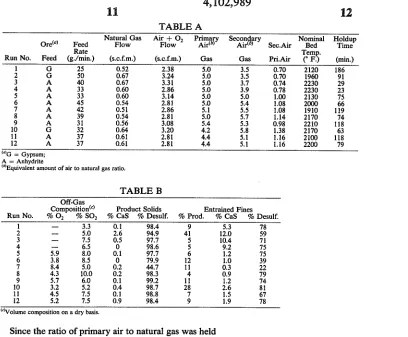
Operating conditions used for these runs are pres ented below in Table A, and the results obtained are
presented in Table B. Only key items are included. Thus, only the concentrations of oxygen and sulfur dioxide in the reactor off-gas are given and product solids are characterized only by percent desulfurization
and calcium sul?de content. The ratio of the total ?ow of air to gas is not tabulated, since it is the sum of pri
4,102,989
11
12
TABLE A
Natural Gas Air + 02 Primary Secon ary Nominal Holdup
Ore“) Feed Flow Flow Airlb) Air< ) Sec.Air Bed Time
Rate Tem .
Run No. Feed (g./min.) (s.c.f.m.) (s.c.f.m.) Gas Gas Pri.Air (° F. (min)
1 G 25 0.52 2.38 5.0 3.5 0.70 2120 186
2 G 50 0.67 3.24 5.0 3.5 0.70 1960 91
3 A 40 0.67 3.31 5.0 3.7 0.74 2230 29
4 A 33 0.60 2.86 5.0 3.9 0.78 2230 23
5 A 33 0.60 3.14 5.0 5.0 1.00 2130 75
6 A 45 0.54 2.81 5.0 5.4 1.08 2000 66
7 A 42 0.51 2.86 5.1 5.5 1.08 1910 119
8 A 39 0.54 2.81 5.0 5.7 1.14 2170 74
9 A 31 0.56 3.08 5.4 5.3 0.98 2210 118
10 G 32 0.64 3.20 4.2 5.8 1.38 2170 63
11 A 37 0.61 2.81 4.4 5.1 1.16 2100 118
12 A 37 0.61 2.81 4.4 5.1 1.16 2200 79
mG = Gypsum;
A = Anhydrite
(“Equivalent amount of air to natural gas ratio.
TABLE B
Off-Gas
Composition“) Product Solids Entrained Fines
Run No. % O2 % S02 % CaS % Desulf. % Prod. % CaS % Desulf.
1 — 3.3 0.1 98.4 9 5.3 78
2 -- 5.0 2.6 94.9 41 12.0 59
3 —- 7.5 0.5 97.7 5 10.4 71
4 -— 6.5 0 98.6 5 9.2 75
5 5.9 8.0 0.1 97.7 6 1.2 75
6 3.8 8.5 0 79.9 12 1.0 39
7 8.4 5.0 0.2 44.7 11 0.3 22
8 4.3 10.0 0.2 98.3 4 0.9 79
9 5.7 6.0 0.1 99.2 11 1.2 74
10 3.2 5.2 0.4 98.7 28 2.6 81
11 4.5 7.5 0.1 98.8 7 1.5 67
12 5.2 7.5 0.9 98.4 9 1.9 78
(“Volume composition on a dry basis.
Since the ratio of primary air to natural gas was held in the range of 4.2 to 5.4, the gas in the lower part of the
?uidized bed was always highly reducing. On the other
hand, the gas in the region surrounding the diptube
through which secondary air was introduced was oxi
dizing, ranging from strongly oxidizing at the point of
air release to mildly oxidizing above and outward from that point. The relative size of the reducing and oxidiz ing zones depended upon the degree of submergence of
the diptube and the overall air to natural gas ratio. For the ?rst ten runs listed, the lower end of the diptube was
1.0 inch above the top layer of alumina pellets in the bottom of the reactor and for the last two runs 4.0
inches above. In order to determine the approximate relative size of the two regions, a gas sampling probe was inserted in the ?uidized bed in place of the thermo couple well during portions of several runs. The sam pling tube was moved up and down along a line parallel to the diptube and about 3 inches from it. Gas samples were collected at various points along this line and analyzed with a gas chromatograph. In the ?rst of the two cases where the end of the diptube was close to the
bottom of the ?uidized bed, the reducing zone appeared
to be relatively thin and the oxidizing zone extended
laterally far enough to be intercepted by the sampling
probe. In the second case, where the end of the diptube was higher, the reducing zone was thicker and the oxi dizing zone did not extend outward far enough to be
intercepted.
The average residence time of the solids in the reac tor was estimated by dividing the weight of solids re maining in the reactor after a run was completed by the
average over?ow rate during steady-state operation.
The residence time of the solids entrained in the gas passing through the reactor was not estimated, but it was probably less than that of the over?ow product. However, only a small percentage of the solids was
35
40
65
usually entrained in the gas. This can be seen from
Table B where the'quantity of entrained solids is listed
as a percentage of the over?ow product. Only in two runs (Nos. 2 and 10) did entrainment seem excessive and both of these runs were made with gypsum ore which tended to decrepitate in the reactor. In general, the
entrained solids were not as well desulfurized as the
over?ow product and contained more calcium sul?de. The results of Table B show in general that over?ow
product solids can be produced by the process which
are well desulfurized and low in calcium sul?de con
tamination. Moreover, useful concentrations of sulfur
dioxide in the reactor off-gas can be generally realized. Where the overall air to natural gas ratio was substan tially below 10 (viz. 8.5 to 8.9 in runs 1 to 4), the calcium sul?de content of the entrained ?res was substantially higher and some of the runs show an increase in CaS in the product solids. Suf?cient total air to produce a neu
tral or slightly oxidizing off-gas is therefore desirable.
Temperature variations do not appear to have much effect between 2100° and 2230° F. However, a compari son of the results obtained in Runs 6 and 7 with other runs at higher temperatures shows that the desulfuriza tion fell off as the temperature was reduced to 2000° F. and then 1910° F. This indicated a decrease in reaction
rate as the temperature dropped. Of signi?cance, how
ever, was the ?nding that the calcium sul?de content of the product solids did not increase noticeably at the
lower temperatures, when using the process.
These ?ndings demonstrated several important ad
vantages of the two-zone ?uidized bed process over
single zone ?uidized bed reductive decomposition.
Firstly, a high degree of desulfurization or conversion can be obtained over a rather wide range of operating
[image:11.557.53.461.47.384.2]4,102,989
13
very little calcium sul?de. Thirdly, the process of de
composition can be carried out at lower temperatures
without producing solids containing large concentra
tions of calcium sul?de.
EXAMPLE II
In a typical industrial application of the two-zone ?uidized bed process of this invention, calcium sulfate particles can be decomposed continuously in a two zone ?uidized bed supplied with air and natural gas (or other fuel) and heated to 2200° F. At least part of the
reactants can be preheated by heat exchange with the
reactor off-gases as described in U.S. Pat. No. 3,607,045, and the reactor being well-insulated so that heat losses
would be negligible. By recovering heat from the off
gases, the solids feed can be preheated to about 1600“ F. and the air to 1400" F. Under these conditions, approxi
mately 0.84 mole of methane equivalent will be required
for each mole of calcium sulfate decomposed, and ap
proximately 6.7 mole of air total/mole methane equiva
lent will be needed.
In general, the quantities of fuel and air required for
decomposition of calcium sulfate can be estimated by simultaneous solution of the material and energy bal ances. For this purpose, it may be assumed that methane
is used as the fuel, anhydrite for the feed, and the anhy drite is decomposed completely at a temperature of
2200“ F. and atmospheric pressure, without the need of either excess air or excess reducing agents. It may also be assumed that heat losses are negligible. Under these idealized conditions, it is only necessary to consider the
following overall reactions for the energy and material
balance calculations, even though the actual process involves a number of reaction steps:
138504 + tour. Ca0 + so2 + ico2 + inzo (7)
CH, + 202 -» co2 + zuzo (8)
Reaction 7 accounts for the endothermic decomposi
tion of calcium sulfate, while reaction 8 provides the
necessary heat of reaction, as well as the heat required to raise the temperature of the reactants to that of the reactor. In other words, the actual quantities of methane
and air consumed depend upon the temperature of the entering reactants. Preheating of the entering solids and gases is desirable. Further, given known methods of
heat recovery, suf?cient heat can be recovered from the
off-gas to preheat the primary and secondary air to about l400°—1500° F. The CaSO4feed may be preheated
to about 1500°—l600° F. Such heat recovery and pre heating methods are set out in prior U.S. Pat. No. 3,607,045. With such methods, the amount of fuel re
quired is moderate, and the concentration of sulfur dioxide in the off-gas is adequate for conversion into
sulfuric acid.
To achieve conditions advantageous for practicing the present invention, the following procedure may be
used.
The natural gas and the preheated primary air are mixed and introduced at the bottom of the reactor so as to create a reducing zone in the lower part of the ?uid» ized bed. From 40 to 65% of the stoichiometric air
required for complete combustion of the gas is thereby introduced in the reducing zone. The preheated second
ary air can be introduced through separate nozzles or
tuyeres so as to create an oxidizing zone in the upper
part of the ?uidized bed. The solids are introduced either separately as by means of a screw conveyor or star valve or together with the secondary air. The size
20
30
35
40
45
50
55
60
65
14
of the reactor can be chosen so as to provide about 1 to 2 hour average residence time for the reacting solids. The reacted solids are withdrawn through an over?ow pipe. Solids entrained in the reactor off-gas can be re covered by a cyclone separator and returned to the ?uidized bed for further treatment. The temperature of the fluidized bed is maintained at about 2200° F. Under these circumstances, the calcium sulfate will be almost
completely decomposed, and the reactor off-gases will contain a relatively high percent of sulfur dioxide (e.g. 10-13%) and will be suitable for conversion into sulfu
ric acid after removal of dust and water vapor. Further
more, the solids product should be chemically reactive lime (CaO) which is essentially free of calcium sul?de (less than 1% Gas) and calcium sulfate (less than 5%
Q1504).
EXAMPLE III
Where the calcium sulfate feed shows a tendency to sinter at a temperature in the range of 2150“ to 2250’ F ., such as a temperature of 2200" F., set out in Example II, the reactor may be operated at a lower temperature. For example, the ?uidized bed may be maintained at a nominal temperature of about 2000“ F. instead of the temperature of 2200° F. referred to in Example II. Since the rate of reaction will be slower at the lower tempera
ture, the average residence time of the reacting solids
must be increased correspondingly in order to obtain the same degree of conversion. Thus using a single stage ?uidized bed reactor as in Example II, the size of the reactor can be chosen so as to provide about 7 to 15 hour average residence time for the solids. Under these
circumstances, the composition and general character
of the off-gases and product time will be similar to that obtained in Example II.
EXAMPLE IV
In FIG. 2, there is shown an apparatus similar to that
of FIG. 1, except that the shape of the reactor walls
containing the ?uidized bed has been modi?ed to more
nearly equalize the gas velocity between the lower
reducing zone and the upper oxidizing zone. The leg ends on FIG. 2 will serve to identify the corresponding
components of the apparatus with respect to those de
scribed, for Example I. The portion of the reactor re
ceiving the ?uidized bed is designated by the letter T.
As will be noted, the cross-sectional area of the ?uid ized bed enlarges in an upward direction. In the illustra
tion given, the walls containing the ?uidized bed have
the shape of the section of a cone, that is, they have a
frusto-conical con?guration. However, the operational
principle illustrated by FIG. 2 can be utilized with other
cross-sectional shapes which provide an upper portion
of the bed of enlarged cross-section as compared with
the lower portion of the bed. Since the total gas ?owing through the upper oxidizing portion of the bed is neces sarily greater than that flowing through the lower or
reducing portion of the bed, the gas velocity would
necessarily be greater in the upper portion of the bed if
the cross-section of the bed was the same in the reduc
ing and oxidizing zones. However, by employing a
?uidized bed which enlarges in cross-section in an up ward direction, a more uniform gas velocity can be achieved. The ?uidization can therefore be expected to
be smoother, and there should be less particle attrition
and entrainment of ?nes in the gas leaving the reactor.
4,102,989
15
unreacted solids to concentrate in the lower portion of
the ?uidized bed, while the lighter, reacted solids will
tend to concentrate in the upper portion of the ?uidized
bed. Such particle segregation, will help insure that the
product, as removed from the top of the ?uidized bed, will be fully reacted solids, and will contain a minimum amount of unreacted calcium sulfate.
Instead of reducing the cross-section of the lower
portion of the reactor by tapering the outer walls of the reactor inwardly and downwardly, the lower reducing
zone or zones can be provided within conical spaces of
upwardly enlarging cross-section. To achieve this con
struction, a suitable refractory can be employed in the lower portion of the reactor, which may be in the form
of refractory bricks, or other structural shapes, which can be installed to provide upwardly enlarging conical
reducing zone spaces. In the area of the oxidizing zone, the bed can extend across the full width of the reactor, which at that level may have either a circular or rectan
gular cross-section. In general, all of the interior walls of the reactors, should be made of refractory materials
to withstand the high temperatures and corrosive con ditions. In particular, the innermost lining of the reac tor, which is in contact with the ?uidized bed, can ad
vantageously be made of a hard, dense refractory, such
as a high-alumina castable, which will be well adapted to withstand the erosive action of the bed. Surrounding
the refractory lining, suitable high temperature insula
tion can be provided to minimize heat loss. For exam
ple, this insulation can be in the form of lightweight, insulating castable refractory. A similar type of refrac
tory can also be used to line the top of the reactor. Advantageously, the entire reactor can be enclosed in a
steel shell to provide gas-tightness and structural sup port. Such details of construction, however, are well known in the art of operating ?uidized beds, and there
fore are not part of the present invention. EXAMPLE V
In industrial practice the reactor would be insulated to minimize heat losses. However, the bench-scale reac tor employed in the tests reported in Example I was not well insulated. Therefore larger heat losses were in volved than would be desirable for commercial prac tice. Where the heat losses from the reactor are small or negligible, the relative volume of secondary air can be reduced. Assuming a condition where the calcium sul fate feed is preheated to 1600° F. and the air streams
(primary and secondary) are preheated to 1400° F. be
fore introduction into the reactor, and using natural gas as the fuel without preheating, the air ?ow ratios set out below in Table C are illustrative of desirable commer
cial practice.
Table C
Pri. Air Sec. Air. % Total Air Gas Pri. Air. Pri. Air Sec. Air.
4 0.68 60 40
5 0.34 75 25
6 0.12 90 10
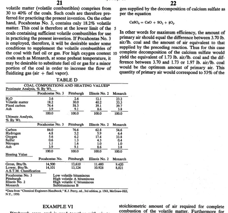
COAL AS FUEL
The present invention provides a means for maintain
ing a highly reducing zone in the lower portion of the
bed while employing coal as the principal fuel for the
reactor. For this purpose, the coal is preferably selected
so that it contains sufficient volatiles to form the reduc
ing gas under controlled conditions. When ?nely
20
25
40
55
65
16
divided coal, such as powdered coal, is introduced into
the lower portion of the reactor bed, the volatile com
bustibles vaporize substantially instanteously. The re
sult is the formation of a gaseous fuel which can be burned under controlled conditions of limited oxygen to
produce a highly reducing gas containing carbon mon oxide and hydrogen. For this purpose, the coal prefera
bly contains at least 25% of volatile combustibles on a
dry mineral matter free basis. Coals containing less than
18% by weight of volatile combustibles are not suitable
for practicing the preferred procedure of the present
invention. When the coal contains volatile combustibles in the range of 18 to 25% (dry mineral matter free ba sis), a reducing gas can be formed under controlled conditions, but the supply of oxygen may need to be limited to such an extent that the primary combustion air may have a lower than optimum volume and veloc
ity for operation of the ?uidized bed. Under such condi
tions, a small proportion of a supplemental fuel provid ing a combustible gas can be introduced into the lower
portion of the bed to supplement the gaseous fuel
formed from the volatile combustibles of the coal. More generally, the amount of supplemental fuel can range from 0 to 30% of the heating value of the coal. The amount of such supplemental fuel can be progressively decreased from 30% downwardly, as the amount of
volatile combustibles from the coal is increased, particu larly in the range above 25% by weight volatiles in the coal. In general, therefore, the process of the present
invention utilizes ?nely-divided coal as a feed to the
lower portion of the reactor, the coal containing at least
18% volatiles, and there may also be introduced a sup
plemental fuel providing volatile combustibles equal to
0 to 30% of the total heating value of the coal as intro
duced, that is, including the volatiles.
As used herein, the term “heating value” refers to the
so-called “higher” or “gross” heating value of a fuel.
There are standard procedures for determining gross
heating values of each type of fuel, such as coal, fuel
gases, and fuel oils. It should be understood that such
procedure is to be followed in determining the gross heating value of the supplemental fuel and of the coal,
thereby establishing that the amount of supplemental
fuel is within the range from 0 to 30% on a gross heating
value basis of the total heating value (including volatile combustibles) of the coal. References describing the
standard test procedures for gross heating value are:
1974 ANNUAL BOOK OF ASTM STANDARDS, Part 26, for solid fuels, D2015-66, Gross Calori?c Value of Solid Fuel by Adiabatic Bomb Calorimeter; for liquid fuels, D240—64 (1973), Heat of Combustion of
Liquid Hydrocarbon Fuels by Bomb Calorimeter; and
for gaseous fuels, D900, Calori?c Value of Gaseous
Fuels by Water Flow Calorimeter, or D1826, Calori?c Value of Gases in Natural Gas Range by Continuous
Recording Calorimeter.
The supplemental fuel may be a fuel gas or a vaporiz able fuel oil. Suitable fuel gases, include natural gases,
which typically include methane as the major compo
nent, or water gas, which is composed principally of carbon monoxide and hydrogen, or a retort coal gas,
composed principally of hydrogen and methane. In
general, any gaseous fuel can be used, containing as the
combustible components hydrocarbon gases, and/or
hydrogen, and/or carbon monoxide. The supplemental
fuel may also be a hydrocarbon oil, which should be at
4,102,989 .
17
oils, such as ASTM Nos. 1 and 2 fuel oils, are desirable. The fuel oil need not be completely vaporizable, since at the temperatures of the ?uidized bed, any non-vapo rizable components will burn or decompose to carbon,
which will burn. The 'vaporizable components of heavier oils, such as residual fuel oils (re?nery still hot
toms) will therefore function in much the same manner as the coal, providing vaporizable components to sup
plement the volatiles of the coal, and additional com:
bustible carbon to supplement the non-volatile carbon
of the coal. Liqui?ed petroleum gases, such as propane,
butane, or mixtures thereof, can also be used.
In an advantageous embodiment, the coal contains at
least 25% by weight volatiles, and provides substan
tially all of the combustible feed to the reactor, there
being no need to introduce supplemental fuel. Since fuel oil or gas are generally in shorter supply than (coal, it is desired to limit the use of such fuels, as much as possi
ble. '
The primary combustion air fed to the lower portion
of the reactor (the reducing zone) may also function as
the ?uidizing air and preferably does so. The primary
air may provide from 20 to 70% of the stoichiometric
quantity of 02 required for complete combustion of the
volatile combustibles of the coal, or if supplemental fuel
is used as described above, for complete combustion of the volatile combustibles and the supplemental fuel.
Since the solid carbon of the coal burns at a slower rate than the volatiles, such control of the primary air can be utilized to maintain an effective reducing zone in the
lower portion of the bed. In certain preferred embodi ments, the operation of the reducing zone in the lower
portion of the bed is optimized by employing a primary
air rate corresponding to 30 to 65% of the stoichiomet
ric quantity of 02 required for complete combustion of
the volatile combustibles and any supplemental fuel. As previously described for other embodiments, sec
ondary air is concurrently supplied to the upper portion
of the ?uidized bed above the level at which the coal and primary air are introduced. The secondary air pro vides suf?cient oxygen to complete the combustion of the volatile combustibles and the non-volatile combusti bles of the coal, as well as the combustion of any supple
mental fuel. The secondary air is controlled to provide
an effective oxidizing zone above the reducing zone for
conversion of CaS to CaO. The optimum volume of secondary air will vary with the operating conditions.
For example, it can range from as little as 30% up to as
much as 85% of the total air (primary and secondary).
As previously pointed out, for optimum thermal and
material efficiencies, the total amount of air supplied to the reactor, including the air supplied to both the reduc ing and oxidizing zones thereof, should be equal to the
stoichiometric quantity of air (on an 02 basis) required
for complete combustion of the fuel to CO2 and H20
less the amount of air equivalent (0,) supplied by the
decomposition of calcium sulfate. Although some addi tional air above this optimum value, as indicated above,
may be supplied to insure complete combustion of the
fuel and to provide a slightly oxidizing off-gas, large
excesses of air result in corresponding losses in thermal
and material efficiencies. The off-gas can be analyzed periodically or continuously in monitoring the process.
Advantageously, the off-gas is substantially free of CO,
HZ, and unburned fuel, while containing a small per centage of O2 (viz. 0.5 to 2.0 mole %).
The average temperatures to be maintained in the
coal-burning ?uidized bed can be in accordance with
5
20
25
35
40
45
60
65
18
the temperature specified in prior US. Pat. Nos.
3,087,790 and 3,607,045, that is, within the range from
2l50° to 2250° F. Temperatures above 2250° F. are not desirable. However, as previously indicated, one of the
advantages of the process improvement of the present
invention is that lower temperatures can be employed
than 2150° F. For example, where the use of lower temperatures is desirable, as where the feed has a ten dency to sinter at temperatures in the range of 2150” to 2250° F., the temperature can be reduced below 2150°
F. Consequently, where a sintering problem is encoun
tered with the feed, it may be desirable to operate at a
temperature in the range of about 1950‘’ to 2225’ F., but
a temperature above 1900° F. is needed. Therefore, in
general, the temperature conditions of reactor beds
employing the features of the present invention are in the range from 1900" to 2250° F. At such temperatures,
the volatile combustibles in the ?nely~divided coal fed to the lower portions of the reactors vaporize substan tially instanteously as introduced.
An embodiment of a coal-burning reactor is illus
trated by the diagrammatic view of FIG. 3. As there
shown, the ?uidized bed reactor 10 comprises a vessel
having a heat-insulating jacket 11. In the lower portion
of the reactor there is provided a ?uidized bed desig
nated generally by the number 12 and in the upper portion a gas space 13. As shown, the CaSO, feed is supplied through the top of the reactor by means of a feed pipe or conduit 14, which extends downwardly to approximately the top of the bed 12. The ?uidized bed
is illustrated as extending to the bottom of the reactor,
the lower horizontally-extending wall 15 of the reactor being provided with a plurality of inlets 16 which con nect by conduits 17 to a supply pipe 18. A mixture of powdered coal and primary air is pneumatically con
veyed to the inlets 16 through the conduit and pipe
system 17, 18. If desired, the inlets 16 may be provided
with nozzles to control the injection of the coal-air mixture. It is desirable to achieve a relatively uniform distribution of the fuel across the bottom of the reactor,
and to employ relatively high gas velocities in the inlet
pipes to avoid back?ow of solids from the ?uidized bed. Where a supplemental fuel oil or gas is used, the vapor ized oil or gas can be mixed with the powdered coal and
primary air, and supplied through the same inlet system 17, 18. Separate inlet pipes can also be used for intro
ducing the supplemental fuel into the lower portion of
the bed, such as for spraying a fuel oil into the bed. Additional air, referred to in FIG. 3 as secondary air is also supplied to a portion of the bed located at a
higher level than that at which the fuel and primary air
are introduced. As shown, the secondary air is intro
duced through a manifold pipe 19 which communicates with the distributor pipes 20 that extend upwardly to an intermediate level within the ?uidized bed 12. A fairly uniform distribution of the secondary air is desirable,
and therefore a sufficient number of secondary inlet pipes will be provided to achieve such distribution over the cross-sectional area of the bed at the level of intro
duction. Means may be‘utilized in conjunction with the secondary air inlets to minimize back?ow of solids, such as turning the upper ends of the secondary inlet pipes
downwardly, or using inlet members, such as porous
refractories.
With this arrangement, as indicated by the labels on FIG. 3, a reducing zone 21 is provided in the lower
portion of the bed, and an oxidizing zone 22 in a portion
4,102,989
19
conditions can thereby be maintained in the lower por tion of bed 12, while oxidizing conditions are main
tained in an upper portion thereof. Immediately adja cent to the outlets from pipes 20, a highly oxidizing condition will be present. As the reducing gases ?ow
upwardly from the lower zone 21, and mix with the air
introduced through pipes 20, the