City, University of London Institutional Repository
Citation
:
Roth, H. R., McClelland, J. R., Boone, D. J., Modat, M., Cardoso, M. J.,
Hampshire, T. E., Hu, M., Punwani, S., Ourselin, S., Slabaugh, G. G., Halligan, S. and
Hawkes, D. J. (2011). Registration of the endoluminal surfaces of the colon derived from
prone and supine CT colonography. Medical Physics, 38(6), pp. 3077-3089. doi:
10.1118/1.3577603
This is the accepted version of the paper.
This version of the publication may differ from the final published
version.
Permanent repository link:
http://openaccess.city.ac.uk/4332/
Link to published version
:
http://dx.doi.org/10.1118/1.3577603
Copyright and reuse:
City Research Online aims to make research
outputs of City, University of London available to a wider audience.
Copyright and Moral Rights remain with the author(s) and/or copyright
holders. URLs from City Research Online may be freely distributed and
linked to.
City Research Online:
http://openaccess.city.ac.uk/
publications@city.ac.uk
Registration of the endoluminal surfaces of the colon derived
1
from prone and supine CT colonography
2
Holger R. Roth
∗, Jamie R. McClelland
∗, Darren J. Boone
†, Marc Modat
∗, M. Jorge
3
Cardoso
∗, Thomas E. Hampshire
∗, Mingxing Hu
∗, Shonit Punwani
†, Sebastien
4
Ourselin
∗, Greg G. Slabaugh
∗∗, Steve Halligan
†and David J. Hawkes
∗5
∗Centre for Medical Image Computing, University College London, UK 6
†Department of Specialist Radiology, University College Hospital, London, UK 7
∗∗Medicsight PLC, London, UK 8
Abstract.
Purpose: Computed tomographic (CT) colonography is a relatively new technique for detecting bowel cancer or
poten-tially precancerous polyps. CT scanning is combined with 3-dimensional image reconstruction to produce a virtual
endolumi-nal representation similar to optical colonoscopy. Because retained fluid and stool can mimic pathology, CT data is acquired
with the bowel cleansed and insufflated with gas and patient in both prone and supine positions. Radiologists then match
visu-ally endoluminal locations between the two acquisitions in order to determine whether apparent pathology is real or not. This
process is hindered by the fact that the colon, essentially a long tube, can undergo considerable deformation between
acquisi-tions. We present a novel approach to automatically establish spatial correspondence between prone and supine endoluminal
colonic surfaces after surface parameterization, even in the case of local colon collapse.
Methods: The complexity of the registration task was reduced from a 3D to a 2D problem by mapping the surfaces
extracted from prone and supine CT colonography onto a cylindrical parameterization. A non-rigid cylindrical registration
was then performed to align the full colonic surfaces. The curvature information from the original 3D surfaces was used to
determine correspondence. The method can also be applied to cases with regions of local colonic collapse by ignoring the
collapsed regions during the registration.
Results: Using a development set, suitable parameters were found to constrain the cylindrical registration method. Then,
the same registration parameters were applied to a different set of 13 validation cases, consisting of 8 fully distended cases
and 5 cases exhibiting multiple colonic collapses. All polyps present were well aligned, with a mean (±std. dev.) registration
error of 5.7 (±3.4) mm. An additional set of 1175 reference points on haustral folds spread over the full endoluminal colon
surfaces resulted in an error of 7.7 (±7.4) mm. Here, 82% of folds was aligned correctly after registration with a further 15%
misregistered by just one fold.
Conclusions: The proposed method reduces the 3D registration task to a cylindrical registration representing the
endolu-minal surface of the colon. Our algorithm uses surface curvature information as a similarity measure to drive registration to
compensate for the large colorectal deformations that occur between prone and supine data acquisitions. The method has the
Keywords: CT Colonography, Image Registration, Computer aided diagnosis and interventions
9
1. INTRODUCTION
1.1. Motivation
10Colorectal cancer is the second-largest cause of cancer mortality in the West, responsible for more than 1 million
11
cases and 639 000 deaths each year1. Early detection and removal of potentially precancerous polyps (adenomas)
12
arising from the endoluminal colonic surface has been shown to significantly reduce the incidence of subsequent
13
colorectal cancer and thus mortality2. Optical colonoscopy (insertion of a video-endoscope into the cleansed colon)
14
is the reference-standard whole-colon diagnostic test and combines diagnosis and treatment (since polyps can be
15
removed). However, the procedure is uncomfortable for the patient, technically difficult to perform, and is occasionally
16
associated with significant adverse events, including colonic perforation3.
17
Computed tomographic (CT) colonography (CTC) is a relatively new alternative technique for imaging the
col-18
orectum which has been shown in large comparative studies to be as sensitive as colonoscopy for larger polyps and
19
cancer4,5. Moreover, studies have shown CT colonography to be more acceptable to patients than colonoscopy6, and
20
to be relatively safe7. As for colonoscopy, the patient usually undergoes full cathartic bowel preparation prior to
imag-21
ing. Subsequently, multi-detector helical CT is carried out with carbon dioxide colonic insufflation of the bowel (via a
22
small rectal catheter) to maximize the attenuation contrast between the endoluminal surface and the colonic lumen.
Im-23
age rendering software is used to reconstruct a 3-dimensional representation of the endoluminal bowel surface; hence
24
the alternative title, virtual colonoscopy8. However, residual stool and fluid (or even normal anatomical variants) can
25
sometimes look like polyps, and some regions of bowel may be under-distended, which impairs image interpretation
26
by radiologists. To counteract this, it is standard practice to image the patient in two positions prone and supine
-27
which redistributes gas and residue within the colon9. By comparing corresponding regions from prone and supine
28
datasets, the radiologist can assess whether a potential abnormality perceived on one dataset is a real polyp (i.e. its
29
position remains the same, indicating fixation to the bowel wall) or retained stool (i.e. it moves). However, the colon
30
is a relatively long tubular structure that is loosely attached to the abdominal wall via variable mesenteric attachments.
31
The result is that the colon often undergoes considerable deformation during patient repositioning10, or even severe
32
local under-distension which can lead to colonic collapse. This complicates the interpretation task; identifying
corre-33
sponding regions of endoluminal surface between prone and supine acquisitions is difficult, prolongs reporting time,
34
and may lead to errors of interpretation. A reliable method for establishing spatial registration between the prone and
35
supine CT colonography datasets has the potential to simultaneously improve diagnostic accuracy and reduce
inter-36
pretation time. Furthermore, its result could be incorporated in computer-aided detection (CAD) algorithms in order
to improve their robustness and accuracy.
38
1.2. Related work
39The earliest attempt at prone-supine registration involve identifying similar distances along an extracted centerline
40
of the segmented colon in both datasets11,12,13,14,15. This line represents the virtual path through the center of the
41
virtual colonic lumen, from anus to cecum. Methods involve linear stretching and shrinkage of the extracted centerlines
42
based on relative path geometries (for example, local maxima on each centerline’s axial coordinate as tie points). Some
43
centerline-based methods can still be effective with colons exhibiting sections of colonic collapse where the segmented
44
colon is disconnected, e. g.13,15.
45
However, these methods provide only one degree of freedom relative to the colonic surface and so can only account
46
for local stretching and shrinking along the length of the colon – they cannot account for torsion or other deformations
47
‘around’ the colon. Hence, they do not account for all the detailed deformation of the colon surface that we are
48
interested in that commonly occurs between prone and supine positioning such as colonic torsion. Furthermore,
49
aligning the centerline between the prone and supine images is restrained to establish the correspondence between
50
the global shapes of the colon between both views. This shape can vary greatly when the patient changes positions and
51
centerline-based methods might experience difficulties.
52
Alternatively, Näppi16 defined several anatomical landmarks, using these to align the two datasets. Anatomical
53
locations that are relatively resistant to deformation, such as the anus or colonic flexures, were identified. Other
54
landmarks, including the cecum and recto-sigmoid junction, were inferred relative to the landmarks already defined.
55
However, identification of a limited number of corresponding points is likely to be insufficient to describe the complex
56
colonic deformations that occur when moving between prone and supine positions.
57
Other feature-based methods account for colonic rotation by using the teniae coli (three discrete muscles running
58
longitudinally along the exterior colonic surface) as an additional feature17,18. However, the teniae coli alone are
59
difficult to extract robustly. As with centerline-based methods, they aim to match the global shape of the colon and
60
then have to interpolate to the surface in order to estimate the deformation of the detailed surface structure.
61
A voxel-based approach has been developed by Suh et al.19. Initially, Suh’s method involves rigid dataset alignment,
62
based on the location of the anus and the flexures followed by generation of an initial deformation field using
63
the centerlines. Level-set distance maps from the colonic surface are then used to drive a non-rigid registration.
64
They reported an error of 13.77 (± 6.20) mm for aligning polyps in 21 patients. In our experience such
voxel-65
based approaches lack robustness as it is very difficult to adequately constrain the registration to prevent physically
66
implausible deformations while still recovering the large and complex deformations that can occur.
67
They extended their method to handle cases with local colonic collapse where the segmentations are disconnected20.
Although they show promise in handling disconnected segmentations, the validation set was limited to 4 CTC cases
69
with only one collapse in one view and fully connected colon segmentation in the other. A reported average registration
70
error of 30.1 mm for 4 polyps suggests limited accuracy. This may be due to their method of handling local collapses
71
which allows the colon to change its topology during the registration. This could cause different structures to appear
72
similar to each other rather than correctly aligning the corresponding anatomical structures, e. g. a fold being flattened
73
rather than shifted.
74
Fukano et al.21aimed to establish correspondence between the detailed colon surface by matching haustral folds
75
extracted from prone and supine data. Although haustral folds can be detected robustly, it is very challenging to
76
establish their correct correspondence between both views as their results indicate. They report 65.1% of corresponding
77
large haustral folds and 13.3% of small haustral folds being matched correctly.
78
Recently, Zeng et al.22presented a method based on conformal mapping combined with feature matching in order
79
to establish correspondences between the prone and supine surface. They detect four flexures and one teniae coli in
80
order to divide the colon surface into five segments and map each segment to a rectangle. Correspondence between
81
prone and supine surfaces is then established for each rectangular segment individually. Therefore the method relies
82
on being able to accurately determine exactly the same segments on the prone and supine surfaces, which can be very
83
difficult even for fully distended colons, and may not be possible for cases with local colonic collapse. Furthermore,
84
they established correspondence between the mapped segments using only a sparse point set of features extracted from
85
some ‘prominent’ haustral folds, which are unlikely to provide an accurate alignment of the detailed colonic surface.
86
Despite these drawbacks, they report promising results with an average 3D error of 5.65 mm using 20 validated pairs
87
of polyps over 6 patients and a average 3D error of 7.51 mm using feature points.
88
1.3. Proposed solution
89The difficulties described in the previous sections motivated us to develop a method that simplifies the task of
90
establishing full spatial correspondence between prone and supine endoluminal colon surfaces. Since the colon is an
91
extremely flexible structure, the registration task requires a non-rigid transformation but should preserve the topology
92
of the colonic wall. Our method reduces complexity by using cylindrical 2D representations of the endoluminal surface
93
extracted from both prone and supine CTC datasets. This enables us to account for the large deformations and twisting
94
that are inevitable between the two positions in 3D as relatively simple deformations of the cylinder.
95
Topologically, the colon is an open-ended cylinder or tube. Hence, any position within the colon can be mapped by
96
two indices: length along the cylinder and angular position. Each 2D point p(x,y)on the cylindrical representation
97
corresponds directly to a 3D point s(x,y,z)in the CTC data. Any measure acquired in 3D and on the surface can be
98
assigned to a corresponding 2D point p which can be used to drive registration. We propose the use of conformal
mapping of the endoluminal colonic surfaces from prone and supine CT colonography to obtain a 2D cylindrical
100
representation. A shape measure is assigned to each 2D point p in order to drive a non-rigid cylindrical registration in
101
the parameterized cylindrical space. This simplifies the registration task compared with full 3D volume registration.
102
This registration is represented as a transformation between two cylinders that includes non-linear stretch along
103
the colon, local rotation and local torsion. We propose a cylindrical implementation of the well-known B-spline
104
registration method23in order to achieve this for fully connected colon and in the case of local colonic collapse.
105
A similar cylindrical B-spline transformation model was recently proposed by Huysmans et al.24in order to produce
106
active shape models of tubular structures (e.g. clavicles, tracheae, and thrombi). Although the transformation model is
107
very similar to the one used in this paper, their application is very different (they are trying to determine correspondence
108
for a large population of shapes), and as such their method of assessing correspondence (the minimum description
109
length of the resulting shape model) and their overall framework for performing the registrations cannot be used for
110
registering prone and supine colonic surfaces.
111
We claim novelty for the first use of a cylindrical non-rigid registration method to align image derived
representa-112
tions of the full colon endoluminal surface in order to establish a correspondence between colon surfaces extracted
113
from prone and supine CTC. Our motivation is to simplify the radiologist’s task in interpreting the two datasets, in
114
particular the assessment of possible polyps in the two views, to reduce the incidence of false positives, speed up
115
interpretation and finally to provide correspondence in emerging computer assisted detection (CAD) applications that
116
merge prone and supine datasets in order to reduce false positive detection rates.
117
2. METHODS
Each surface point on the endoluminal colon surface S can be described with two indices x and y using a cylindrical
118
representation. Here, x denotes a position along the length of the colon and y its angular orientation. Several groups
119
have proposed methods to “unwrap” or “virtually dissect” the colon in order to produce flattened 2D images of the
120
endoluminal surface, which were developed to facilitate more rapid interpretation25.
121
Conformal maps are typically applied to surface mesh triangulations in order to find a simpler representation of
122
the three-dimensional object. They provide a one-to-one mapping of a 3D surface to 2D space while preserving local
123
angles26. These methods are based on differential geometry and ensure conformal mapping of the entire surface while
124
preserving appearance of local structures, e.g. polyps and haustral folds.
125
Our registration approach is based on the following principle: a prone endoluminal colon surface SpinR3can be
126
transformed using the one-to-one mapping fpto a parameterization PpinR2. The supine surface Ssis mapped to Ps
127
through fs, respectively. Here, pands denotes prone and supine respectively. If the necessary transformation Tcyl
128
between Pp and Ps can be determined, the transformation Tps between the surfaces Spand Ss follows as shown in
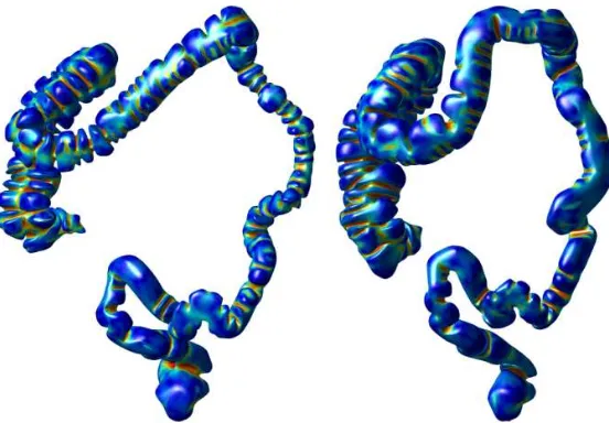
Fig. 1, where the principle is illustrated with the endoluminal colon surfaces extracted from prone and supine CT
130
colonography.
131
FIGURE 1. The principle of colon surface registration between prone and supine CTC using a cylindrical 2D parameterization (for patient 7), where the color scale indicates the shape index (see equation 2) at each coordinate of the surface computed from
the 3D endoluminal colon surfaces. The hepatic and splenic flexures are marked as hfp/s and sfp/s respectively (p/s denotes
prone/supine).
2.1. Colon segmentation
132In order to extract the endoluminal colonic surface S, the inflated lumen L is segmented using the method described
133
by Slabaugh et al.27. This method was developed for segmenting intraluminal gas over the entire colonic length. It is
134
possible that gas-filled regions of small intestine are segmented as either isolated structures or connected to the colonic
135
segmentation. Because we are only interested in the endoluminal surface of the colon, we reject all other objects by
136
first eroding the segmentation with a spherical structure element with radius r to remove erroneous connections if
137
necessary. Then the six-connected object with the largest volume is selected and subsequently dilated with a structure
138
element of radius r in order to restore its original surface dimensions. Here, six-connected refers to an object in 3D
139
voxel space which is only connected to direct neighboring voxels on its six sides. For this study, the radius r was
140
adjusted interactively to produce the best segmentation by visual inspection. The parameter, r, ranged between 1 and
141
5 voxels for all our cases.
142
The rectal insufflation catheter (used to introduce the colonic gas necessary for luminal distension) is often excluded
143
from the segmentation and can therefore lead to errors when extracting the endoluminal surface. We use a combination
144
of morphological operations on a rectal region of interest in order to segment this plastic tube and add it to the colon
145
segmentation L if necessary.
146
2.2. Topological correction
147The colonic lumen L is now represented as a single six-connected object, ideally with a surface of genus zero which
148
is topologically equivalent to a sphere. However, topological errors could be present in the segmentation due to noise
or reconstruction artifacts in the CT colonography data. This occurs particularly at adjacent folds or where the colon
150
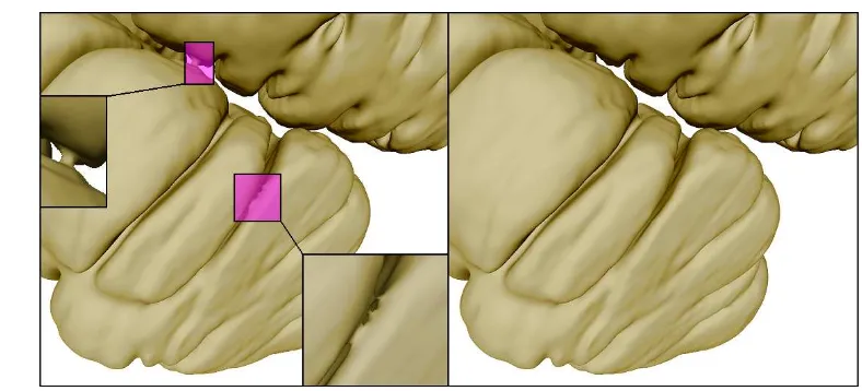
folds back against itself, resulting in erroneous connections in the surface as shown in Fig. 2 (left).
[image:8.595.102.496.112.291.2]151
FIGURE 2. Left: handles and an erroneous connection caused by limitation of the segmentation quality, resulting in incorrect topology. Right: the same surface region after topological correction.
We use a thinning algorithm28,29starting at the centerline (running at the virtual center of the colonic lumen from
152
cecum to rectum) and guided by a distance based priority map. This centerline can be extracted with the method
153
described by Deschamps et al.30based on evolving a wave front through the colon using the fast marching method31.
154
This method of centerline extraction requires a defined start- and end-point. If the insufflation tube has been detected,
155
we use the most caudal point inside the tube. Otherwise the most caudal point in the colonic lumen L is used. This
156
corresponds to the patient’s ano-rectal junction in both projections. A point in the cecum is currently selected manually.
157
Good correspondence for centerline start and end points is not essential for topological correction but improves rectal
158
and cecal mapping to a cylindrical representation as described in section 2.4.
159
The extracted centerline is used to generate an image C with each voxel on the centerline labeled as foreground.
160
A topology preserving region growing algorithm is then applied to the foreground of C maintaining its topological
161
characteristics. In this case, the centerline object is topologically equivalent to a sphere (genus zero). The region
162
growing will thus fill L whilst leaving voxels untouched which would introduce a topological change, e.g. handles.
163
This produces one-voxel-wide cuts through handles at the minimum distance position, resulting in a topologically
164
correct genus-zero segmentation Lcorrof the endoluminal colon lumen (see Fig. 2).
165
2.3. Colonic surface extraction
166The endoluminal colonic surfaces S are then modeled as triangulated meshes on the surfaces of Lcorr, lying on the
167
gas-tissue border in the CTC images. Those surfaces are now guaranteed to be topologically correct (of genus zero).
168
In order to extract S we use the marching cubes algorithm on Lcorrwith a subsequent smoothing using a windowed
sinc function interpolation kernel32. This approximates a continuous surface which facilitates the convergence to a
170
2D parameterization using the Ricci flow method (as described in section 2.4). Furthermore, the mesh is decimated
171
using a quadric edge collapsing method33in order to reduce computation time. Finally, Loop’s subdivision method34
172
is applied in order to achieve approximately uniformly sized and non-skewed faces over the entire surface S. This
173
procedure results in a simply connected genus-zero surface S of the colonic lumen Lcorr. For all cases used in this
174
study, the surface meshes had typical edge lengths of 3.3 (±1.3) mm and about 60,000 faces.
175
2.4. Cylindrical representation of the endoluminal colonic surface
176As described above, the endoluminal colon surfaces S can be modeled as piecewise-linear meshes composed
177
of vertices vi that are connected using triangular faces. Those surfaces S can be parameterized using a discrete
178
conformal mapping method. One method to parameterize arbitrary discrete surfaces was introduced by Hamilton35for
179
Riemannian geometry based on Ricci flow. It deforms the surface proportionally to its local Gaussian curvature similar
180
to a heat diffusion process until it converges towards a desired Gaussian curvature36. Rather than mapping the surface
181
to a rectangle as with other methods22, the Ricci flow does not require a border and therefore reduces distortion. Qiu
182
et al.37 were the first to apply it to a colonic surface using volume rendering for the purpose of visualization, and
183
we follow their approach here with a small modification to the planar embedding (see below). We use Ricci flow to
184
produce a conformal mapping onto a 2D plane. The Ricci flow is defined as
185
dui(t)
dt =
¯
Ki−Ki, (1)
where Ki is the Gaussian curvature at vertex vi, ¯Ki the desired Gaussian curvature and ui a weighting function,
186
computed from a circle packing metric36. Ricci flow can be described as the gradient flow of an energy function38
187
which can be minimized using the steepest gradient descent method. For the purpose of parameterization of the colon
188
surfaces S in two-dimensional space, the target curvature Kishould be zero at all vertices vi.
189
The original genus-zero surfaces S have to be converted to a surface SD of genus one36 for this purpose, e.g.
190
converting a sphere-like surface to a torus-like surface. Therefore, we create holes in the surface mesh by removing
191
vertices and connected triangular faces closest to the previously selected cecal and rectal points. The remaining surface
192
is doubled, inverted and glued with the original mesh onto the vertices and edges along the previously produced holes
193
in a similar manner to39. The resulting surface SD is then parameterized using the Ricci flow while minimizing the
194
global maximum difference error between all current Kiand ¯Ki, Emax. This is computed until Emaxconvergence below
195
a pre-set value, resulting in a mesh P inR2with two-dimensional coordinates of each surface location on S.
196
For all patients used in this study, the Ricci flow was minimized below an error of Emax=1e−6 which results
in a surface mesh with its local Gaussian curvatures Ki tending to zero everywhere. This mesh can be embedded
198
into two-dimensional spaceR2using the resulting edge lengths of each triangle, starting from a random seed face
199
and then iteratively adding neighboring faces, in a similar manner to36. This is achieved by computing the position
200
of each triangle vertex based on the intersection of two circles which have radii equal to the corresponding edge
201
lengths. However, as Ki is not exactly zero at every vertex vi, the resulting accumulated 2D mesh can have cracks
202
and overlapping faces. These errors in computing the planar embedding P can be reduced if the Ricci flow converges
203
towards smaller values of Emax, but needs to be balanced against the computation time required for the Ricci flow.
204
Segments of 2D surfaces, generated from the same endoluminal colon surface after convergence to different error
205
levels Emax, are shown in Fig. 3 (left, middle). However, if the errors in the planar embedding are small enough, the
206
Ricci flow can be stopped and corresponding vertices of neighboring triangles can be joined together by averaging
207
their two-dimensional positions. This results in a closed 2D mesh P without discontinuities as in Fig. 3 (right).
[image:10.595.49.541.77.443.2]208
FIGURE 3. Computed planar embeddings P of the endoluminal colonic surface S with convergence errors Emax=1e−4(left),
Emax=1e−6(middle) and the averaged planar embedding (right) with Emax=1e−6.
The 2D mesh P represents a regular cylinder and can be re-sampled between 0 and 360◦to generate rectangular
209
raster images for use in the cylindrical registration as illustrated in Fig 4. Here, the horizontal dimension x corresponds
210
to a distance along the colon from cecum to rectum and the vertical dimension y to the angular position around the
211
circumference of the colon.
212
FIGURE 4. Sampling the unfolded mesh to generate rectangular raster-images I suitable for image registration. Each band represents a shifted copy of the planar embedded meshes P which are sampled between the horizontal lines to cover a full 360◦of
endoluminal colon surfaces S.
Sampling curvature information onto the parameterization P results in raster-images I for supine and prone
endo-213
luminal colon surfaces as shown in Fig. 5 (top, middle). The top and bottom edges of the images I correspond to the
214
same point on the endoluminal colonic surfaces S, thus representing the endoluminal colonic surface as a cylinder.
[image:10.595.212.403.496.538.2]FIGURE 5. Supine (top), prone (middle) and deformed supine deformed to match prone (bottom) raster images of patient 7 where each pixel has the value of the corresponding shape index computed on the endoluminal colonic surface. The x-axis is the position
along the colon, while the y-axis is its circumferential location. The x-positions for the detected hepatic and splenic flexures are
marked as xhepaticand xsplenic. The location of a polyp is marked before (top) and after registration (middle, bottom). Corresponding
3D renderings are illustrated in Fig. 1.
The chosen resolution ratio of 16 between nx=4096 and ny=256 corresponds approximately to the ratio between
216
the length of the centerline and the average circumference around the colon. For all un-collapsed cases used in this
217
study, the average length was 1.7 m and the average circumference was 10.8 cm, giving a ratio of 15.7.
218
For this resolution nx×ny, any two neighboring pixels correspond to 3D points which are 0.27 (standard deviation
219
0.29) mm apart on average, with 99% of neighboring pixels being less than 1.2 mm apart. This suggest that, even
220
though the circumference of the colon changes along its length, the distortion introduced by mapping S onto a
221
cylindrical image I with constant width is sufficiently small enough over most of the endoluminal colon surface.
222
Therefore, any 3D surface location on S can be interpolated with adequate accuracy. Furthermore, our experiments
223
show that the distortion introduced by this step can be successfully recovered by our cylindrical non-rigid registration
224
(as described in section 2.5).
225
Each pixel of I has a value assigned to it in order to drive a non-rigid registration. These values are estimated (using
226
barycentric interpolation) from the local surface shape index (SI) computed on each vertex viof the three-dimensional
227
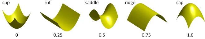
surface S. The shape index SI is a normalized shape descriptor based on local curvature (see Fig. 6) and defined as
228
SI≡1
2− 1
πarctan
κ
1+κ2
κ1−κ2
, (2)
where the principal curvaturesκ1andκ2are the maximum and minimum curvatures computed on the surface S40.
229
The shape index represents the local topological shape of the surface S (as illustrated in Fig. 6). It is a good scalar
230
measure for describing the local structures on colonic surfaces, such as haustra, folds and polyps. It can be also be
231
used for polyp detection41.
FIGURE 6. The shape index SI is a normalized shape measurement to describe local surface structures41.
Corresponding features, like haustral folds, flexures or the teniae coli are clearly visible in both images of Fig. 5
233
(top, middle). These images are now aligned using a cylindrical intensity-based non-rigid registration method which
234
will establish the full spatial correspondence between the endoluminal colon surfaces Spand Ss.
235
2.5. Establishing spatial correspondence between prone and supine datasets
236The two cylindrical representations are now in the same 2D domain but local structures are still misaligned. We will
237
use a non-rigid registration method to align those local structures accurately. In order to provide good initialization for
238
the registration algorithms, we use corresponding surface points at the hepatic flexure (hfp/s) and splenic flexure (sfp/s)
239
to scale the 2D parameterizations linearly along the x-axis (using xhepaticand xsplenic). The flexures are detected based
240
on local maxima of the z-coordinate of the centerline. We detect the hepatic flexure as the first maximum, coming
241
from the cecum, to be above thepatic of the maximum centerline z-coordinate. The splenic flexure is detected as the
242
maximum which is the first to lie above tsplenicof the maximum centerline z-coordinate, relative to the rectum. In order
243
to provide robustness against wrongly detected flexure correspondences, we discard flexures if their centerline distance
244
vary by greater than tvarbetween prone and supine datasets. Based on our experiments, we found good parameters to
245
be thepatic=60%, tsplenic=95% and tvar=5% for all cases used in this study. The corresponding x-positions for the
246
hepatic and splenic flexures are marked as xhepaticand xsplenicin Fig. 5 after linear scaling along the x-direction.
247
The cylindrical representations are used to generate shape index images Ipand Is, where each pixel corresponds to a
248
position on the colon surface in 3D. We establish the alignment between Ipand Isusing a cylindrical non-rigid B-spline
249
registration method. This method is developed from the 3D free form deformation based registration of Rueckert et
250
al.23with the fast implementation provided by Modat et al.42.
251
A standard (non-cylindrical) 2D cubic B-Splines deformation model uses a lattice of control points{~φ}. The spacing
252
between each control point is uniform and noted asδxandδyalong the x- and y-axis respectively. For each pixel~x in
253
the domainΩof the target image. the deformation T2D(~x)can be computed as:
254
T2D(~x) =
∑
i,j
β3
x
δx
−i
×β3
y
δy
−j
×~φi j, (3)
whereβ3represents the cubic B-Spline function.
255
In order to account for the cylindrical nature of the registration we modified the transformation model in a similar
fashion to Huysmans et al.24. For standard B-spline registrations the control point grid must extend outside the image
257
by at least one control point spacing in each direction so that the deformation is defined over the whole image. For
258
the cylindrical registrations, the control point grid does not extend outside the images in the y-direction (around the
259
cylinder). Instead, when an extended control point is required, the corresponding value is taken from the opposite side
260
of the grid. Therefore the equation for the cylindrical deformation is:
261
Tcyl(~x) =
∑
i,j
β3
x
δx
−i
×β3
y
δy
−j
×~φik, (4)
where the control point is indexed by k instead of j, and k is defined as:
262 k=
j+Nδy if j<0
j if 0≤j<Nδy
j−Nδy if j≥Nδy
(5)
Here, Nδyis the number of control points in the y-direction.
263
In addition we prevent any displacement in the x-direction (along the colon) at each end of the image by fixing the
264
x-displacement of the first and last three control points to be zero. This ensures that the ends of the images are aligned
265
with each other, while still allowing for twists around the colon.
266
The two cylindrical shape index images Ipand Is are aligned by finding the transformation which maximizes the
267
objective function:
268
OIp,Is Tcyl
;{~φ}= (1−λ−µ)Csimilarity−λCsmooth(Tcyl)−µCvolpres(Tcyl) (6)
which combines a similarity measure, Csimilarity, and two penalty terms, Csmoothand Cvolpres, weighted against each
269
other by the user-specified weightsλ andµ. The similarity measure used was the mean sum of squared differences
270
(mean SSD):
271
Csimilarity=−
1
NSSD=−
1
N~x
∑
∈Ω
Ip(~x)−Is Tcyl(~x)
2
. (7)
where N=nx×nyis the number of pixels.
272
Two constraint terms were used to try and prevent unrealistic deformations. The bending energy describes the
273
smoothness of the deformation and is defined as:
274
Csmooth=
1
N~x
∑
∈Ω
∂2T
cyl(~x)
∂x2
2 +
∂2T
cyl(~x)
∂y2
2 +2
∂2T
cyl(~x)
The volume-preserving penalty term discourages large expansions/contractions, and is defined as:
275
Cvolpres=
1
N~
∑
x∈Ω
log det(Jac Tcyl(~x) 2
(9)
In addition we prevent folding occurring by introducing a folding correction scheme performed concurrently with
276
the registration process43. For each voxel that corresponds to a negative Jacobian determinant we compute its influence
277
on its neighborhood control points and change the control point positions until the determinant value is positive.
278
In order to find optimal parameters for the B-spline registration, we used a sub-set of the available cases for tuning
279
the registration algorithm parameters. The following reported optimal parameters were found empirically by visual
280
examination of the registration results and by assessing the alignment of polyps after registration.
281
We used a coarse-to-fine approach in order to capture first the largest deformations and then the smaller differences
282
between both input images. This is achieved with a seven-level multi-resolution approach using Ipas target and Is as
283
source. Both the image and B-spline control point grid resolutions are doubled with increasing resolution levels. The
284
final resolution level uses images with 4096×256 (nx×ny) pixels. The control point spacingδ is 16 pixels in both
285
directions at each resolution level. The gradient of the cost function is smoothed after each iteration, using a Gaussian
286
kernel with a standard deviation of 3δ. Gaussian smoothing of the 2D images is applied at each resolution level with a
287
standard deviation of two pixels. The objective function weights are set toλ =1e−4andµ=1e−4. These parameters
288
were found to recover the majority of the deformation between the two images for the data used for tuning, while
289
preventing unrealistic deformations from occurring.
290
The cylindrical B-spline registration results in a continuous transformation around the entire endoluminal colon
291
surface and allows the mapping between Spand Ss. From this mapping it is straightforward to determine the full 3D
292
mapping Tps(as shown in Fig. 1).
293
2.6. Dealing with collapsed colon
294Despite adequate colonic insufflation, short segments of colonic collapse commonly occur, particularly when the
295
patient changes position from supine to prone. Furthermore, residual colonic fluid due to suboptimal bowel preparation
296
can occlude the colonic lumen, resulting in more than one colonic segment for 3D reconstruction. If the colon is locally
297
severely under-distended, the segmentation method described in section 2.1 can lead to disconnected colon segments.
298
Most 3D workstations allow the radiologist to manually choose the order in which the centerline connects these
299
disconnected colonic segmentations. Fig. 7 shows a patient’s colon with a collapse in the descending colon (DC) in
300
the supine position. While some centerline-based methods can handle local colonic collapse, they only provide a 1D
301
correspondence along the centerline. To the best of our knowledge, only Suh et al.20have attempted a 3D registration
of images where the colon is collapsed in only one view but report limited accuracy.
303
If the collapsed segment is relatively straight, its length can be estimated as the Euclidean distance between the
304
centerlines of the well-distended segments. The length of each well-distended segment is estimated based on the
305
length of its centerline. We currently select the beginning and end points, as well as the correct order of each segment,
306
manually. The angular alignment between each segment was determined as the shift around the y-axis which minimizes
307
the 3D distance between points with the same angular orientation on either side of the collapse. The cylindrical images
308
I of such a case (patient 17) are shown in Fig. 8. It can be seen that despite the missing data in the collapsed section of
309
the descending colon, we can register both supine colon segments with the fully distended prone endoluminal colon
310
surface reasonably well.
[image:15.595.163.446.254.483.2]311
FIGURE 7. A case where the descending colon is collapsed in the supine position (marked, right image) but fully distended in the prone(left).
FIGURE 8. Cylindrical representation as raster images of the collapsed supine (top), prone (middle) and deformed supine (bottom) endoluminal colon surface of patient 17. The location of a polyp is marked before (top) and after registration (middle,
[image:15.595.75.542.524.622.2]3. CLINICAL EVALUATION
Ethical permission was obtained to utilize anonymized CT colonography data acquired as part of normal day-to-day
312
clinical practice. CT colonography had been performed in accordance with current recommendations for good clinical
313
practice9and any detected polyps subsequently validated via optical colonoscopy. For the purpose of establishing
314
spatial correspondence across complete endoluminal surfaces, we selected 24 patients where the colon was not
under-315
distended in both the prone or supine positions and who had either fluid ‘tagging’ (the increased radio-density allows
316
‘digital cleansing’ of residual fluid) or little remaining fluid. This allowed a continuous segmentation over the full
317
length of the colon using the methods described in section 2.1.
318
The datasets were randomly allocated into development and validation sets (using random permutation), with 12
319
cases each. During the course of the development, we discovered that it is difficult to identify corresponding features
320
by eye in the cylindrical image representations for some cases. Closer examination revealed that this was due to
321
either large difference in distension of the colon in the prone and supine views or to insufficient fluid tagging.
322
Large differences in distension can lead to considerable local dissimilarity of surface features, such as folds. Fig.
323
9 and 10 show such a case with marked differences in cylindrical representations Ipand Is(Fig. 9, top and bottom),
324
resulting from very different distensions (Fig. 10). These can occur only partially or over the full extent of the colon.
325
Furthermore, differences in the colon surface can occur due to insufficient fluid tagging for accurate digital cleansing.
326
This also leads to artifacts in the segmentation. We identified 4 development datasets with marked differences in
327
local distension, which therefore had different surface features and these were excluded from the study, leaving 8
328
development cases (patients 1 to 8). The development set was used to tune the registration algorithm parameters (as
329
described in section 2.5).
330
FIGURE 10. Different amounts of distension in prone and supine view cause differences of local features in the cylindrical images.
Furthermore, this observation led us to exclude another 4 cases of the validation set which showed large differences
331
in the cylindrical images. Of those, 2 showed marked differences in distension, 1 case showed insufficient fluid tagging
332
and 1 case showed both problems. This resulted in a total of 8 data sets with fully connected colon segmentations in
333
both views for validation (patients 9 to 16).
334
Recognizing the problems introduced by cases with marked differences in distension, we selected another 5 cases
335
for validation of the method on cases with local colonic collapse (patients 17 to 21). Here, the distension and surface
336
features of the 3D endoluminal surfaces S were judged by eye to be sufficiently similar in the well-distended segments
337
before execution of the registration algorithm. This selection process results in a total of 13 cases used for validation,
338
as described in the following sections: 8 fully connected sets and 5 with local colonic collapse. In order to assess the
339
spatial accuracy of the proposed registration method, we use clinically validated polyps and haustral folds to measure
340
the registration error.
341
3.1. Validation using polyps
342Experienced radiologists identified polyps in both prone and supine CT colonography scans using 2D
multi-343
planar reformats and endoscopy data for guidance. The polyps’ endoluminal extent was labeled to provide reference
344
coordinates for validation. Polyp labels were checked and corrected if necessary and then matched by eye between the
345
prone and supine view by an experienced colonography radiologist (DJB).
346
The cases were selected to present a widespread distribution of polyps throughout the colonic length so that
347
registration accuracy could be investigated over the entire endoluminal surface. Crucially however, any polyps were
348
masked in the 2D cylindrical images I such that those pixels lying on or close to the polyp were ignored during
registration when computing the similarity measure Csimilarity. Thus, it was impossible for the polyps used for validation
350
to bias the registration results. Fig. 11 illustrates masking of polyps.
[image:18.595.161.449.115.225.2]351
FIGURE 11. Masking of polyps to ensure they do not influence subsequent registration: polyps in unfolded view (left). Masked polyps (right) to be ignored in registration. The center of mass c which is used as a reference point is marked with a cross.
In order to determine registration error, we identified a pair of reference points for each manually matched polyp in
352
the prone and supine views. The reference points were defined as the points at the center of the intersecting surface
353
between the extracted endoluminal colon surfaces S and the segmented polyps. Therefore, these points lie on the
354
surfaces Spand Ssrespectively. The center point c(x,y)is computed as the center of mass of the intersecting pixels in
355
the 2D images I, as indicated in Fig. 11 (right). Each 2D reference point c(x,y)corresponds to a 3D point ci′(x,y,z)on
356
the surfaces S which lies inside the polyp’s volume. We then determined the registration error in mm by transforming
357
each reference point c′son Ss using the 3D mapping Tpsto find Tps(c′s), which lies on surface Sp, and computing the
358
3D Euclidean distance to c′p, which also lies on surface Sp.
359
All 8 datasets used to fine-tune the algorithm had clearly corresponding features in both prone and supine 2D
360
representations, such as patient 7 in Fig. 5 (top, middle). It can be seen that after cylindrical B-spline registration, the
361
corresponding features are well aligned (Fig. 5, bottom). The corresponding 3D renderings are illustrated in Fig. 1.
362
Polyps of the same case and corresponding virtual endoscopic views after their prone and supine views were aligned
363
using the registration result are shown in Fig. 12 and Fig. 13.
364
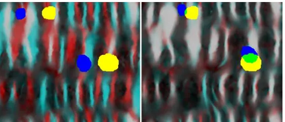
FIGURE 12. Overlay of masked out polyps before (left) and after (right) establishing spatial correspondence. The prone image is colored red with a yellow polyp mask, and the prone is colored cyan with a blue polyp mask. After establishing spatial
[image:18.595.168.450.518.639.2]FIGURE 13. Polyp localization for patient 7 after registration using the prone (left) and supine (right) virtual endoscopic views. The black dot shows the resulting correspondence in the 2D (bottom) and 3D (top) renderings.
We used the same registration parameters as optimized using the development set (patient 1 to 8) on the validation set
365
(patients 9 to 21). Table 1 shows the results of assessing the registrations using the polyps of the 13 validations sets. The
366
error after the cylindrical parameterization but before the B-spline registration is denoted Polyp Parameterization Error
367
(PPE ), and the error after the B-spline registration is denoted Polyp Registration Error (PRE ). Before calculating
368
PPE the images are translated in the y-direction (around the colon) to minimize the SSD between the images, as the 0
369
degrees position is arbitrarily assigned by the cylindrical parameterization.
370
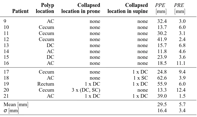
TABLE 1. Registration error in mm for 13 polyps in the 13 patients used for validation of the registration method. These included 8 fully connected cases (patients 9 to 16) and 5 cases with local colonic collapse (patients 17 to 19). The Polyp Parameterization Error (PPE ) gives the error in aligning the polyps after cylindrical parameterization but before registration, the Polyp Registration Error (PRE ) gives the error after cylindrical registration.
Patient
Polyp location
Collapsed location in prone
Collapsed location in supine
PPE [mm]
PRE [mm]
9 AC none none 32.4 3.0
10 Cecum none none 13.7 6.0
11 Cecum none none 30.2 3.1
12 Cecum none none 41.9 2.4
13 DC none none 15.7 6.8
14 AC none none 11.8 4.6
15 DC none none 23.9 3.6
16 AC none none 18.5 11.1
17 Cecum none 1 x DC 24.8 9.4
18 AC none 1 x SC 62.6 3.9
19 Rectum 1 x DC 1 x DC 55.9 6.0
20 Cecum 3 x (DC, SC) none 13.3 12.4
21 AC 1 x DC 1 x DC 39.0 1.5
Mean[mm] 29.5 5.7
σ[mm] 16.4 3.4
The PRE had a mean (±std. dev.) of 5.7 (±3.4) mm for 13 validation patients with a single polyp each, and all 13
371
polyps were well aligned. The PPE results show that cylindrical parameterization on its own is not enough to align the
[image:19.595.143.470.463.657.2]datasets – the cylindrical non-rigid B-spline registration is required for accurate alignment. This result is sufficiently
373
accurate to direct the radiologist to an area of the endoluminal surface, which is close to the suspected lesion in both
374
views, even in the case of local colonic collapse (patients 17 to 21).
375
The hepatic flexure were not used to initialize the registration for patient 12 and patients 18-20, as the distances
376
along the centerline between prone and supine varied more than tvar(here, 5%). However, the cylindrical registration
377
was still able to align features well.
378
The resulting error for 9 polyps in the 8 development cases was 6.6 (±4.2) mm after non-rigid registration (PRE )
379
and therefore slightly higher than PRE of the validation set. The polyps for development of the registration method
380
occurred in the ascending colon (AC), transverse colon (TC), descending colon (DC) and sigmoid colon (SC).
381
3.2. Validation of spatial correspondence along the entire length of the colon
382Polyps can give definite points of correspondence on the colon surface and give a good estimate of the registration
383
performance. However, their number is limited to only one polyp per case in our validation set. In order to assess
384
the registration quality over the entire endoluminal colon surface, corresponding haustral folds were chosen from the
385
prone and supine datasets. Reference point coordinates were provided to lie centrally on the fold in both views; the
386
haustral fold centers were automatically calculated by first segmenting each fold on the colon surfaces S using a
graph-387
cut method44based on the principal curvaturesκ1andκ2. Then, the center of each fold was computed as the vertex
388
which has the lowest maximum distance to any vertex on the border of the segmented fold.
389
Using the cylindrical representations to establish regions of likely correspondence and virtual colonoscopic views
390
for assurance, a radiologist (DJB, with experience in over 500 validated colonography studies) then manually identified
391
corresponding folds from the prone and supine views. Any folds where the radiologist could not be certain of
392
correspondence were not used for validation, but this still provided an average of 90 pairs of corresponding folds per
393
patient, with a total of 1175 pairs over all 13 validation cases (patients 9 to 21). The center points of the corresponding
394
folds were then used as corresponding reference points for assessing the registration.
395
Fig. 14 shows the normalized distributions of reference points versus a normalized position along the centerline
396
from cecum (0.0) to rectum (1.0) for 8 un-collapsed and 5 cases exhibiting local colonic collapse. The decline in
397
number of reference points is due to the fact that there are naturally fewer folds in the left hemi-colon.
0 0.2 0.4 0.6 0.8 1 0
0.05 0.1 0.15 0.2 0.25 0.3 0.35
Position along centreline (cecum to rectum)
Normalized histogram
[image:21.595.172.424.87.289.2]8 un−collapsed cases: 774 data points 5 collapsed cases: 401 data points
FIGURE 14. Normalized distributions of reference points normalized along the centerline from cecum to rectum for un-collapsed and collapsed cases.
We assess the Fold Registration Error (FRE ) in the same way as described in section 3.1 but using the haustral
399
fold centers as reference points. Using this large set of reference points, the FRE was 7.7 (±7.4) mm for a total
400
of 1175 points distributed over all 13 validation patients. In comparison, just using the cylindrical parameterization
401
on its own (before B-spline registration) a Fold Parameterization Error (FPE ) results in an error of 23.4 (±12.3)
402
mm. A histogram of the registration error (FRE ) is shown in Fig. 15. Here, the normalized distributions of FRE for
403
un-collapsed and collapsed cases are colored differently and displayed next to each other for comparison. It can be
404
seen that the majority of points (95%) lie below an error of 22.8 mm, with a maximum error of 44.1 mm. However,
405
the FRE is slightly higher for the 5 collapsed cases with 9.7 (±8.7) mm as opposed to the 8 un-collapsed cases with
406
FRE of 6.6 (±6.3) mm.
407
Using our method haustral folds are almost always aligned with another haustral fold in the other image, but this is
408
not always the correct corresponding fold. Using the segmented haustral folds we could analyze how many of the folds
409
were aligned with the correct corresponding fold, and how many were misaligned by one or more fold. 82% of all 1175
410
reference points were assigned to the correct corresponding fold. 15% of reference points were misaligned by just one
411
fold and 3% misaligned between two and three folds. This assumes that the radiologist correctly labeled corresponding
412
haustral folds. We have no way to assess this but it is likely that at least some of the apparently misregistered data is
413
due to this observer error. Nevertheless the identification of corresponding haustral folds is high.
414
In agreement with the FRE results, 71 % of haustral folds were correctly matched in the 5 cases with local colonic
415
collapse. Whereas 88% of haustral folds in the 8 un-collapsed cases were assigned to the correct corresponding fold.
416
The slight decline in registration quality of cases exhibiting local colonic collapse is due to the fact that, typically, the
417
colon distension varies in the areas close to the collapse, e. g. the surface area of the descending colon in Fig. 7. Again,
this introduces marked difference in the local surface features which degrades the registration accuracy in these areas.
419
0 5 10 15 20 25 30 35 40 45
0 0.02 0.04 0.06 0.08 0.1 0.12 0.14 0.16 0.18
Registration error in mm
Normalized histogram
[image:22.595.133.465.114.390.2]8 un−collapsed cases: 774 data points 5 collapsed cases: 401 data points
FIGURE 15. Normalized histograms of the Fold Registration Error (FRE ) distributions in mm using reference points spread over the endoluminal colon surface for un-collapsed and collapsed cases.
4. DISCUSSION
We have presented a novel method for establishing spatial correspondence between endoluminal colonic surfaces
ex-420
tracted from prone and supine CT colonography data. Our method simplifies the problem of aligning the prone and
421
supine surfaces from a 3D to a 2D task. This is achieved by mapping the full endoluminal surface to a cylindrical
422
parameterization using a conformal mapping. The novel contribution of this work is that we use these cylindrical
423
parameterizations in order to align the endoluminal colon surface using non-rigid B-spline registrations. Cylindrical
424
raster-images with shape index values derived from the initial 3D surfaces are used to drive the registration. This
425
process can establish accurate correspondence between the 2D cylindrical parameterizations, and hence give
corre-426
spondence over the full 3D colonic surfaces which is able to recover the large colonic deformations and torsion that
427
occurs between the two acquisition positions.
428
Our approach is motivated by the assumption that the overall shape of the colon can undergo large deformations
429
when the patient changes position, but that the local shape of surface structures, such as haustral folds, remains similar
enough between scans to align the surfaces. During the development of our method we discovered that for 8 of the
431
24 un-collapsed cases there were large regions where the surfaces structures appeared markedly different between the
432
two scans. These were due to large differences in the distension of the colon or insufficient fluid tagging. We decided
433
to exclude these cases from this study as we expect our current method to fail for such cases. However, we strongly
434
suspect that most other methods presented in the literature that aim to generate accurate correspondence over the
435
colonic surface (i. e. the feature based methods22 and the voxel based methods19,20) will also experience difficulties
436
with cases where the surface features appear differently in the two scans. The number of such cases observed in this
437
study indicates that these cases are not infrequent, and methods that can address these cases must be developed to
438
achieve maximum clinical benefit.
439
Another common occurrence is for there to be some regions of local colon collapse in one or both scans. Validation
440
of our proposed registration method on 5 cases where there was a collapse in at least one view showed promising
441
performance. It shows that the method is able to handle cases with multiple collapses in both views. Some of the
442
centreline based approaches can handle regions of local collapse, but these only give approximate correspondence
443
based on the shape of the centreline, and do not attempt to provide accurate correspondence over the colon surface.
444
To the best of our knowledge there has only been one other method proposed to date that attempts to provide accurate
445
correspondence over the colon surface (as opposed to just at the centreline) and to handle regions of local colon
446
collapse20. However, this method has not yet been validated on cases with multiple collapses in both views as we
447
have. Furthermore, their results show limited accuracy.
448
The method presented here relies on extracted colon surfaces of good quality. Therefore, pre-processing steps of
449
segmentation (which involved manual interaction) and automated topological correction were necessary to extract
450
topologically correct surfaces for the patient data used here. It is clear that obtaining good quality segmentations of the
451
intraluminal colon surface reliably and robustly is a significant impediment to the clinical adoption of our method. We
452
will therefore be devoting more resources to improving and automating our segmentations, both at the image analysis
453
stage but also during patient preparation and data acquisition. Future work will extend the concepts described in this
454
paper to cases of markedly different distensions between prone and supine colonography, insufficient tagging and
455
automatically handling regions of local under-distension with more complex collapses. Although quality control of
456
CT colonography is improving, these remain common problems in routine clinical practice.
457
The current method requires some manual interaction. These are: 1) choosing the structure element sizes
inter-458
actively in order to correct the colon segmentations and include the the rectal insufflation catheter while visually
459
inspecting the segmentation quality. 2) We selected the start and end-point as well as the correct order of each
well-460
distended colon segment. Standard commercial 3D workstations already require the radiologist to manually choose the
461
order of each colon segment. These steps are relatively quick to perform and require minimal manual input. Therefore
462
we did not consider these few manual interactions to be a major impediment to our proposed method. However, We
will further investigate how individual colon segments can be arranged automatically in the case of colonic collapse.
464
This will also incorporate methods of detecting two corresponding points at each segment which defined the start and
465
end of each parameterized cylinder.
466
Given topologically correct surface meshes of the size used in this study, our single processor implementation of
467
the Ricci flow conformal mapping (using the steepest gradient descent minimization) currently takes several hours
468
to achieve sufficient convergence. However, faster solvers such as the Newton method36or a GPU-based
implemen-469
tation37can speed up the computation considerably. Alternatively, other conformal mapping methods could be used,
470
e.g.45which require less computation time. It should be made clear that obtaining the cylindrical parameterization was
471
not the focus of this study. There have been a number of parameterization methods presented in the literature, some
472
based on conformal mappings26,45,39and some on other techniques46, and we simply chose one that would generate an
473
appropriate mapping for us to use. Future work will investigate faster implementation of the Ricci flow as well as
alter-474
native techniques for generating the cylindrical parameterizations, in order to produce appropriate parameterizations
475
in a clinically feasible time frame.
476
In contrast to the cylindrical parameterization, the cylindrical B-spline registration, provides a result within a few
477
minutes, which is fast enough to be clinically useful. A multi-resolution-level registration approach was used in order
478
to help the registration optimization avoid getting stuck in local minima and to reduce the computation time. However,
479
our validation shows that some haustral folds were misaligned by one or more folds indicating that the registrations
480
were occasionally still getting trapped in local minima. Future research will investigate how better initialization of the
481
cylindrical registration and/or a better choice of registration parameters could solve this problem.
482
In conclusion we have provided a framework for the alignment of information from prone and supine CT
colonog-483
raphy; a very challenging registration problem. The method comprises conformal mapping of CT derived features onto
484
a cylindrical surface, followed by a cylindrical registration of these features. This establishes an estimate of a dense
485
correspondence throughout the derived colon surface. The results show promise, not only for polyp detection but also
486
for establishing correspondence between corresponding haustral folds on a limited set of colonography datasets.
487
ACKNOWLEDGMENTS
We gratefully acknowledge financial support for this work from Medicsight PLC, the NIHR program: ‘Imaging
488
diagnosis of colorectal cancer: Interventions for efficient and acceptable diagnosis in symptomatic and screening
489
populations’ (Grant No. RP-PG-0407-10338) and the EPSRC-CRUK Comprehensive Cancer Imaging Centre of UCL
490
and KCL (Grant No. C1519AO).