On-chip Electrical Modulation of Phase Shift between OAM Beams with
Opposite Topological Charge
Huanlu Li,
1,2Michael J. Strain,
2, 3Laura Meriggi,
2Lifeng Chen,
1Jiangbo Zhu,
1Kenan Cicek,
1Jianwei Wang,
4Xinlun Cai,
4, 5,a)Marc Sorel,
2Mark G. Thompson,
4and Siyuan Yu
1,5,b)1
Department of Electrical and Electronic Engineering, University of Bristol, University Walk, Bristol, BS8 1TR, UK
2
School of Engineering, Rankine Building, Oakfield Avenue, University of Glasgow, Glasgow G12 8LP, UK
3
Institute of Photonics, University of Strathclyde, Wolfson Centre, 106 Rottenrow East, Glasgow G4 0NW, UK
4
Centre for Quantum Photonics, H. H. Wills Physics Laboratory and Department of Electrical and Electronic Engineering, University of Bristol, Bristol BS8 1UB, UK
5
State Key Laboratory of Optoelectronic Materials and Technologies and School of Physics and Engineering, Sun Yat-sen University, Guangzhou 510275, China
A new approach to electrical modulation of relative phase between two optical vortices with opposite chirality has been demonstrated on a
silicon-on-insulator (SOI) substrate. The device consists of a silicon-integrated optical vortex emitter and a phase controlled 3dB coupler.
The relative phase between two optical vortices can be actively modulated on chip by applying a voltage on the integrated heater. The
phase shift is shown to be linearly proportional to applied electrical power, and the rotating angle of the interference pattern are observed to
be inversely proportional to topological charge. This scheme can be used in lab-on-chip, communications and sensing applications. It can
be intentionally implemented with other modulation elements to achieve more complicated applications.
The concept of angular momentum was first discussed by Poynting in 19091 and it was realized that circular polarized light has angular
momentum, which is spin angular momentum (SAM) of ± ℏ per photon. Until 1992, Allen et al. recognized that light beams with an
azimuthal phase dependence of exp(𝑖𝑙𝜙) carries orbital angular momentum (OAM) independent of the polarization state2. 𝑙 is the
topological charge that can take any integer value and 𝜙 is the azimuthal coordinate. The significance of Allen’s study was that OAM was
a natural character of all helical phased beams, and may lead to a wide range of applications. Various methods have been established to
produce light with OAM, such as spiral phase plates (SSP)3, diffractive optical elements4,5, mode converters6,7 sub-wavelength gratings8,
and nano-antennas9.
_____________________________
a)
Electronic mail: [email protected].
2
In many applications10,11, the capabilities to generate two collinear OAM beams and to modulate the relative phase between OAM beams
are highly desirable in optical manipulations and transmission systems12,13. For example, D'Ambrosio et al. overlapped two OAM beams
with the topological charge of ±𝑙 to generate so-called 'photonic gears', which greatly enhanced the angular measurement precision. In
parallel with this work, M. P. J. Lavery et al. demonstrated a way to detect the angular speed of a spinning object using two OAM beams
with opposite values of𝑙. However, the superposition of the OAM states are generated by bulky and expensive components, like SLM,
which limits the prospect of its wide use in future photonic technology.
In 2012, X. Cai et al. developed a novel optical OAM beam emitter based on 𝜇𝑚-sized micro-ring resonators. The principle of operation
of this integrated OAM device is to couple the rotating whispering gallery mode (WGM) of micro ring resonator to a vertically emitted
propagating OAM mode. By matching the wavelength of the light with the micro-ring resonator, and by detuning from the Bragg grating
resonance, this devices is capable of emitting a propagating field of any desired OAM state. Shortly after, the design was further refined by
integrating resistive heating elements on the waveguide, such that the fast switching of OAM modes could be achieved14.
In this work, we demonstrate an integrated approach to simultaneous generation of a pair of OAM modes with opposite topological charge
by integrating the micro-ring OAM device with phase controlled 3dB couplers. The relative phase between two OAM beams can be
actively modulated on chip by only applying a voltage on the heater integrated with the waveguide.
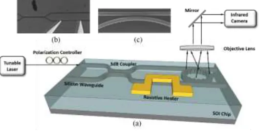
FIG. 1. (a) Schematic of the phase modulated OAM emitter, (b) the optical image of the 3dB coupler and the thermal heater, (c) the SEM images of the ring and access waveguide.
The experimental setup of the waveguide-based ring emitter device is illustrated in Fig. 1(a). The device was designed and tested in
University of Bristol and fabricated in University of Glasgow. It was fabricated on a silicon-on-insulator (SOI) substrate with silicon
waveguides (500 nm wide, 220 nm thick) and a 2𝜇𝑚 buried oxide layer. The ring was defined with a radius of 36 mm with 360 grating
[image:2.612.174.439.425.561.2]3
wavelength of 1530 nm. The width of the grating elements is 60 nm; that is about 1/10 of the grating period. The gap between the ring and
the straight waveguide is 200 nm. The structures were defined using direct-write electron-beam lithography in a Hydrogen Silsequioxane
(HSQ) negative photoresist layer, followed by a Reactive Ion Etching (RIE) process to transfer the Photonic Integrated Circuit (PIC)
pattern into the silicon layer. Subsequently, a layer of silicon dioxide 900 nm thick was coated onto the wafer as the buffer layer between
the silicon layer and metal contact layers. The thermo phase shifter was produced with 50 nm of nickel chromium. A 200 nm thick Au
layer was then patterned as the electrical transmission lines to the heater element. The output waveguide is tapered at both ends of the
access in order to allow more efficient coupling from the input fibre and to reduce the Fabry-Perot resonance effects caused by optical
reflection from the facets.
A fibre-optic polarization controller is used to adjust light into the quasi-TE mode. By splitting the input power with a 3 dB coupler, the
light from the high precision tunable are injected into both clockwise (CW) and counter-clockwise (CCW) directions of the micro-ring,
therefore two complementary OAM beams with opposite topological charges are emitted. The resistive thermal heater, located on one of
the input waveguides, modulate the relative phase of the light in two waveguides and hence the relative phase between the two OAM
beams. Fig. 1(b) shows the optical image of the waveguide based 3dB coupler and the resistive heater. A scanning electron microscope
(SEM) image of a part of the micro-ring with inside gratings has shown in Fig. 1(c).
The output of the device is a superposition of two OAM beams, and the transverse field components of a emitted OAM beam can be
expressed as1516:
2
, 1 1
2 2
A ,
exp
E j j J J
(1)
1 2
, 1 1
2 2
A ,
exp
E j j J J
(2)
where the constant APAq/ 80R3 , the propagation phase factor
2 2
, exp j 2 1 2
, and
i i
J J
denotes the ith order Bessel function of the first kind. In the case of the superposition of two emitted beams,the field components from the interference between the two OAM beams with opposite topological charges and an initial
4
2
, , 2 2 1 1
A ,
exp( ) 2 sin exp( )
2 2
E E j E j j j J J
(3)
2
, , 1 1
2 2
A ,
exp( ) 2 cos exp( )
2 2
E E j E j j j J J
(4)
The intensity distribution then becomes:
2 4
2 2
2 2 2
1 1 1 1
2 2
4A
2 cos 2 T
E E E J J J J
(5)
The device has been characterized at room temperature. The emission spectrum for the device is measured by scanning the
wavelength of the input laser as shown in Fig. 2(a). The mode splitting at 1545nm is caused by the cross coupling between
the lights in two propagating directions in the ring. The strongest coupling exist at 𝑙 = 0 because of the second order Bragg
reflection so it could be used as the signature of the 𝑙 = 0mode17. At each resonance in the shorter or longer wavelength
from𝑙 = 0, a pair of OAM beams with opposite 𝑙 are emitted. These two OAM beams interfere with each other, forming a
petal pattern with 2|𝑙| lobes in the azimuthal direction, as shown in Fig. 2 (b), with un-biased resistive heater. It can be seen
that the measured results agree well not only with theoretical analysis in Eq. (5) but also numerical simulations in Fig. 2 (c).
The diffracted pattern for the emitted two OAM beams forms the fringe pattern with the number of 2|𝑙| radial petals.
[image:4.612.174.442.454.640.2]5
To change the relative phase between the ±𝑙 beams, a voltage between 0-5.2 V (corresponding to dissipated power of 0-20.8 mW) is
applied to the thermal heater by wire bonding the on-chip transmission lines. The resistive heater had a series resistance of 1.5𝑘Ω. The
value of term𝜃 in Eq. (5) then changes with the applying voltage so that the phase shift is manifested in the rotation of the interference
pattern between the two OAM beams. A thermal electric cooler (TEC) is used for controlling the device temperature, ensured that the
thermal heater on the straight waveguide would not affect the radiated resonance of the micro-ring.
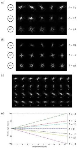
FIG. 3. (a) Measured intensity distributions of three selected OAM beams at different heater powers (0 mW, 5.37 mW, 10.74 mW, 16.1 mW
[image:5.612.173.442.177.684.2]6
and 2π), (c) Rotation of the interference pattern (𝒍 = ±𝟏) with various phase shifts between two OAM beams, (d) Rotation angles of various topological charges with the increasing applied power on the resistive heater.
Fig. 3(a) displays the rotating trend under different voltages with the interference pattern of𝑙 = ∓1,𝑙 = ∓2and𝑙 = ±3
modes at five applied voltages, which is in very good agreement with numerical simulations shown in Fig. 3(b). It can be
seen that under the same applied voltage, the petal pattern formed by mode pairs of different |𝑙|rotate at different rates (𝜋/
|𝑙|) and those with different signs (± or ∓) have different direction of rotation. In all of three OAM states, the rotating petal
patterns stay same shape, indicating that the OAM states do not change. Fig. 3(c) displays the rotating pattern of mode
𝑙 = ±1 with 32 samples. With the increasing electrical power (0-20.8mW), the image gradually rotates 180° while the pattern
shape does not change. In Fig. 2(b), Fig. 3(a) and Fig. 3(c), the interference patterns form a set of spots. This is because the
wavefront of the two OAM beams have the same curvature, in which case their Gouy-phase shifts tend to be zero so the
interference pattern looks like 2|𝑙| intense spots of light18. According to Eqs. (1)-(5), it should be note that a radiated OAM
beam with topological charge of𝑙 from the ring resonator can be decomposed into the superposition of two OAM beams with
topological charges of𝑙 + 1 and 𝑙 − 1, respectively. Therefore, only in the petal patterns of 𝑙 = ∓1 and𝑙 = ±1, there is a
bright spot at the center indicating the J0 component.
A plot of rotation angle for different optical vortex pairs against dissipated power is shown in Fig. 3(d). The experimental results show that
the rotation angles, and therefore the phase shifts, have linear relationships with the dissipated power, at different slopes depending on the
value of 𝑙and the wavelength detuning. The 𝑙 = 0mode does not rotate. For others, the rotation is more pronounced in lower order mode
beams. At the power of 20.8mW, 𝑙 = ∓1and 𝑙 = ∓2and 𝑙 = ∓3 modes rotate 180°, 90° and 60° clockwise, respectively. On the other
hand, 𝑙 = ±1, 𝑙 = ±2and𝑙 = ±3modes rotate 180° , 90° and 60° counter-clockwise, respectively. It can be seen that the slopes of the
rotation rate are proportional to𝜋/|𝑙|, which agrees with the cosinusoidally-varying intensitycos(2𝑙𝜑 − 𝜃) in Eq. (5).
On-chip electrical modulation of relative phase between pairs of OAM beams with opposite signs has been demonstrated using a silicon
photonic PIC. The experiment results show that changing the relative phase between the two collinear OAM beams leads to the rotation of
the interference pattern. The phase shift is linearly proportional to applied electrical power, and the rotating angles are shown to be
inversely proportional to topological charge with the same power. This is the first demonstration of generating OAM beams with
superposition states and controlling the phase between two OAM modes on an integrated silicon device. In the future, this scheme can be
intentionally implemented with other modulation elements to achieve more complicated applications. For example, a thermo-optical
resistive heater can be connected with the ring cavity to actively switch emitted OAM mode of the superposition states14. Also, if a
7
OAM modes, but also their amplitudes. The scheme can be applied to lab-on-chip, optical trapping19,20, sensing21,22, and communications
functions involving OAM modes.
REFERENCES
1. Poynting, J. H. The Wave Motion of a Revolving Shaft, and a Suggestion as to the Angular Momentum in a Beam of Circularly Polarised Light. Proc. R. Soc. A Math. Phys. Eng. Sci.82, 560–567 (1909).
2. Allen, L., Beijersbergen, M., Spreeuw, R. & Woerdman, J. Orbital angular momentum of light and the transformation of Laguerre-Gaussian laser modes. Physical Review A45, 8185–8189 (1992).
3. Kotlyar, V. V et al. Generation of phase singularity through diffracting a plane or Gaussian beam by a spiral phase plate. J. Opt. Soc. Am. A. Opt. Image Sci. Vis.22, 849–61 (2005).
4. Bazhenov, V. Y., Vasnetsov, M. V & Soskin, M. S. Laser beams with screw dislocations in their wavefronts.
Jetp Lett52, 429–431 (1990).
5. Heckenberg, N. R., McDuff, R., Smith, C. P. & White, A. G. Generation of optical phase singularities by computer-generated holograms. Opt. Lett.17, 221 (1992).
6. Beijersbergen, M. W., Allen, L., van der Veen, H. E. L. O. & Woerdman, J. P. Astigmatic laser mode converters and transfer of orbital angular momentum. Opt. Commun.96, 123–132 (1993).
7. González, N., Molina-Terriza, G. & Torres, J. P. How a Dove prism transforms the orbital angular momentum of a light beam. Opt. Express14, 9093 (2006).
8. Biener, G., Niv, A., Kleiner, V. & Hasman, E. Formation of helical beams by use of Pancharatnam-Berry phase optical elements. Opt. Lett.27, 1875 (2002).
9. Yu, N. et al. Light propagation with phase discontinuities: generalized laws of reflection and refraction.
Science334, 333–7 (2011).
10. Curtis, J. E. & Grier, D. G. Modulated optical vortices. Opt. Lett.28, 872–4 (2003).
11. Wang, J. et al. Terabit free-space data transmission employing orbital angular momentum multiplexing.
Nat. Photonics6, (2012).
12. Schmitz, C. H. J., Uhrig, K., Spatz, J. P. & Curtis, J. E. Tuning the orbital angular momentum in optical vortex beams. Opt. Express14, 6604 (2006).
13. Franke-Arnold, S. et al. Optical ferris wheel for ultracold atoms. Opt. Express15, 8619–25 (2007).
14. Strain, M. J. et al. Fast electrical switching of orbital angular momentum modes using ultra-compact integrated vortex emitters. Nat. Commun.5, 4856 (2014).
15. Zhu, J., Cai, X., Chen, Y. & Yu, S. Theoretical model for angular grating-based integrated optical vortex beam emitters. Opt. Lett.38, 1343–5 (2013).
16. Zhu, J., Chen, Y., Zhang, Y., Cai, X. & Yu, S. Spin and orbital angular momentum and their conversion in cylindrical vector vortices. Opt. Lett.39, 4435–8 (2014).
17. Cai, X. et al. Integrated compact optical vortex beam emitters. Science338, 363–6 (2012).
18. Macdonald, M. P., Paterson, L., Arlt, J., Sibbett, W. & Dholakia, K. Revolving interference patterns for the rotation of optically trapped particles. 201, 21–28 (2002).
19. Melville, H. et al. Optical trapping of three-dimensional structures using dynamic holograms. Opt. Express
11, 3562 (2003).
20. Jesacher, A., Fürhapter, S., Bernet, S. & Ritsch-Marte, M. Size selective trapping with optical ‘cogwheel’ tweezers. Opt. Express12, 4129–4135 (2004).
21. Lavery, M. P. J., Speirits, F. C., Barnett, S. M. & Padgett, M. J. Detection of a spinning object using light’s orbital angular momentum. Science341, 537–40 (2013).
22. Phillips, D. B. et al. Rotational Doppler velocimetry to probe the angular velocity of spinning microparticles.