Code Design for MIMO Broadcast Channels
Momin Uppal,
Student Member, IEEE
, Vladimir Stankovi´c,
Member, IEEE
, and Zixiang Xiong
Fellow, IEEE
Abstract—Recent information-theoretic results show the
opti-mality of dirty-paper coding (DPC) in achieving the full capacity region of the Gaussian multiple-input multiple-output (MIMO) broadcast channel (BC). This paper presents a DPC based code design for BCs. We consider the case in which there is an individual rate/signal-to-interference-plus-noise ratio (SINR) constraint for each user. For afixed transmitter power, we choose the linear transmit precoding matrix such that the SINRs at users are uniformly maximized, thus ensuring the best bit-error rate performance. We start with Cover’s simplest two-user Gaussian BC and present a coding scheme that operates 1.44 dB from the boundary of the capacity region at the rate of one bit per real sample (b/s) for each user. We then extend the coding strategy to a two-user MIMO Gaussian BC with two transmit antennas at the base-station and develop thefirst limit-approaching code design using nested turbo codes for DPC. At the rate of 1 b/s for each user, our design operates 1.48 dB from the capacity region boundary. We also consider the performance of our scheme over a slow fading BC. For two transmit antennas, simulation results indicate a performance loss of only 1.4 dB, 1.64 dB and 1.99 dB from the theoretical limit in terms of the total transmission power for the two, three and four user case, respectively.
Index Terms—Dirty-paper coding, MIMO broadcast channels,
multiple access channel, nested turbo codes, zero-forcing linear beamforming.
I. INTRODUCTION
A
N achievable rate region of a degraded Gaussian broad-cast channel (BC), where different users receive signals at different signal-to-interference-plus-noise ratios (SINRs), was provided by Cover in 1972 [1]. The scheme is based on superposition coding, where the message for one user is embedded in that for the other. Bergman [2] showed that Cover’s rate region is in fact the capacity region by proving the converse. However, the capacity region of the Gaussian multiple-input multiple-output (MIMO) BC, where the channels might not necessarily be degraded, was an open problem until recently−the rate region found in [3] wasfirst shown to achieve the sum-rate capacity in [3]–[6] and then proven to be the actual capacity region in [7].The core of the capacity-achieving scheme [3] for a Gaus-sian MIMO BC is a non-linear technique called dirty-paper coding (DPC) [8], which is a coding technique for channels
Paper approved by I. Lee, the Editor for Wireless Communication Theory of the IEEE Communications Society. Manuscript received July 1, 2007; revised December 4, 2007.
M. Uppal and Z. Xiong are with the Dept of Electrical and Computer Engineering, Texas A&M University, College Station, TX 77843 (e-mail: {momin, zx}@ece.tamu.edu).
V. Stankovi´c was with the Dept of Electrical and Computer Engineer-ing, Texas A&M University. He is now with the Dept of Electronic and Electrical Engineering, University of Strathclyde, Glasgow, UK (e-mail: [email protected]).
Work supported by NSF grant CCF-0729149 and Qatar National Research Fund NPRP 28-6-7-28.
Digital Object Identifier 10.1109/TCOMM.2009.04.070300
with encoder side information. According to [8], in a Gaussian interference channel, if the interfering signal is known non-causally at the transmitter, then there is no loss in capacity due to the interference. This scenario is typical in the Gaussian BC, where each user treats messages intended for other users as interference, which is available non-causally at the transmitter. DPC is the only optimal, i.e., capacity-achieving, technique for the non-degraded Gaussian MIMO BC. It provides signif-icant gains in terms of the achievable rates over suboptimal techniques (e.g., time-division multiple-access and beamform-ing) for the MIMO BC in many setups [3], [9], especially when the signal-to-noise ratio (SNR) is high and the number of transmit antennas large. Practical DPC involves both source and channel coding [10], and near-capacity code designs have appeared recently [11]–[14]. The time is thus ripe to develop limit approaching DPC-based code designs1for the MIMO BC
and compare them with others based on suboptimal strategies. We start with Cover’s simplest yet most celebrated two-user degraded Gaussian BC [1] and develop a code design that employs the dirty-paper code of [11] using nested turbo codes. Owing to the powerful nested turbo codes in DPC, our code design for the degraded Gaussian BC is superior to previously reported DPC-based schemes of [17], [18] and loses only 1.44 dB from the boundary of the capacity region when transmitting one bit per real sample (b/s) for each user. Note that, besides DPC, superposition coding [1] also achieves the capacity of this simple Gaussian BC. The practi-cal scheme of [19] that exploits superposition coding performs only 1.0 dB from the minimum total power at one b/s for each user. However, the drawback of the superposition coding approach of [19] is that it is not clear how it can be extended to handle the MIMO Gaussian BC, where the channels are not necessarily degraded. In contrast to superposition coding, DPC achieves the capacity of both degraded and non-degraded BCs, and our DPC-based design for Cover’s Gaussian BC naturally applies to the MIMO BC. Thus, we additionally consider the two-user MIMO Gaussian BC with two transmit antennas at the base-station and develop thefirst limit-approaching DPC-based code design under the assumption that the transmitter and all the receivers have perfect knowledge of the channel state information (CSI). We point out that in practice, the CSI might not be perfectly available at the transmitters. However, as the first step towards developing DPC-based code design for MIMO broadcast channels, we make such a rather strong assumption in this paper. Extending our design to the case with imperfect/partial CSI at the transmitter is the next step, which we leave to future publications.
1To the best of our knowledge, all existing DPC-based designs [15], [16]
for the MIMO BC use scalar forms of DPC such as Tomlinson-Harashima precoding and hence incur a large performance loss.
Most information-theoretic works [3]–[6] on MIMO BCs focus on maximizing the sum-rate, i.e., the sum of the trans-mission rates for different users under afixed total transmis-sion power constraint. This allows arbitrary rate allocation to different users depending on the channel coefficients. The sum-rate maximizing scheme in this case might result in an unfair rate allocation (e.g., by assigning a very low rate to one user). However, many applications require the users to operate at a certain minimum rate/SINR. In addition, our DPC code design with nested turbo codes [11] operates at afixed transmission rate. In light of these two reasons, wefix the rate of the employed code at each user. Thus, our coding scheme has the design objective of uniformly maximizing the SINR for each user, subject to a total transmit power constraint and certain per user rate/SINR constraints. Compared to the sum-rate maximizing scheme, our scheme will obviously achieve a smaller or equal sum-rate. To determine a precoding scheme at the transmitter that uniformly maximizes the individual rate/SINR at each user, one can invoke the duality [4], [5], [20] between the BC and the multiple access channel (MAC); as shown in [21], optimal precoding can be accomplished with reasonable computational complexity by employing an iterative procedure at the encoder.
We employ one conventional channel code for the first user and one dirty-paper code for each of the remaining users for coding over MIMO Gaussian BC. Experiments show that our design for two users and two transmit antennas operates 1.48 dB from the capacity region boundary. We also simulate sub-optimal strategies such as zero-forcing DPC (ZFDPC) and zero-forcing beamforming (ZFBF). However, the performance gap between the optimal strategy and the zero-forcing approaches depend on the exact realization of the channel coefficients. Thus, in order to provide a fair comparison, we also consider the outage performance of our design over a slow Rayleigh fading MIMO BC. Simulations indicate that when the number of transmit antennas is fixed at two, our practical DPC-based design performs 1.4 dB, 1.64 dB and 1.99 dB worse than the theoretical limits for the two, three and four user case, respectively. Preliminary results of this work appeared in [22].
The contributions of this paper are twofold: our DPC-based design for Cover’s celebrated two-user degraded Gaussian BC significantly outperforms existing schemes [17], [18], and is the only scheme in the literature that beats the time-sharing line (see Fig. 4); we also develop the first limit approaching code design for the MIMO Gaussian BC using the powerful turbo-based DPC scheme of [11].
Finally, we point out that recent dirty-paper code designs [12]–[14] based on vector quantizers and LDPC/irregular repeat accumulate codes work very well at the low rate regime (e.g., at 0.25 b/s). However, it is not easy to redesign them (e.g., the best performing one [14] in this class) to operate well at high transmission rates for broadcast applications.
II. CHANNEL CAPACITIES
In this section, we give a brief overview of the capacity regions for the two-user degraded Gaussian BC [1] and the MIMO Gaussian BC [3].
Traditional Channel Coding
Dirty-paper Coding
w1
w2
1
2 1
h h
ρ ρ
− x
x
x (1−ρ)Pt
t
P ρ
+
User 2 User 1
Transmitter side information
U1
U2
X
h1
h2
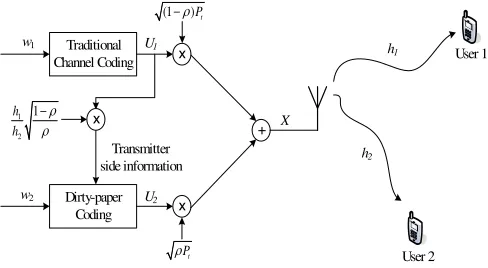
Fig. 1. Encoding setup for the two user degraded Gaussian BC.
A. Two-user degraded Gaussian BC
Consider a two-user Gaussian BC with a single-antenna transmitter which sends signalX; the two users receiveY1= h1X+Z1andY2=h2X+Z2, whereZ1andZ2are indepen-dent, identically distributed (i.i.d.) zero-mean Gaussian noises with unit variances, independent ofX, andh1,h2are constant channel coefficients. Since the channel is degraded, without loss of generality, we assume that|h2|>|h1|. The transmitted signalX is given byX=B[U1, U2]T, whereU
1 andU2 are
the coded messages intended for user 1 and 2, respectively, with E[|U1|2], E[|U2|2] ≤1; B = [(1−ρ)P ,√ρP] is the
precoding matrix, with P being the total transmission power constraint, i.e.,E[|X|2]≤P, andρ(0≤ρ≤1)a parameter
that controls the power allocation between the two users. Cover [1] obtained the capacity region for this setup by using superposition coding. However, DPC also achieves all points in the capacity region. Indeed, U2 can be dirty-paper coded withU1 as the encoder side information as shown in Fig. 1. This way, user 2 achieves the same rate as if the interference fromU1were not present. User 1 on the other hand, treatsU2 as interference. Then the achievable rates per real dimension R1 andR2 for user 1 and user 2, respectively, are
R1≤ 12log
1 +|h1|2(1−ρ)P
|h1|2ρP + 1
(1)
and
R2≤12log1 +|h2|2ρP. (2)
Since user 1 always gets a degraded version of the signal received by user 2, user 2 can also decodeU1, provided that it knows the codebook of user 1. Then, the effective achievable rate for user 2 is R1+R2.
B. Non-degraded MIMO BC
[image:2.585.315.559.45.179.2]useri,Xj is the complex baseband equivalent of the transmit-ted signal at antennaj, and the Zi’s are i.i.d. complex zero-mean Gaussian noises with unit variances, independent of the Xj’s. Let Y= [Y1, Y2, . . . , YK]T, X= [X1, X2, . . . , XM]T, andZ= [Z1, Z2, . . . , ZK]T; then the received vector becomes
Y=HX+Z, withhij corresponding to the element at the ithrow andjth column of theK×M channel matrixH.
Let wi be the message intended for user i, then the transmitter sendsX=BU, whereBis anM×K precoding matrix, and
U = [U1, U2, U3, . . . , UK]T
= [U1(w1), U2(w2;U1), . . . , UK(wK;U1, . . . , UK−1)]T
is generated using successive DPC with all K codebooks being uncorrelated and Gaussian with unit power. Here,Ui= Ui(wi;U1, . . . , Ui−1),2≤i≤K, indicates thatwiis encoded as the codewordUiusing DPC with the linear combination of U1, U2, . . . , Ui−1as the encoder side information (i.e., known
interference).
Let bi be theithcolumn of the precoding matrix B, then the M ×M transmitter covariance matrix for each user is a positive semi-definite matrix given bySi=bibHi , and the transmitter power constraint isKi=1tr(Si)≤P. We can now write the signal received at useri as
Yi=hi i−1
k=1
bkUk+hibiUi+hi K
k=i+1
bkUk+Zi, (3)
where hi represents the ith row of the channel matrix H. Due to DPC, userican cancel out thefirst term, whereas the second term is the useful signal, and the third is treated as Gaussian interference. Therefore, the achievable rateRBC
i at
userisatisfies [6]
RBC
i ≤
1
2log 1 +
hiSihHi 1 +hiKk=i+1SkhHi
, i= 1, . . . , K.
(4) Note that the rate vector RBC = [RBC
1 , . . . , RBCK ] is achievable under afixed encoding order, where the message of useriis dirty-paper coded by treating signals for previously encoded users as known interference. One can therefore obtain K! different achievable rate vectors, one for each distinct encoding order. The capacity region of the MIMO BC for a fixed channel matrixHand a power constraintPis the convex hull of the union of all rate vectors obtained over all possible encoding orders and all covariance matricesSi satisfying the power constraintKi=1tr(Si)≤P.
C. Duality between the Gaussian BC and MAC
The duality between the capacity regions of the Gaussian MIMO BC and MAC was pointed out in [4], [5]. Unlike the achievable rates for the MIMO BC, given by (4), the rates for the MAC are concave functions of the input covariances. Therefore, it is easier to find the boundary of the capacity region of the MAC than that of the BC. By exploiting the duality [4], [5], the achievable rates for the MIMO BC can be derived from those of its dual MAC. Here we briefly review this duality principle which will be used in Section III to determine optimal precoding.
The dual MAC of the MIMO BC described in Section II-B has K users, each with a single antenna transmitting messages simultaneously over Gaussian channels to a single receiver with M receive antennas. If user i transmits signal
Ui, the sum of the individual transmission powers satisfies the
same power constraint as that of the BC, i.e., Ki=1ξi ≤P, where ξi =E[|Ui2|]. The decoding order of the MAC is the reverse of the encoding order for the dual MIMO BC, i.e., the signals of users i+ 1(1 ≤i < K) throughK are treated as perfectly known, and the rest is unknown interference. Then, the achievable rate for useri is [23]
RMAC
i ≤
1 2log
|IM +ik=1ξkhHkhk|
|IM +ki−=11 ξkhHkhk|
. (5)
According to [4], a transformation which depends on the channel matrix and the noise statistics can be defined to map the set of MAC powers{ξi} to the BC transmitter covariance matrices {Si} and hence {bi}, and vice versa. Moreover, the sets of achievable rates are equal in both domains, i.e.,
RMAC
i =RBCi .
III. OPTIMAL PRECODING UNDER INDIVIDUAL RATE CONSTRAINTS
A code design for MIMO BC requiresfinding an appropri-ate precoding matrixB. Previous information-theoretic works [3]–[6] have mainly focused on evaluatingBto maximize the achievable sum-rate, in which case the encoder and decoder for each user must be able to operate at an arbitrary code rate. However, as mentioned earlier, such a scheme might result in an unfair rate allocation. Also it is not clear how to design good dirty-paper codes at different rates on the fly. Therefore, we consider a scenario in which each user is assumed to operate at a fixed transmission rate, for which we already have an efficient dirty-paper code design [11]. Note that this strategy, as opposed to the sum-rate maximizing scheme, cannot optimally allocate rates to the user, and thus for the same sum-rate the former will suffer a performance loss compared to the latter, as indicated in Section VI.
Let Ri be the rate of the practical channel code (fori = 1) and the dirty-paper code (for 2 ≤ i ≤ K). We assume that there is a minimum bit-error rate (BER) requirement at each user, which translates into a minimum requirement on the operating SINR. Let the rate-Ri code performδidB away from the corresponding Shannon limit of10 log10(22Ri−1)dB at the given minimum BER. Then, in order to satisfy the BER requirement, its operating SINR ηi = hibib
H i hHi
1+hiKk=i+1bkbHkhHi must satisfy
ηi≥ηio= 10 log10(22Ri−1) +δi dB. (6)
For example, the dirty-paper code [11] we use in this work performs δi = 1.53 dB away from the Shannon limit at Ri= 1.0b/s and a BER of10−5. Since there is a one-to-one correspondence between the rateRi of the practical code and its minimum operating SINR ηo
i given by (6), in the sequel, we exclusively speak of the SINR constraints instead of the rate constraints.
in order to get the best BER performance, we uniformly maximize the SINR at each user. Specifically, we consider the following optimization problem:
max
B β (7)
such that
hibibHi hHi 1 +hiKk=i+1bkbHk hHi
≥βηo
i, i= 1, . . . , K
and
E[uHBHBu]≤P,
where the first K constraints correspond to the SINR re-quirements and the last one defines the transmitter power constraint. For the sake of simplicity, we describe the solution to this optimization procedure for a fixed encoding order. A search for an encoding order that results in the largest β is then needed. Such an encoding order can be found by using the iterative algorithm of [15]. In the following, we discuss optimal precoding for the case of a degraded Gaussian BC [1] before moving on to the case of MIMO BC.
A. Precoding for two-user degraded Gaussian BC
The problem here is tofind a precoding matrixBthat solves the optimization problem of (7). Recall from Section II-A that for a given transmit powerP, the precoding matrix is given by B = [(1−ρ)P ,√ρP]. Thus, the objective is to find the power allocation parameterρwhich maximizesβ. It can be shown thatβ is maximized when the SINR constraints and the power constraint in (7) are all met with equality. Thus, the optimumρ∗ andβ∗ can be obtained by solving the equations η1=|h1|2(1−ρ)P
|h1|2ρP+1 =βη
o
1 andη2=|h2|2ρP =βη2o, yielding
ρ∗=−
ηo
1
|h1|2 +
ηo
2
|h2|2
+( ηo1
|h1|2 +
ηo
2
|h2|2)2+ 4
ηo
1ηo2P
|h2|2
2ηo
1P
(8)
and
β∗ =ρ∗P|h2|2
η0 2
. (9)
B. Precoding for MIMO BC
In this subsection, we first present an iterative approach to solving (7), we then discuss some sub-optimal choices of the precoding matrixB.
1) Optimal precoding: The SINR constraints in (7) in the case of MIMO BC are not convex. In order to simplify the problem, we can invoke duality between BC and MAC. As a result, the problem (7) is equivalent to the following MAC domain problem:
max
{ξi}
β (10)
such that
ξihi(I+ i−1
j=1
ξihHj hj)−1hHi ≥βηio, i= 1, . . . , K and
K
k=1
ξk ≤P.
The optimal choice of {ξi} results in the SINR constraints and the power constraint being met with equality. Thus, the optimalβ∗and{ξ∗
i}are solutions to the equations obtained by replacing theK+1inequalities in (10) by equalities. However, obtaining a closed form solution to this problem is not easy. We thus consider an alternative approach which involves solving the converse problem of (10), i.e., the problem of finding the minimum transmitter power such that the minimum SINR constraints of βηo
i are satisfied (here β is assumed to be a constant). This converse problem can be stated as
min
{ξi} K
k=1
ξk (11)
such that
ξihi(I+ i−1
j=1
ξihHj hj)−1hHi ≥βηoi, i= 1, . . . , K.
The solution to this converse problem also requires the SINR constraints to be met with equality and can easily be obtained by following the procedure in [15], [21]. It is obvious that if the transmitter power in (10) is equal to the optimum objective function valueP∗of (11), the optimumβ∗obtained by solving (10) would the same as theβ used in (11). In addition,P∗is a monotonically increasing function ofβ. Thus, the solution to (10) can be obtained from the following iterative procedure:
1: Select initialβmin andβmax.
2: β := (βmin+βmax)/2.
3: Solve (11) using procedure in [15], [21] to obtain{ξ∗ i}. EvaluateP∗=K
k=1ξk∗.
4: IfP∗> P,βmax=β Else IfP∗< P,βmin=β.
5: If|P−P∗| ≥Goto step 2 Else End.
One can then apply the MAC-to-BC transformation of [4] to obtain the optimal precoding matrixB.
2) Zero-forcing: We briefly mention the two suboptimal approaches considered in [3], namely, zero-forcing DPC (ZFDPC) and zero-forcing beamforming (ZFBF) [24]. As the name zero-forcing suggests, the choice of the precoding matrix forces the interference at each user to be zero, and hence induces K non-interfering channels between the transmitter and the Kusers.
Let H =GK×KQK×M be the QR decomposition of the channel matrix obtained by Gram-Schmidt orthogonalization, whereGis a lower triangular matrix, i.e.,gij = 0 forj > i, andQsatisfiesQQH =I
K. As before,Mdenotes the number of transmitter antennas, and K is the number of users each with a single antenna. The precoding matrix is chosen asB=
QHR
K×K, whereRis adiagonalmatrix. This choice of B
introduces an additional equality constraint in the optimization problem (7) and ensures that at user i the interference from all usersj > i is forced to zero. With the introduction of the equality constraint, (7) is equivalent to
max
{|rii|}
β (12)
such that
and
K
k=1
|rii|2≤P,
the solution to which can be easily obtained as|r∗ ii|2= β
∗ηo i
|gii|2 withβ∗=PK
k=1|gii|
2
ηo i .
On the other hand, in ZFBF, the precoding matrix is chosen asB=H†R, whereH† is the pseudo inverse of the channel matrix H and R is again a diagonal matrix. The received signal vector in this case isY=HBU+Z=RU+Z. Thus, the interfering signals from all users are forced to zero, which simplifies the code design since DPC is no longer required. In this case, one needs to solve the following problem:
max
{|rii|}β (13)
such that
|rii|2≥βηio, i= 1, . . . , K and
M
j=1
K
k=1
|h†jkrkk|2≤P.
The solution to the ZFBF problem can be obtained as|r∗ ii|2= β∗ηo
i withβ∗ =M P
j=1Kk=1|h†jk|2ηio
(1≤i≤K).
Although zero-forcing is near optimal when the sum-rate is maximized [3], simulations (see Section VI) show that when considering outage performance in a fading environment, it is far from optimum in the setup with individual rate constraints. One disadvantage of zero-forcing is that under individual rate constraints, it fails when there are more users than the total number of transmit antennas, i.e., the solution to the optimization problems (12) and (13) always yields β∗ = 0
when M < K. This problem was recently addressed in
[25], where different suboptimal solutions based on partial interference cancellation are proposed.
IV. DPCDESIGN BASED ON NESTED TURBO CODES
DPC [8] can be implemented using nested lattice codes [10], where the source code is nested within a channel code. Chouet al.[26], [27] reported a turbo-coded trellis-based construction for DPC by nesting a trellis coded quantization (TCQ) code inside a turbo-trellis coded modulation (TTCM). However, owing to the structural dissimilarity between TCQ and TTCM, the actual performance of TCQ is severely degraded and thus it affects the overall performance of the scheme, especially at low transmission rates. An improved design which alleviates the effect of this structural dissimilarity was proposed in [11] where a stronger source code referred to as theturbo-likeTCQ was employed. In order to provide a description of how the improved scheme of [11] works, we first briefly review the TCQ/TTCM scheme of [26], [27].
The trellis structure in the TCQ/TTCM scheme of [26], [27] is constructed via a rate-k/n/mconcatenated code (denoted by C1+C2, with C1being the rate-k
nconvolutional code and C2 being the rate-n
m convolutional code) as shown in the encoder block diagram in Fig. 2 (a). TCQ essentially relies on the trellis Γ1 formed by C1+C2; the TTCM code consists of a parallel concatenated code with C2in both branches. C2in the
C2
V
α
x
Channel Code (TTCM )
Π Π−1
+
H-1
C1
PA M I
k bits
n bits
n-k bits
m bits
+
Ra te kn
C2 Ra te mn
Rate nm
U
Source Code ( TC Q)Rate k
m
w
(a)
Hard Decision S I
1 (C1 C )2
Γ +
k bits
Channel Code (TTCM)
PAM + C2
C2
m bits
H-1 n bits
n-k bits
Π Π
1 −
Π
1 −
Π
a priori info from Trellis Γ2 (C )2
I
Source Code ( Turbo-like TCQ)Rate mk V
α x U
w
(b)
Fig. 2. Block diagram of (a) the TCQ/TTCM encoder of [26], [27] and (b) the turbo-like TCQ/TTCM encoder of [11].
bottom branch is preceded by ann-bit symbol interleaver and followed by anm-bit symbol deinterleaver. The two branches are multiplexed by taking even/odd-indexed symbols from the top/bottom branch before PAM.
At the encoder, every (n−k)-bit segment of the message wis mapped to ann-bit symbol by the pseudo inverse of the parity-check matrixH of C1 before being added to an output n-bit symbol of C1. This way, the codewords of C1+C2 are shifted by a fixed amount as determined by the message w. Consequently, one coset of TTCM codewords is selected byw to be used for TCQ, which uses the Viterbi algorithm to search for its input sequence ofk-bit symbols so that the scaled side information sequenceαV is quantized to an output sequence x. The quantization error sequence U = x−αV is finally transmitted. At the decoder, then-bit input symbols to TTCM (or codewords of C1) are recovered by an iterative BCJR decoder. Finally, the transmitted message w is reconstructed by calculating the syndromes of the recovered codewords of C1.
Whereas the presence of an interleaver in Fig. 2 (a) greatly boosts the performance of the TTCM code over TCM, the TCQ source code suffers because the interleaver significantly increases the number of paths that need to be searched, making the Viterbi algorithm no longer a viable solution to finding the closest codeword x to αV. In [26], [27], the bottom branch of TTCM is simply ignored during TCQ. But the actual average quantization error E[U2]includes contributions from
both even-indexed symbols from the top branch and odd-indexed symbols from the bottom branch. This leads to an extra quantization error inE[U2]that is responsible for the
[image:5.585.313.564.43.325.2]In order to reduce this extra quantization error, a nested turbo code design was proposed in [11] to take into account the bottom branch of TTCM in source coding. The encoder block diagram of that code design is depicted in Fig. 2 (b), where the obvious difference from Fig. 2 (a) is the employment of a new turbo-like TCQ in place of TCQ. The main difference between turbo-like TCQ and TCQ lies in the computation of the input sequences of symbolsI= [I(0), . . . , I(L−1)]to the TTCM encoder. This sequence is evaluated using a soft-output Viterbi algorithm, which adopts a composite distortion metric to take both branches into account. This distortion metric is the same as the TCQ metric for the even positions on the top branch of TTCM, whereas the distortion for the odd positions on the bottom branch of TTCM is provided by the trellisΓ2 in the form ofa-prioriinformation.
The source coding component of Fig. 2 (b) is referred to as turbo-like TCQ because it has a parallel concatenated structure with interleaversΠandΠ−1, and more importantly,
it essentially implements the first iteration of turbo TCQ, which takes advantage of the fact [28] that turbo TCQ gen-erally improves upon TCQ at thefirst iteration before losing ground at subsequent iterations. Without iterative quantization (or source encoding), the distortion from the bottom branch of TTCM can only be included in the form ofa priori informa-tion. This limits the improvement of turbo-like TCQ/TTCM over TCQ/TTCM in terms of source coding performance. To alleviate the impact of the inaccuratea-prioriinformation from the bottom branch, another novelty in the code design of [11] lies in decreasing the percentage of samples processed by that branch and picking the optimal percentage for best DPC performance.
Results in [11] indicate that nested turbo coding performs significantly better than the scheme of [26], [27] at all transmission rates. For example, at 1.0 b/s, nested turbo coding performs 1.53 dB away from capacity. In contrast, the TCQ/TTCM scheme of [26], [27] shows a gap of 2.07 dB from capacity.
V. OVERALLCODE DESIGN FORMIMO BC
[image:6.585.315.560.43.219.2]In this section, we describe the practical coding strategy for the MIMO BC using the capacity approaching DPC design of Section IV. According to the capacity achieving scheme described in Section II-B, user 1 does not have any side information. Thus, user 1 should employ a traditional channel code. For our code design we use conventional TTCM and a PAM constellation for user 1. The remaining users exploit the turbo-like TCQ/TTCM scheme for DPC. We thus require one conventional channel code andK−1 dirty-paper codes. Our overall DPC-based code design is schematically shown in Fig. 3. This design is applicable to both the degraded Gaussian BC and the MIMO Gaussian BC. In the following, we discuss several issues in applying the turbo-like TCQ/TTCM scheme to code design for the MIMO BC.
1. Normalization at the receiver: The complex baseband equivalent of the received signal at user i is given by (3). In order for useri to decode its message correctly, the user needs to work with the same constellation as was used at the encoder for Xi. For this purpose, as indicated in Fig. 3 we
User K
User i
User 1
Channel Transmitter
TTCM Encoder w1
U1
Ui
DPC Encoder
wi
DPC Encoder
wK
UK
Precoding
B = [b1,…, bK]
Y1 '
x
1 1
1 h b
+
TTCM Decoder
wi'
x 1
ii h b
DPC Decoder Yi
'
x 1
KK h b
DPC Decoder YK' wK'
w1'
X1
XM
h1 +
Z1
hi
Zi
+
hK
ZK X
Vi
[image:6.585.331.555.311.397.2]VK
Fig. 3. Block diagram of our proposed overall DPC-based coding scheme for MIMO BC.
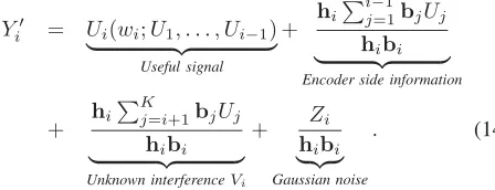
normalize the received signal at useribyhibi. It is apparent that this normalization does not affect the received SINR. The resulting signal can be written as
Y
i = Ui(wi;U1, . . . , Ui−1) Useful signal
+ hi
i−1
j=1bjUj
hibi
Encoder side information
+ hi
K
j=i+1bjUj
hibi
Unknown interferenceVi
+ Zi
hibi
Gaussian noise
. (14)
Hence, the side information term in Fig. 3 for theith (i >1) user is given by Vi =hi
i−1
j=1bjUj
hibi .
2. Extension to complex baseband: The theoretical back-ground in the earlier sections assumes the baseband equivalent of the coded messagesUito be complex numbers. In practice this can be realized by using a two dimensional constellation such as QAM. However, note that the coded message in the DPC scheme of Fig. 2 (b) is mapped to a PAM constellation, indicating that the baseband equivalent of the signals are real. In order to get a complex output, we combine the outputs of two independent nested turbo codes (denoted by UI and UQ), in which the phase of UQ is shifted by 90 degrees via multiplication by j = √−1. If V is a complex side information at the encoder, the side information inputs to the two encoders are VI = Re{V} and VQ = Im{V}. At the decoder, the real part of the received signal YI can be tied to the input of one DPC decoder, while the imaginary part YQ to another independent decoder. This way we effectively convert the PAM constellation of our DPC scheme to a QAM constellation. Note that the same principle can also be applied to the TTCM code of user 1.
the individual users. Even with this feedback, the CSI is not guaranteed to be available perfectly at the transmitter. However, as mentioned earlier, for our designs we assume that the CSI is available at the encoder perfectly before the transmission begins. We will leave the case of imperfect CSI at the transmitter as a possible extension to this work.
4. Non-Gaussian interference:As indicated in Section IV, the codewords of the convolutional code C2 are mapped to a PAM constellation. This results in an interference at the decoders which is not Gaussian. The practical decoders should thus be designed to exploit the non-Gaussian statistics of the interference. This would require them computing the channel likelihood values based on the actual noise plus interference distribution. However, this computation becomes cumbersome, especially for a large number of interferers and/or a large constellation size. For the sake of simplicity, our implemented decoders assume that the noise plus interference is Gaussian with variance equal to that of the actual distribution. Because of this assumption, our decoders suffer a performance loss from the case which exploits the non-Gaussian statistics. Fortunately, simulations (not included in this paper) indicate that this performance loss is not significant. Similarly, the side informationVi in (14) will not be Gaussian, but Costa’s capacity result [8] holds also for arbitrary side information [29]. Our simulations with the dirty-paper code construction of Section IV verify this.
VI. SIMULATION RESULTS
In our code design, we use a 16-state, rate-1
2 systematic
convolutional code for TTCM. The code polynomial is cho-sen as the constraint-length four Ungerboeck code for the PAM constellation (suboptimally to maximize the average Euclidean distance between TCM codewords). Specifically, the parity check polynomials for this code are h0(D) = 23 and h1(D) = 10 in octal notation. For the practical DPC scheme of Section IV, we choose C1 as a 16-state, rate-1
2,
non-systematic convolutional code with generator polynomials g0(D) = 23andg1(D) = 10. Code C2, on the other hand, is a 16-state, rate-2
3, systematic convolutional code with parity
check polynomialsh0(D) = 23,h1(D) = 10, andh2(D) = 0. The block length for both TTCM and dirty-paper code isfixed at10,000samples. In the following, wefirst present our simu-lation results for the two-user degraded Gaussian BC followed by results for MIMO Gaussian BC. The results for MIMO Gaussian BC include not only the performance of our nested turbo scheme with optimal precoding, but also with ZFDPC and ZFBF. However, as mentioned earlier, the performance gap between the three approaches depends greatly on what the exact realization of the channel coefficients is. Thus, in order to provide a fair comparison, we additionally consider the performance of these strategies over an ensemble of channel coefficients. Specifically, we analyze the performance based on an outage measure for the case of slow Rayleigh fading. All simulations are carried out at equal rates of 1 b/s for each user. This does not mean that our design only works for equal rate constraints, since the precoding strategies described in Section III are valid for any set of (including unequal) rate constraints. In addition, our DPC scheme based on nested turbo codes has been designed to work at rates of 0.5, 1.0 and 2.0 b/s in [11],
15 15.5 16 16.5 17 17.5 18
10−6
10−5 10−4 10−3 10−2 10−1
100
Transmitter Power (dB)
BER
1.44 dB
(a)
0 0.5 1 1.5 2 2.5 3
0 0.5 1 1.5
R1 + R2 (b/s)
R1 (b/s)
Capacity region boundary Time sharing line Rates with practical scheme
(b)
Fig. 4. (a) BER vs. the transmission powerPfor the degraded Gaussian BC, withR1 =R2 = 1b/s,h2= 1,h1 =√0.1. The dashed line represents
the capacity. (b) The capacity region for the degraded Gaussian BC with transmission powerP= 17.65dB,h2= 1, andh1=√0.1.
and can be modified to work at higher rates as well. The TTCM code can similarly be modified. In short, our schemes are readily applicable to the case with unequal rate constraints on the users.
A. Two-user degraded Gaussian BC
We simulate our DPC-based design for Cover’s two-user degraded Gaussian BC with channel coefficients h1 = √0.1 andh2= 1. Simulations indicate that at a rate of 1.0 b/s and a BER of10−5, the TTCM code for user 1 performsδ1= 0.98
dB, and the dirty-paper code at user 2 performsδ2= 1.53dB away from the Shannon limit. For a given transmit power, we evaluate the optimalρ∗from (8) and thus the optimal B, and plot the resulting BER averaged over the two users in Fig. 4 (a).
At a BER of 10−5, it is seen that the transmission power
[image:7.585.317.559.43.455.2]7 7.5 8 8.5 9 9.5 10 10.5 11 11.5 12 10−6
10−5 10−4 10−3 10−2 10−1 100
Transmitter Power (dB)
BER
Optimal Transform ZFDPC ZFBF Capacity
[image:8.585.54.297.42.219.2]1.48 dB 0.88 dB 1.18 dB
Fig. 5. BER vs. the transmission power for the two-user MIMO Gaussian BC with two transmit antennas,h1 = [1/√2e2.37j,√3/2e2.14j],h2 =
[e2.23j,0.5e0.87j]andR1=R2=1 b/s.
codes were used. This result is 1.8 dB better than that reported in [17]. Fig. 4 (b) depicts the capacity region forP = 17.65 dB, which is the required total power for our code design to operate at R1 = R2 = 1.0 b/s. Our operating point is significantly above the time-sharing line.
B. Non-degraded MIMO Gaussian BC
We also simulate our design for a two-user MIMO Gaussian BC with two transmit antennas at the base-station byfixing the channel coefficients as h1 = [1/√2e2.37j,√3/2e2.14j]
andh2 = [e2.23j,0.5e0.87j]. For a given transmit power, we
evaluate the optimum precoding matrix using the procedure outlined in Section III-B1. We plot the BER (averaged over the two users) versus the transmitter power curves in Fig. 5. It is seen that our practical code with optimal precoding performs only 1.48 dB away from the theoretical limit. Practical coding with ZFDPC performs 0.88 dB worse than with optimal precoding, while ZFBF loses an additional 1.18 dB.
C. Non-degraded MIMO fading BC
We assume the channels undergo independent Rayleigh slow flat fading, i.e., each element of the matrix His i.i.d., circularly symmetric, zero-mean, complex Gaussian with unit variance, andHis frame-wise constant. For a given realization of the channel coefficients H and a transmitter power con-straintP, we compute the maximumβ∗(H, P)(the arguments indicate that β∗ is a function of H and P) as described in Section III-B. Thus, the maximum achievable SINR at user i is β∗ηo
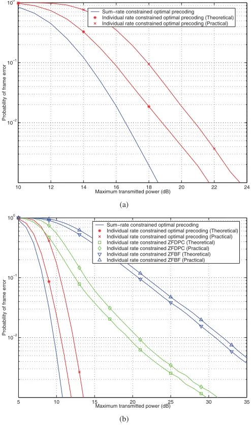
i. The actual BERs at each user will satisfy the minimum BER requirement if β∗ ≥ 1. In order to analyse the system performance, we consider the probability of frame error-like measurePfe(P) =P r(β∗(H, P)<1), where the probability is calculated by averaging over the ensemble of the channel matrixH. This probability can be thought of as the outage probability, where an outage event occurs whenever β∗(H, P)<1.Pfeis equivalent to the frame error probability if the frames at all users are received in error if and only if an outage event occurs. Note that this might not always be true,
5 10 15 20 25 30
10−2 10−1 100
Probability of frame error
Maximum transmitter power (dB) Sum−rate constrained optimal precoding
Individual rate constrained optimal precoding (Theoretical) Individual rate constrained optimal precoding (Practical) Individual rate constrained ZFDPC (Theoretical) Individual rate constrained ZFDPC (Practical) Individual rate constrained ZFBF (Theoretical) Individual rate constrained ZFBF (Practical)
(a)
5 10 15 20 25
10−3 10−2 10−1 100
Probability of frame error
Maximum transmitted power (dB) Sum−rate constrained optimal precoding
Individual rate constrained optimal precoding (Theoretical) Individual rate constrained optimal precoding (Practical)
(b)
Fig. 6. (a) Probability of frame error vs. maximum transmission powerPfor
K= 2andM= 2. (b) Probability of frame error vs. maximum transmission powerP forK= 3andM= 2.
nevertheless we still call this measure as the probability of frame error.
One can also evaluatePfe by using an alternative method which involves calculating the minimum required transmitter power P∗(H) such that the set of SINR requirements for
{ηi} in (6) are satisfied (P∗(H)can be obtained by solving (11)). Note that β∗ < 1 if and only if P∗(H) > P, and thus the probability of frame error can also be evaluated as Pfe(P) = P r(P∗(H) > P). We use this method of evaluating the probability of frame error when discussing our results. In the following, we evaluate the probability of frame error versus the transmitter power for the cases when the number of users or transmit antennas is up to four.
[image:8.585.314.560.46.467.2]in performance. 2.30 dB of this loss is due to the individual rate constraintsR1= 1.0andR2= 1.0b/s. Practical coding accounts for the remaining 1.40 dB loss. Compared to optimal DPC-based design, ZFDPC is approximately 6.50 dB worse while ZFBF loses an additional 5.50 dB.
2) Simulations for the three-user case: The results for three users and two transmit antennas are provided in Fig. 6 (b). Since in this case the number of transmit antennas is less than the number of users, zero-forcing (both ZFDPC and ZFBF) does not work. The sum-rate capacity curve is obtained by using the iterative waterfilling algorithm of [30]. Compared to this sum-rate capacity curve, our practical DPC-based code design loses 4.07 dB in performance. About 2.38 dB of this loss is due to the individual rates being constrained, while the remaining loss of 1.64 dB is due to practical coding.
With three transmit antennas, the loss due to the constraints on the individual rates reduces to 1.48 dB, while the practical coding loss is 1.58 dB. Simulation results show that our prac-tical DPC-based scheme with optimal precoding outperforms theoretical ZFDPC and ZFBF by 6.50 dB and 15.50 dB, respectively.
3) Simulations for the four-user case: The frame error rate (FER) versus the maximum transmission power curves for four users and two transmit antennas is provided in Fig. 7 (a); the loss due to individual rates being constrained is 2.25 dB while the practical coding loss is 1.99 dB.
In the case with three transmit antennas, the loss due the constraints on individual rates is 1.28 dB and the practical coding loss is 1.69 dB.
Fig. 7 (b) shows similar results for the case of four transmit antennas. Compared to the sum-rate capacity curve, our practi-cal DPC scheme loses 2.54 dB. This loss can be broken down into a 0.92 dB loss due to the constraints on the individual rates, and 1.62 dB because of practical coding. In addition, it can be observed that ZFPDC is 7.20 dB worse than the practical DPC scheme with optimal precoding while ZFBF loses an additional 11.50 dB.
Discussions:
Note that in the results presented above, compared to the optimal sum-rate maximizing scheme [30], our DPC based scheme suffers two types of performance losses: one due to the constraints on individual rates and another from practical channel coding (for thefirst user) and DPC (for the remaining K −1 users). In the following we make a few intuitive comments about these two types of losses and how they change with the number of transmit antennas M and the number of usersK.
Loss due to constraints on individual rates: Our simulations
indicate that, for a fixed number of users and increasing number of transmit antennas, the performance gap between the outage curve for the sum-rate capacity and that of the individual rate constrained scheme decreases. This is because the rate allocation to the individual users becomes fairer with increased number of transmit antennas, i.e., the disparity between different rate allocations reduces. For example, with a single transmit antenna, the sum-rate maximizing scheme always allocates all the rate to the user with the best channel while no rate is allocated to the remaining users. On the other hand, with two transmit antennas, the optimal strategy
10 12 14 16 18 20 22 24
10−2 10−1 100
Probability of frame error
Maximum transmitted power (dB) Sum−rate constrained optimal precoding
Individual rate constrained optimal precoding (Theoretical) Individual rate constrained optimal precoding (Practical)
(a)
5 10 15 20 25 30 35
10−2 10−1 100
Probability of frame error
Maximum transmitted power (dB) Sum−rate constrained optimal precoding
Individual rate constrained optimal precoding (Theoretical) Individual rate constrained optimal precoding (Practical) Individual rate constrained ZFDPC (Theoretical) Individual rate constrained ZFDPC (Practical) Individual rate constrained ZFBF (Theoretical) Individual rate constrained ZFBF (Practical)
(b)
Fig. 7. (a) Probability of frame error vs. maximum transmission powerPfor
K= 4andM= 2. (b) Probability of frame error vs. maximum transmission powerP forK= 4andM= 4
might not always require allocating zero rate to any one of the users. Thus, with increased number of antennas, it becomes more likely that the rate allocations of the sum-rate maximizing scheme also satisfy the minimum sum-rate/SINR requirement of the individual rate constraint scheme, leading to reduced performance loss.
When the number of transmit antennas isfixed, increasing the number of users affects the loss due to individual rate constraints in two ways. For afixed encoding order, increasing the number of users increases the number of individual rate constraints, hence, the rate allocation which achieves the sum-rate capacity would be lesslikely to satisfy all the individual rate constraints as well. On the other hand, searching over all possible encoding orders has an opposite effect, i.e., it
[image:9.585.313.560.46.465.2]capacity, but different rate allocations. Thus, the effect on the overall loss due to individual rate constraints depends on which one of these two factors outweighs the other. Since the number of encoding orders grows asK!, for a large number of users, we expect the effect of the second factor to dominate the first. Indeed, this is verified by our simulations where for two transmit antennas, the loss due to individual rate constraints increases when the number of users is increased from two to three, but decreases when the number of users is increased from three to four.
Loss due to practical coding: Our experiments also indicate
that under a fixed number of transmit antennas, increasing the number of users will lead to a higher practical coding loss. This is because each additional user incurs a loss due to practical DPC and thus the overall coding loss increases.
On the other hand, when the number of users is fixed, but the number of transmit antennas increases, the overall coding loss decreases. To explain this, we examine the practical cod-ing loss for afixed channel matrixH and thefixed encoding order of Section II-B. For this we use the definition of prob-ability of frame error which involves the minimum possible transmitter power, i.e.,Pfe(P) =P r(P∗(H)> P). Thus, as afirst step we attempt tofind an expression for the minimum transmit power in terms of the individual coding lossesδi’s. Let the normalized inner product between theithandjthrow of theHmatrix be denoted byρij= hih
H j
||hi||||hj||. Following the iterative procedure for evaluatingP∗(H)as described in [15], [21], we can write the dual MAC covariance of theithuser as a function of the performance gap of the individual decoders from the Shannon’s limit (δ1, . . . , δi), the SINR requirements (η1, . . . , ηi), and the channel correlations (given by ρij). The covariances for the first three users are ξ1(δ1, η1) =
δ1η1
||h1||2, ξ2(δ1, δ2, η1, η2) =
δ2η2
||h2||2(1 −
δ1η1
1+δ1η1|ρ12|2)−1, and ξ3(δ1, δ2, δ3, η1, η2, η3) = δ3η3
||h3||2
1 − δ1η1
1+δ1η1|ρ13|2 − δ2η2
(1+δ2η2)(1−1+δ1δη11η1|ρ12|2)
ρ23 − δ1η1
1+δ1η1ρ12ρ31
2−1. The co-variances for the remaining users can be written in a similar manner. We define the overall multiplicative coding loss as the ratio of total transmit power required by practical coding over the power required by ideal coding. It is therefore given by L= iK=1ξi(δ1,...,δi,η1,...,ηi)
K
i=1ξi(1,...,1,η1,...,ηi) . Note thatL will heavily depend on the cross correlationsρij of the channel matrix rows. To gain an insight into how the correlation affectsL, we define an individual multiplicative loss as li = ξξi(iδ(11,...,,...,δ1,ηi,η11,...,η,...,ηii)). If pi = Kξi(1,...,1,η1,...,ηi)
i=1ξi(1,...,1,η1,...,ηi), then L can be written as a weighted average of the individual multiplicative losses, i.e.,
L = Ki=1lipi. With decreasing magnitudes of the cross
correlationsρij, i= 1, . . . , K; j=i,li will decrease. Thus, we can bound it byli ≥δi, with equality when all the cross correlation terms are zero, i.e., when the corresponding rows of the channel matrix are orthogonal. The overall loss can be bounded asL≥min(δ1, . . . , δK). On the other hand, we have li ≤ δi
i−1
j=1(1+δjηj)
i−1
j=1(1+ηj) , with equality when all the cross correlation magnitudes are one, i.e., when the corresponding rows of the channel matrix lie in the same direction. Thus, L≤max(δ1, . . . , δK)
K
j=1(1+δjηj)
K
j=1(1+ηj) .
As seen from the above, even for the three user case, the expressions for the covariances are coupled in a very complicated manner. One can expect the expressions to get even more complex with increased number of users. The performance gap of the outage curves therefore becomes particularly hard to analyze in a Rayleigh fading environment. However, based on the analysis given above, one can gain an intuitive understanding of the practical loss behavior: with the same number of users but increased number of antennas, the coding loss decreases because the probability for the magni-tudes of the correlation coefficients to be small increases. As two extreme examples, consider first the case when M = 1, for which the magnitudes of the correlations ρij are always one; on the other hand, asM → ∞, the law of large numbers kicks in and the correlations converge in probability to zero.
Finally, as opposed to the case with optimal precoding, the practical coding loss with ZFDPC is much easier to analyze primarily because there is no coupling between the users. Recall that the transmission power for practi-cal ZFDPC is given by Ppr = Ki=1|gδiiiη|i2, then Ppr ≤ max(δ1, . . . , δK)Ki=1|gηiii|2 = max(δ1, . . . , δK)Pth, where Pthis the required transmission power when all the decoders are operating at Shannon’s limit. Thus, regardless of the number of users, the overall practical coding loss of the ZFDPC scheme is upper bounded bymax(δ1, . . . , δK), which in our case is 1.53 dB. This is verified by results in Figs. 6 and 7.
VII. CONCLUSIONS
We have presented capacity-approaching code designs for the degraded Gaussian BC and for the MIMO Gaussian BC. We also additionally consider the performance of our designs over a MIMO Rayleigh fading BC. The main component of our code designs is a practical DPC scheme based on nested turbo codes. Simulation results for the two-user MIMO Gaussian BC with two transmit antennas indicate a perfor-mance loss of only 1.48 dB from the theoretical limit. For the fading case, our schemes exhibit a practical coding loss of 1.4, 1.64, and 1.99 dB for two transmit antennas and two, three, and four users, respectively. Moreover, our results show a significant performance gain of optimal DPC over other suboptimal strategies (e.g., time sharing and zero-forcing linear beamforming).
There are many possible directions for future work. For ex-ample, one research direction is to study adaptive modulation and coding in our nested turbo DPC design in order to get a simple variable rate scheme. Another interesting topic is to design practical schemes for MIMO BCs when the CSI is not perfectly available at the transmitter.
REFERENCES
[1] T. Cover, “Broadcast channels," IEEE Trans. Inform. Theory, vol. 18, pp. 2-14, Jan. 1972.
[2] P. Bergman, “A simple converse for broadcast channels with additive white Gaussian noise,"IEEE Trans. Inform. Theory, vol. 20, pp. 279-280, Mar. 1974.
[4] S. Vishwanath, N. Jindal, and A. Goldsmith, “Duality, achievable rates, and sum-rate capacity of MIMO broadcast channels," IEEE Trans. Inform. Theory, vol. 49, pp. 2658-2668, Oct. 2003.
[5] P. Viswanath and D. Tse, “Sum capacity of the vector Gaussian broadcast channel and uplink-downlink duality," IEEE Trans. Inform. Theory, vol. 49, pp. 1912-1921, Aug. 2003.
[6] W. Yu and J. Cioffi, “Sum capacity of Gaussian vector broadcast channel,"
IEEE Trans. Inform. Theory, vol. 50, pp. 1875-1892, Sept. 2004. [7] H. Weingarten, Y. Steinberg, and S. Shamai, “The capacity region of the
Gaussian multiple-input multiple-output broadcast channel,"IEEE Trans. Inform. Theory, vol. 52, pp. 3936-3964, Sept. 2006.
[8] M. Costa, “Writing on dirty paper,"IEEE Trans. Inform. Theory, vol. 29, pp. 439-441, May 1983.
[9] N. Jindal and A. Goldsmith, “Dirty paper coding vs. TDMA for MIMO broadcast channels,"IEEE Trans. Inform. Theory, vol. 51, pp. 1783-1794, May 2005.
[10] R. Zamir, S. Shamai, and U. Erez, “Nested linear/lattice codes for structured multiterminal binning,"IEEE Trans. Inform. Theory, vol. 48, pp. 1250-1276, June 2002.
[11] Y. Sun, M. Uppal, A. Liveris, S. Cheng, V. Stankovi´c, and Z. Xiong, “Nested turbo codes for the Costa problem,"IEEE Trans. Commun., vol. 56, pp. 388-399, Mar. 2008.
[12] U. Erez and S. ten Brink, “A close-to-capacity dirty paper coding scheme,"IEEE Trans. Inform. Theory, vol. 51, pp. 3417-3432, Oct. 2005. [13] A. Bennatan, D. Burshtein, G. Caire, and S. Shamai, “Superposition coding for side-information channels,"IEEE Trans. Inform. Theory, vol. 52, pp. 1872-1889, May 2006.
[14] Y. Sun, A. D. Liveris, V. Stankovi´c, and Z. Xiong, “Near-capacity dirty-paper code designs based on TCQ and IRA codes," in Proc. ISIT’05, Adelaide, Australia, Sept. 2005.
[15] C. Fung, W. Yu, and T. Lim, “Precoding for the multi-antenna downlink: multiuser SNR gap and optimal user ordering,"IEEE Trans. Commun., vol. 55, pp. 188-197, Jan. 2007.
[16] M. Stojnic, H. Vikalo, and B. Hassabi, “Asymptotic analysis of the Gaussian broadcast channel with perturbation preprocessing," in Proc. ICASSP’06,Toulouse, France, May 2006.
[17] J. Kasuma and K. Ramachandran, “Communicating by cosets and applications to broadcast," inProc. CISS’02,Princeton, NJ, Mar. 2002. [18] W. Yu and J. Cioffi, “Trellis precoding for broadcast channel,"
Proc. Globecom’01, San Antonio, TX, Nov. 2001.
[19] T. Sun, R. Wesel, M. Shane, and K. Jarett, “Superposition turbo TCM for multirate broadcast," IEEE Trans. Commun., vol. 52, pp. 368-371, Mar. 2004.
[20] N. Jindal, S. Vishwanath, and A. Goldsmith, “On the duality of Gaussian multiple-access and broadcast channels," IEEE Trans. Inform. Theory, vol. 50, pp. 768-783, May 2004.
[21] M. Schubert and H. Boche, “Iterative multiuser uplink and downlink beamforming under SINR constraints,"IEEE Trans. Signal Processing, vol. 53, pp. 2324-2334, July 2005.
[22] M. Uppal, V. Stankovi´c, and Z. Xiong, “Code designs for MIMO broadcast channels," inProc. ISIT’06, Seattle, WA, July 2006. [23] W. Yu, W. Rhee, S. Boyd, and J. Cioffi, “Iterative water-filling for vector
multiple access channels,"IEEE Trans. Inform. Theory, vol. 50, pp. 145-152, Jan. 2004.
[24] T. Yoo and A. Goldsmith, “On the optimality of multiantenna broadcast scheduling using zero-forcing beamforming," IEEE J. Select. Areas Commun., vol. 24, pp. 528-541, Mar. 2006.
[25] A. Dabbagh and D. Love, “Precoding for multiuser broadcast channels with successive zero-forcing,"IEEE Trans. Signal Processing, vol. 55, pp. 3837-3850, July 2007.
[26] J. Chou, S. Pradhan, and K. Ramchandran, “Turbo coded trellis-based constructions for data embedding: channel coding with side information," inProc. 35th Asilomar Conf. Signals, Systems Computers, Pacific Grove, CA, Nov. 2001.
[27] J. Chou, “Channel coding with side information: theory, practice and applications," Ph.D. dissertation, University of California at Berkeley, Berkeley, CA, 2002.
[28] V. Chappelier, C. Guillemot, and S. Marinkovic, “Turbo trellis-coded quantization," inProc. 3th Intl. Symp. Turbo Codes, Brest, France, Sept. 2003.
[29] A. Cohen and A. Lapidoth, “The Gaussian watermarking game,"IEEE Trans. Inform. Theory, vol. 48, pp. 1639-1667, June 2002.
[30] N. Jindal, W. Rhee, S. Vishwanath, S. A. Jafar, and A. Goldsmith, “Sum power iterative waterfilling for multi-antenna Gaussian broadcast channels," IEEE Trans. Inform. Theory, vol. 51, pp. 1570-1580, Apr. 2005.
Momin Uppal received the B.S. degree in
Elec-tronic Engineering with highest distinction from GIK Institute of Engineering Sciences and Technol-ogy, Pakistan, in 2002. He received the M.S. degree in Electrical Engineering from Texas A&M Univer-sity in 2006, where he is currently pursuing the Ph.D. degree. His research interests include dirty-paper coding, broadcast channels, and cooperative communications.
Vladimir Stankovi´c (M’03) received the Dr.-Ing.
degree in 2003 from the University of Leipzig, Germany. From 2003 to 2006, he was with the Department of Electrical and Computer Engineering at Texas A&M University, College Station, first as Postdoctoral Research Associate and then as a Research Assistant Professor. He is currently a Lec-turer in the Department of Electronic and Electrical Engineering, University of Strathclyde, Glasgow, UK. His research interests include multimedia net-working, network information theory, and wireless communications.
Zixiang Xiong (S’91-M’96-SM’02-F’07) received
the Ph.D. degree in Electrical Engineering in 1996 from the University of Illinois at Urbana-Champaign.
From 1995 to 1997, he was with Princeton Uni-versity,first as a visiting student, then as a research associate. From 1997 to 1999, he was with the University of Hawaii. Since 1999, he has been with the Department of Electrical and Computer Engineering at Texas A&M University, where he is a professor. He spent the summers of 1998 and 1999 at Microsoft Research, Redmond, WA. His research interests are network information theory, code designs and applications, networked multimedia and genomic signal processing.
Dr. Xiong received a National Science Foundation Career Award in 1999, an Army Research Office Young Investigator Award in 2000, an Office of Naval Research Young Investigator Award in 2001. He also received the 2006 IEEE Signal Processing Magazine best paper award. He served as associate editor for the IEEE TRANSACTIONS ONCIRCUITS ANDSYSTEMS FORVIDEOTECHNOLOGY(1999-2005), the IEEE TRANSACTIONS ONIM
-AGEPROCESSING(2002-2005), and the IEEE TRANSACTIONS ONSIGNAL
PROCESSING(2002-2006). He is currently an associate editor for the IEEE TRANSACTIONS ONCOMMUNICATIONSand the IEEE TRANSACTIONS ON
![Fig. 2.Block diagram of (a) the TCQ/TTCM encoder of [26], [27] and (b)the turbo-like TCQ/TTCM encoder of [11].](https://thumb-us.123doks.com/thumbv2/123dok_us/1706703.124057/5.585.313.564.43.325/fig-block-diagram-ttcm-encoder-turbo-ttcm-encoder.webp)

![Fig. 5.BER vs. the transmission power for the two-user MIMO GaussianBC with two transmit antennas, h1 = [1/√2e2.37j,√3/2e2.14j], h2 =[e2.23j, 0.5e0.87j] and R1 = R2 = 1 b/s.](https://thumb-us.123doks.com/thumbv2/123dok_us/1706703.124057/8.585.314.560.46.467/fig-transmission-power-user-mimo-gaussianbc-transmit-antennas.webp)