City, University of London Institutional Repository
Citation
:
Gladwin, R.P. (1975). Seperations by continuous column crystallisation. (Unpublished Doctoral thesis, City University London)This is the accepted version of the paper.
This version of the publication may differ from the final published
version.
Permanent repository link:
http://openaccess.city.ac.uk/11885/Link to published version
:
Copyright and reuse:
City Research Online aims to make research
outputs of City, University of London available to a wider audience.
Copyright and Moral Rights remain with the author(s) and/or copyright
holders. URLs from City Research Online may be freely distributed and
linked to.
R.P. GLADWIN
CtTY UNIVERSITY, LONDON
SEPTEMBER
1975
BEST COpy
AVAILABLE
ACKNOW'LEDGEHENTS
The author would like to express his gratitude to
Dr. McGrath for his valuable guidance and to Messrs.
M.D. Hobson and D.R. Durkin for their assistance
SUMMARY
A continuous column crystalliser has been
designed and built using a Schildknecht-type
Archimedean transportation screw within a stainless
steel jacket. Problems concerned with the surface
finish on the inner walls of the jacket which affect
crystal transportation have been investigated,
leading to effective operation of the apparatus.
The process of column crystallisation may be
considered as a multistage separation and purification
technique; it is applicable to both aqueous and
organic systems. In the present work the examination
has been undertaken by firstly continuously crystallising
a flow of feed solution in the column. These
crystals are transported along the screw, melted and
some of the melt liquid allowed to flow
counter-currently to the crystals thus washing them by
reflux. The remainder of the melt liquid is
removed as pure product, the impure product provided
by the now impure reflux liquid being removed from
the opposite extremity of the column.
Separations in aqueous solutions which have
been investigated include the desalination of brine,
concentration of metal salts, the extraction of
deuteriai.moxide from a heavy water/water mixture
and the concentration of ethanol in water. The
purification of organic solvents included the removal
para-xylene from
0-,
m-, p-xylene and ethylbenzene.The unit operations involved in column
crystallisation fall into the categories of heat
transfer, mass transfer and mixing. In order to
examine how dependent the efficient operation of
the column is on these factors, the system has been
optimised for organic, aqueous and mixed organic/
aqueous cases. The variables studied
including:-(a) the speed of rotation of the transportation
screw
(b) the length of the column
(c) the attitude of the column (ie crystals
transported upwards or downwards).
(d) the position of the feed into the column
(e) the ratio of the products removal rates
(f) the rate of production of crystals
Since the scale-up of equipment is an ultimate aim
of the present investigation it is necessary to
study the results mathematically. Where possible,
this examination has been undertaken thus
establish-ing the major factors involved in the separation and
purification scheme. It should also be possible to
determine whether absolute optimisation of operation
is attainable - i.e. does separation increase as the
crystal rate increases to infinity or is an optimum
CONTENTS
Introduction 7-13
Literature Survey 14-47
14
1.
Crystallisation2. Column crystallisation 16
Desalination 27
Ethanol concentration 42
Deuterium oxide 44
Theory 48-72
1. ltfechanismof crys tallisa tion 48
2. Fractional solidification 59
3.
The freezing of a solution containing an impurity 654.
Column crystallisation 66General Discussion
1.
3.
4.
5.
6.
7.
8.
73-77
Experimental 78-119
Materials 78
2. Analytical apparatus 79
Sampling apparatus 80
81
Existing apparatus - October 1972
Improvements to the system 84
-Method of operation 90
Sampling 95
Optimisation of column operation 99
(i) Benzene/cyclohexane (first attempt)
(ii) Salt Water (first attempt)
101
(iii) Xylenes
(iv) Salt water (second attempt)
(v) Deuteriu.m ox lde
(vi) Ethanol concentration
(vii) Copper sulphate concentration
(viii) Benzene/cyclohexane (second attempt)
Discussion
Analysis of Results
1. Benzene/cyclohexane 2. Desalination
3.
4.
5.
6.
Ethanol concentration Deuteri';umoxide concentration XylenesConcentration of copper sulphate solutions
Conclusions
1.
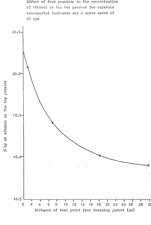
Screw speed. 2. Feed posi tion
3.
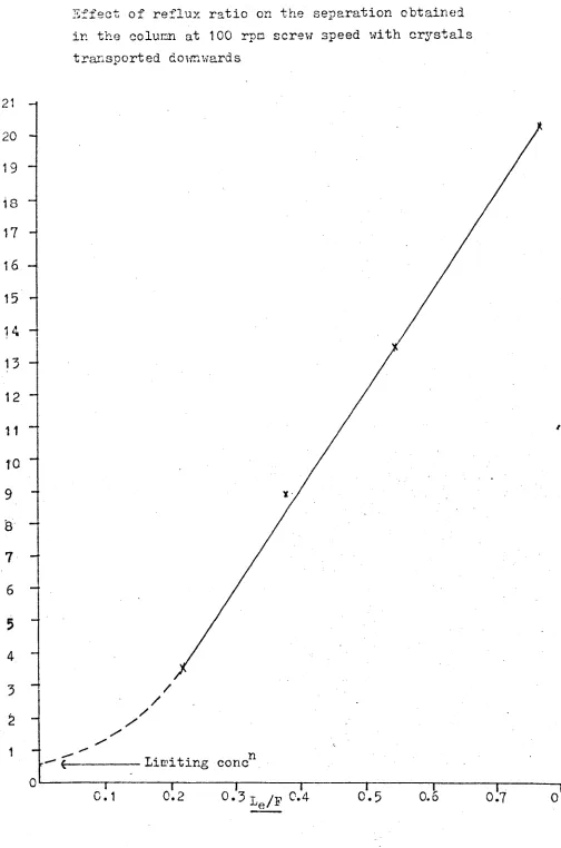
Ratio of products removal4.
.
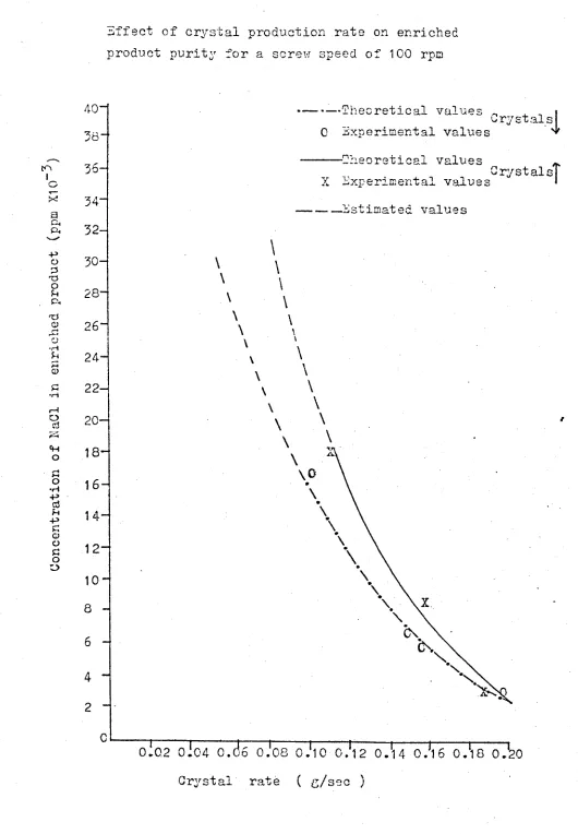
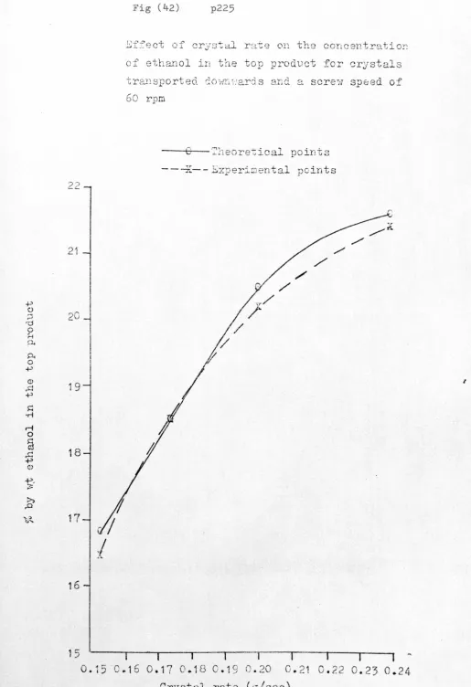
Effect of crystal rate5.
Length of purification section6.
Effect of oscillations7.
Column attitude8.
Effect of crystal shape9.
Surface finish on freezing jacket inner walls10.
Effect of diffusion and mass transfer11_ Scale-up of operations
Final conclusions 171
Su~gestions for further work 172
List of symbols 173-174
Bibliography 175-182
INTRODUCTION
The separation and purification of components in
mixtures has' been of paramount importance to man during
his evolution. During the last 10,000 years his
advancement has depended upon agricultural pursuits,
which have relied to a large extent upon the ion
exchange capacity athe soil allowing fertilizing
agents to be firmly held during leaching. This
washing, needed to remove unwanted salts, was
initially produced by rain, but as ma~s population
and hence food requirements increased, the intensive
farming needed relied more and more upon fresh water
storage and irrigation.
As an important separation process, distillation:
has been in evidence since the formation of the oceans
due to the evaporation of water and subsequent
precipit'ation as rain. Crystallisation, however,
is an even older fractionation process; the oldest
example being the solidification of themrths molten
)
later, the magma.
Ever since man has extensively sailed the oceans
he has probablY. known that sea ice contains less
salt than the surrounding water although the first
report of this is attributed to the Danish physician
Thomas Bartholinus(97) in the 17th century. However,
it was not until 1786 that the Italian Anton Maria
Lorgna(97) published results of his experiments in
/
successively froze the liquid obtained from the
melted ice five times and produced water with just a
trace of salt.
The crystalline state belongs to the solid
phase of matter; the purification which occurs upon
freezing of a solution or melt is due to the inability
of the rigid crystal lattice to tolerate the presence
of other species.
Fractional crystallisation concerns the
separation and purification of a mixture by the
dissolution and formation of crystals. For the
liquid/solid phases this process is possible by two
mechanisms. The first is the purification of a
solid by the addition of a solvent subsequently
crystallising out the pure product (eg removal of
trace impurities of potassium nitrate from sodium
nitrate by solution in water) - known as fractional
crystallisation (from a solution). The second technique,
fractional solidification, utilises che solid/liquid
phase transition without the addition of a solvent (eg
the desalination of sea water).
Fractional solidification has many analogies
with fractional distillation, ..";' 'the former
case purification being due to a liquid/solid phase
transition is similar to the liquid/vapour transition which
takes place during distL..llation. Both systems depend
upon a concentration difference between two phases at
equilibruim and separation of these phases from each
is continued since both processes can be operated
batchwise or continuously using countercurrent flow
techniques.
However, differences between the two processes
include the change in solubility when the liquid to
solid phase change occurs - solid solubility usually
being low whereas warm liquid mixtures are often
completely miscible, the effect of pressure (there
being:little change for the solid/liquid phase
whereas the liquid/vapour phase is very dependent)
and the loss of convective mixing once the solid
phase is formed causing large concentration differences
within the crystal.
Distillation is a relatively well practised
technology but suffers from several disadvantages
when compared to crystallisation
processes:-(i) the need for a large capital outlay to construct
the plant since the vapour phase is involved
and larger vol~~~s have to be contained at
equivalent pressures.
the energy required to overcome the latent
(ii)
(iii)
heat of evaporation -eg for sea water
desalination the latent head of evaporation
of water is approximatley seven times that
for fusion.
The cost of separation of close boiling components
is often prohibitively high (eg the separation of
and 1390 C, respectively) whereas the fractional
solidification process is simple (freezing points,
+13.20 C for para and
-54.8
0 C for the meta-xylene)(iv) heat sensitive compounds (eg pharmaceuticals
and flavours) cannot be purified by distillation
due ~o decomposition.
(v) the increased fire risk involved by producing
hot organic vapours, especially in the
petrole~~ industry.
(vi) for the desalination process cor-r-oaLon. and
soaling problems are readily apparent during
operation of distillation plants; at low
temperatures this problem is greatly reduced.
Crystallisation processes have been applied to both
aqueous and organic systems.
An
application receivingincreasing attention is the use of freezing techniques
to desalinate sea water since the total energy
requirement is almost half that for distillatioJ~29)
The need for a comprehensive water recovery policy
is becoming evident to most nations since even though
,
the earth is the water-rich- planet of this solar
system,
99%
of that total water is either salty oris
10cked up in the polar regions. The prob1embecomes even more critical when one considers the
race that 71% of the earth is covered by oceans and
of the remainder
60%
of the land area is arid orsemi-arid. These arid areas, generally considered
uninhabitable, could become fertile if a fresh water
Obviously marls ability to survive is limited by
the availability of potable water. Potable water is
considered to be that containing no more than 500 ppm
of dissolved salts, although, in some parts of the
world, people are able to survive on water containing
greater than 1000 ppm of salts(80).
Rain is the natural source of fresh water, 340
x 1012 US gallons per day being precipitated on the
earths surface, averaging 50 inches per year overall.
However , the spread is not uniform; some areas (eg
the North Chilean desert) receive almost zero rain
fall per year whereas in some tropical forests over
1000 inches/year are recorded.
Traditionally, water supply has been by means of
storage in reservoirs and subsequent transportation
by aqueducts, as necessary. However, the minimum
total requirement to sustain human life assuming a
diet of beef-protein, fat and vegetables is 2500 US
gallons per day per person due to the needs of
agriculture. Thus as the population increases, the
supply of fresh water by means of traditional methods
only may not be possible. If this situation should
arise then a desalination process will be required in
order to augment the traditional method. In fact ,
several large desalination plants producing a total
of 50 million gallons per day world-wide (compared to
the proposed.600 x 109 US gallons per day needed in
the USA by1980) have been built and as technology
approaching those of new reservoirs and aqueduct
systems.
Organic systems have also been separated and
purified by crystallisation. The traditional method
of producing pnn,'3 laboratory samples is to dissolve
them in a suitable warm solvent, filter the solution
and cool the filtrate : to recrystallise the product
which is then dried by filtration and evaporation at
a suitable temperature (lower than the melting or
decomposition point of the product). This separation
is based upon the differing solubility of the pure
product and the impurity i'n the solvent, either may be
the more soluble but it is preferable that all the
impurity remains ,in solution on recrystallisation.
Solvents of ultrahigh purity have unique and
unusual applications. One example is the extraction
with benzene of carbonaceous materials from meteorites
for analysis. These analyses, hampered by impurities
in the benzene, help determine the possibilities of
life forms existing outside those on earth. Both
binary and multicomponent systems have been separated
(90, 116, 119)
•
Organic mixtures with one component having a
freezing point temperature between -lOoC and +600
c
can be economically and effectively purified by
crystallisation techniques. Once the temperatures
o
of freezing points decrease far below -10 C the cost
of refrigeration increases and the separation becomes
less economically viable. .Crystallisation also allows
'.
point components (eg benzene +5.5°C and cyclohexane
+6.2oC) provided that one is considerably in excess
(eg a benzene solution containing 3% cyclohexane) and
the problem of constant boiling azeotropes experienced
in some distillations (ego ethanol and water where
further separation requires special techniques) can
be overcome by crystallisation.
The industrial applications of organic
crystallis-ation are not confined to the production of pure solid
substances. The Phillips(92, 93) system for the
purification of para-xylene from a mixture of its
isomers has now been scaled-up to a plant capable of
producing 60,000 metric tons per year of para-xylene
and the petroleum industry, where distillation is
extensively employed is considering low temperature
crystallisation as a separation technique(96).
Thus the crystallisation process is becoming an
economically viable and efficient separation method.
Its potential applications are widespread with
particular importance being stressed for its use
where heat sensitive and highly inflammable compounds
are involved. The desalination of sea water by the
vacuum freeze-vapour compression method is already
producing 250,000
us
gallons per day at Eilat inIsrael(12?>.and a.comparative analysis of desalination
processes has shown that freezing could be the most
to ° ° th UK(141)
LITERATURE SURVEY
1. Crystallisation
Batch crystallistion requires the separation of
mother liquor from the crystal and washing of the
solid to remove the adhering liquid, this is most
easily facilitated by use of centrifugation(110) •
.Briggs (28, 29, 30) working for the Coal Tar
Research Association studied the purification of
napthalene samples by centrifuging the crystals and
washing with an aqueous detergent or methanol. He
discovered that the contaminants of crystal naphthalene
were caused by intra crystalline solid solutions and
mother liquor adherence.
In 1971 Cutts(43) studied solvent crystallisation
processes involving stirring a crystal slurry in a
,solvent before centrifuging, washing the crystals
with; a solvent while in the centrifuge or a combination
of the two processes. He purified 73.5% benzene in
toluene up to 99.85% benzene which is a purity better
than for centrifuging only. However, although he
expLains the energy advantages of freezing over
heating processes the proposed commercial plant
involves two distillation columns as well as a
centrifuge.
"'
Another crystallisation technique developed from
its inception in 1952 by Pfann(106) is known as
zone-melting. This was developed to overcome the problem
of batch progressive freezing where it is necessary
to discard a portion of the solid after each
In zone melting only a thin zone of the solid is ~elted,
this zone is caused to move slowly through the solid
from one end to the other, either by moving the solid
or by moving the heater. Many subsequent zones may
easily be caused to follow the first, wLt.h each
contributing to the separation of components.
Zone-melting has proved very useful in the production
of ultra-pure materials, especially semi-conductors
(134, 14
8);
Federova and Federova(56) and Cheng andPigford(36) have both explained the mechanisms
involved.
In 1962
Ehlih
,,(53) described a technique calledzone precipitation which was similar to zone melting.
In this case a solvent is added to the mixture to
produce a gel-like liquid - the solvent itself does
not have to solidify. On heating a zone the solid
•
melts and as the zone moves the liquid behind
solidi-fies, rejecting the most soluble components. Solids
of greatest solubility are concentrated in the
direction of movement, the fractionation being
improved by use of solvents which reduce the liquid
viscosity in the molten zone. He used the technique
for separating petroleum waxes.
However, due to the difficulty of producing
continuous zone-melting equipment the technique has
2. Column Crystallisation
As recently as 1973 Knox(82} stated that
multi-stage crystallisation could not be carried out;
simultaneous production of crystals, melting of those
crystals and the washing of the crystals was not yet
possible. The method of zone-melting in whichfue
processes occur sequentially was described but column
crystallisation was never mentioned.
However, as early as 1951 Arnold(12} had
performed several experimental runs on a column
crystalliser. His crystalliser had no transportation
mechanism for' the crystals but he employed a pulsed
countercurrent flow of melt liquid and small crystals.
The significant suggestions made by Arnold were the
use of a scrap(er if the cr~stals adhered to the
cooling walls and some form of transportation (by
buckets) if the crystals did not move freely along
the column.
The next development was due to the Phillips
Petroleum Co. USA. Hackmuth(68) developed the
concept of Arnold; he combined pulsed flow and the .
sugges cion of a scr-ap;ed freezing section plus crystal
transportation. Crystals are introduced to the
column, compressed by a hydraulic piston which is
porous to the mother liquor. The crystals are forced
into a grid and onto a melting section where the pure
product is withdrawn. This form of column crystalliser
design was improved by MCKay(90) who constructed a
reciprocating porous piston to push the crystals down
the column. The mother liquor was removed from the
piston by means of a vacuum line and a heater a-t the
base of the column melted the crystals. He raised a
77% p-xylene feed up to
98%
but could only manage lowflow rates of feed and product.
Schilill<necht(117, 118) described a similar
design of column crystalliser, but he used a helix
rotating at 80 - 150 rpm to transport the crystals and
scrape the freezing section. His ini ti al des Lgne s
were very small-scale~ 13 - 15 em long with a volume
of approximately l5ml and operated batchwise e- " The
inherent difference between this design and the
crystallisers using a reciprocating piston was that
the crystals were actually formed in the column and
not in an external unit. Hence the problem of moving
slurries from once piece of apparatus to the next was
removed; crystallisation, melting, possible
recrystal-lisation for solid solutions, and washing were carried
out in one piece of equipment. The freezing section
of the column could be at the top or base of the
column, a melting section to melt the crystals being
required at the opposite extremity of the column.
The transportation helix was wound round a stationary
central cylinder concentric to the containing walls
of the crystalliser.
In 1962 Beattie and Gold(20) produced a type of
column crystalliser operating in the horizontal plane.
bath. Crystals form on the jacket and are carried
to a heating element by rotating the jacket. By use
of a helical thread along the colwnn the melted liquid
then progresses to the next crystallisation section where
the process is repeated. Using several crystallisation
sections suitable separations can be attained.
The design of crystallisation equipment was
still: largely an art by 1963 when Anikin(3) attempted
to model the concentration profile produced in a column
crystalliser. He considered a stage-wise operation
as in distillation columns, but his model was only
concerned with recrystallisation, the effects of
washing being neglected.
Meanwhile, continued improvements to the
established column crysta1lisers led to several
patented designs. Phillips Petroleum of the USA
took out a patent on ~1cKaY'sI(91) reciproca ting pis ton
crystalliser and McCarthy(89) further adapted this
design by having a stationary porous section in
approximately the m£d-point of the column and
producing a high pressure, low frequency pulse to
move the crystals. The Sun Oil Co. of Philadelphia
patented a design of BotWer(24). This crystalliser
was cooled by a concentric tube through the centre of
the column and the crystals formed moved by applying
a cykic pressure pulse. The feed was centrally
posi-tioned and the products were distilled.
In 1967, McKay(92, 93) described the scale-up
of operations of the p-xylene purification plant.
purified to 99
+
\'1t%at 530 Kg/hr and the capacityof operating and announced plants at. that time \'las
130,000 tons/yr. During the same year Schilill<necht
(119) demonstrated the suitability of conti~uous
column crystallisers in the production of ultra-pure
ao Lven t.e , He produced 30 ml of benzene per hour in
which no impurities could be detected by gas liquid
chromatography.
The possibility of wide applications for column
crystallisers was demonstrated by Betts etal(22).
Using a continuous column crystalliser of Schilill<necht
design he purified or concentrated various organic or
aqueous solutions. However, his flow rates were
usually low; any attempts at; feed rates above lKg/hr
produced poor separat;ions. Considering the experimental
work undertaken the analysis of column operation should
have been simple; however, this was not attemp_ted.
Continued work on the analysis of the column
crystalliser led to descriptions by Devyatykh(49)
Arkenbout(8, 9) and Powers(2). The former developed
a model of col~nn crystallisation based upon
diffusion in the solid phase being the rate
determining stage in mass exchange between the
liquid and the crystals. Arkenbout recognised that
the column equation for exchange processes could be
modified and introduced an expression for the inter
facial mass transfer by extractive washing and
recrystallisation whereas Powers having demonstrated
the applicability of column crystallisers, developed
adhering and free liquids and diffusion along the
column. The solution of Powers was different for
eutectic systems and systems forming solid solutions
whereas Arkenbout produced a generally applicable
equation.
Fo.Lkowdrrg much research into the design of
column crystallisers(59, 60), the Coal Tar Research
Corporation(4l) patented a reflux crystalliser.
The design incorporated a pulsed feed of crystal
slurry to the centre of the column. Part of both
the low and high melting point products are recycled
to the column and crystal transport is facilitated by
means of a polished helical conveyor. Armstrong(10)
however, described the design of a scraped shell
crystal1iser and its possible applications to the
dewaxing of petroleum
oils,
preparation of fattyacids and the separation of isomers.
In 1969 and 1970 mathematical modelling of
column crystal1isers was undertaken by several
workers. Player(107) analysed the operation of
both Phillips and Schildknecht type columns and
explained the differences between the two designs.
For the end-fed porous piston column refreezing is
a dominant factor. If too pure a feed material is
employed, little refreezing occurs and the crystal
bed is then too porous to prevent channelling of the
mother liquor into the melting zone. However, for
centre fed columns of Schi1knecht design, refreezing
is minimal since the feed is only 1 - ~;. impure
obtained in Phillips type col~~ns is not demonstrated
under centre bed column operation.
Bolsaitis(2S)
modelled a Schildknecht typecolumn; he split the column into a stripping section
where the crystals were formed and an enriching section
where the washing occurred. The performance of the
stripping section was described by a stripping
efficiency, defined as the fraction or percentage of
crystallisable material which is removed from the
solution entering that section. Once the crystals
form they are acted upon by gravitational, bouyant
and viscous drag forces which lead to a minimum size
of crystal above which transport.ation is allowed, the
smaller-crystals leaving with the stripped stream.
Unfortunately, the enriching section equations only apply
to cases where the volumesof desired product and
impurity are approximately equal.
Powers continued the work on the analysis of
column crystallisers. With Albertins(l) he
developed a moda for batch operation considering
three distinct cases:
(a) Crystal was pure
(b) crystal impurity was constant along the
length of the column but diffusion was
negligible in determining the concentration
profile.
(c) crystal impurity was constant along the length
of the column but diffusion was the dominant
Since the crystals were demonstrated to be impure,
cases (b) and (c) were considered. If di.ffusion was
dom.i.nanb , as the crys tal production rate was increased
then the p1rity of the enriched product should increase
whereas for mass transfer dominant ·the converse
is
true.The experimental results(l) proved diffusion to be
the most important factor in determining the
concentration profile
in
the column.In an attempt to provide a better assessment of
the column performance Gates and Powers(6l) repeated
the model of batch operation. The development of
equations for systems with solid solubility and for
eutectic systems allows a fuller analysis. By use
of equations including diffusion coefficients and
mass transfer coefficients, assuming that the crystal
impurity was constant along the length of the colUmn
they obtimed better results for the coefficients.
Continuous column crystallisation was modelled
by Henry and Powers (72, 73) by studying the reduction
of cyclohexane
in
benzene. The experimental workemployed a column of 300 ml volume, maximum flow
rate of 300g/hr for feed of 28000 ppm cyclohexane.
For a ratio of enriched product to feed rate of 0.16
they obtained a pu~e product of 40 ppm impurity.
The model of the column performance, essentially
based upon equations for extraction columns,
is
separated, as was Bolsaitis' model(25), into a
stripping section profile and an enriching section
column concentration profile are the crystal rate,
diffusion of impurity along the column and mass transfer
between the free and adhering liquids. However, the
model breaks down as -the enriched product r-ate
approaches the value of the crystal rate due to the
flat composition profile obtained.
During 1970 a design of column crystalliser by
Richmond and Exley was patented by Newton Chambers(lll).
The apparatus was essentially of Schildknecht design
using a central feed point and a helical conveyor
capable of driving the crystals downwards. The
patent specification included a design where the
crystal conveyor was a screw since the helix would
often "siez@ ..up'; in the column.
In the same year Schi1ill<necht etal(l~) described
the operation of a column crystalliser with a pulsating
spiral conveyor. The volume of the column used was
250 ml, the pulsations were employed
to
decreasethe tendency of the ~olumn
to
block with crystals.The spiral was rotated at 70 - 80r.:pm.,driving the
crystals downwards and oscillated 180 - 330 times
per minute through a distance of
3 - 6
mm. For afeed rate up to l30g/hr the separations were acceptable
but on attempting to :increase the rates the purification
was adversely affected.
A novel type of column crystalliser referred to
as the Brodie-type design was announced in
(4)
and(31) •
The equipment was essentially an L shapedsection with the horizontal arm at .the top. This
to a refining section on the same arm. Crystals formed
in
the cold area of the recovery section are conveyedcounter~urrently to the feed towards the refining
section. On entering the latter section the crystals
are waab ed by a liquid reflux stream before entering
the vertical arm of the apparatus - the purifying
section. At the base of the purifying section the
crystals are melted to form the desired product and
reflux liquid. The product is removed at the base
of the purifying section and the reflux liquid forced
back along the column.
t-1atz(88)inve etigated the operation of a worm
,
crystalliser in 1972. This type of crystalliser
employs a helix driven in the opposite direction to
a central cored shaft through which a heat transfer
medium can pass. The outer jacket contains three
heated sections, one above the centrally placed feed
point and two below. The apparatus was suitable for
COarse separation but not for ultra-purification.
Scale-up of operations using Schildknecht type
column crystallisers was undertaken by Hobson and
McGrath(74). Using data obtained from a 50mm internal
diameter, 90cm in length column they built a column
of 100mm diameter and 150 cm in length with an
employable volume of
3.8
litres. However, thislatter column was essentially filled with the
Archimedean screw conveyor and the cooling apparatus
available not sufficient to allow a complete analysis
The recognition that column operation would
probably be improved by cutting the volume occupied
by the conveyor mechanism was employed by Moyers(95).
The freezing section contained a wall scraper which was
rotated and osciDated to keep the walls clear of
crystals. The drive to the scraper causes a piston
to be actuated which
in
turn drives the crystals intothe purification section which
is
free of internalmembers. The~ystalliser used a central feed point
and the crystals were transported downwards.
However, the apparatus described only allowed low flow
r-abea of feed (up to 330ml/hr) and separations were
not very efficient, any attempt to remove a significant
fraction (0.4 - 0.5) of the feed as pure product
increased the impurity content
\in
excess ofl lOOOppmfrom a feed of 40,000 ppm acetamide
in
water.Development of column crystallisation apparatus
has also led.:to designs where the desired product
is
crystalline(135). Erbe(S5) and Weech(14S) describe·
equipment in 2 US Patents. The former apparatus
consists of a horizontal jacket oont ad.nd.ng'a spiral
oscillating longitudually. Kneading teeth. are
a ttached to the jacket b ebwe en the spirals wh Lch
allow a conveying action. The melt is added at
one end of the equipment and the crystalline product
leaves from the other extremity. The design of
\veech(145) is much more complex, being used to
purify aluminium nitrate by alternate melting and
top of the column into a chilling section. The
crystals produced move to a melting and recrystallising
section. Finally the crystals are reformed in a
second chilling section before removal of product.
Wash liquid, in which the crystals are insoluble,
enters below the lower chilling section and removed at ...<
3. Desalination
Desalted water has been ava:ilal.blefrom the oceans
ever since their formation. Evaporation and
eventual precipitation as rain together with the
freezing processes occurring at the North and South
pole has provided sources of drinkable water.
Utilisation of the evaporation/precipitation
process for. purifying
sait.
waber- has been utilisedby man
in
the form of dist:illa:tion·-,·.apparatus.Disti .llation processes are basically those
in
whichsaline water
is
evaporated, pure water being obtainedby condensation.
Several designs of distillation apparatus for
desa.lination have been suggested.
Multi stage flash distillation has been
extensively described by Frankel(S7)and Silver(129).
In this process heated brine enters a chamber maintained
at a reduced pressure. Some of the wat.er-immediately
evaporates (flashes) and ·then condenses on tubes
cooled by the feed of sea water flowing to the steam
heated input section. A series of such chambers
(stages) at progessively reduced pressures forms the
plant. The feed sea water increases in temperature
as it is passed through the condenser tubes in the
opposite direction to the flashing flow. The
condensed:~ ..steam is collected on trays b eLow t.he
condensers;product water emerging from the last stage.
The desalination of sea water by multiple effect
.
(131 141)
evaporat10n ' has been shown to have certain
Standiford(13l). The process is basically one in
which steam is used
GO
evaporate some of the seawater in the first effect, the vapour condensing
in the second, lower temperature effect, evaporating
more water and so on. There may be as many as 20
effects in a commercial plant. A large plant has
the following economical advantages over a multi-stage
flash distillation
rig:-(1) heat transfer coefficients are generally higher;
(2) more of the available temperature difference
can be used for heat transfer and (3) less pumping
energy is required for a mUltiple effect evaporater.
Silver(129) described a process 'known as vapour
compression evaporation where steam generated from
boiling brine is mechanically compressed to increase
the vapour pressure and condens acdon temperature.
The steam is fed to an evaporator tube bundle where
it condenses forming product water and in doing so
evaporates m~re brine. This equipment has a low
energy consumption but the energy form is expensive
(electrical) so the plants are often small.
All the above distillation processes suffer from
several disadvantages:
(a) the high energy requirements to overcome the
latent heat of evaporation.
(b) corrosion problems are high due to the
elevated temperature employed.
(c) scale is easily formed at the temperatures
required.
and ambient is large. Hence insulation becomes a
problem.
Some of these problems can be overcome by using
the sun as a source of energy - solar distillation
(141)
The energy source for this equipment is
free, if not always available and ~the scaling
problem is removed. The principle of operation
requires-the placing of sea water in flat tanks with
a roof of glass or tough transparent plastic. The
solar heat vapourises the water which vapour condens~s
on the inside of the roof, draining off as fresh water.
Its major disadvantage is the requirement of a large
land area/unit of product.
Cheap readily available sources of energy are
also provided by nuclear power stations leading to
the proposal of nuclear distillation plants(4
8)
andBarnea and Weyelin (17) suggested t.he use of geothermal
fluids or geopressure reservoirs as a source of energy
for multi-stage flash distillation. The main problem,
however, was found to be the formation and removal
of deposits contained in the fluids which affect heat
transfer.
In order to alleviate the energy problem inherent
in distillation equipment other separation techniques
have been attempted to desalinate sea water. The
theoretically most attractive of these systems is
reverse osmosis(78,
SS,
129). In this process asemi-permeable membrane is employed. By the application
of a pressure in excess of the osmotic pressure of
brine to a fresh water compartment. Unfortunately,
the pressure required is proportional
to
the salinityof t.he feed. For 5000 ppm dissolved salts the
applied pressure employed is 40 atmospheres and for
35000 ppm, 100 atmospher es-..Hence the system is
usually only used for brackish waters.
Similarly, elec-trodialysis is used to desalinate
brackish water due to the increasing costs as ~he
salinity of the feed rises. Electrodialysis
(127, 129) employs the transfer of.ions through a
membrane under the influence of an electrical
potential difference. The positively charged metal
ions and the anions move towards the electrodes
through membranes permeable bo either cations or
anions - hence the gap between the membranes become
depleted in ions. In theory the process is optimised
for a high current density and a small membrane.
However, a high current density causes concentration
polarisation causing a wastage of power along with
appreciable scaling.
Salt water has also been desalinated by use of
ion eJehange resins (
7)
and sol vent extraction.Davison(44) described a solvent extraction plant
which is dependent upon the solubility characteristics
of certain secondary and tertiary amines with water
and salt water. The solubility of water in the
solvent which!selectively dissolves water from salt
water- solutions ::is very sensitive to temperature:.
decreases with increasing temperature and salinity
and the selectivity decreases with increasing water
content. Thus
it
is necessary to determine anoptimum water content and the feed material used
contains only 4000 to 9000 ppm salt.
Ion exchange processes(115, 141) usually employ
a feed of only 10ffito 3000 ppm salinity. Scambarfl15)
describes an Australian process using resins which can
be regenerated with hot water. The product water
has 50 - 100 ppm dissolved salts and is used mainly
as boiler water.
A novel method of d~salination has been demonstrated
by Avampto(6). This process is baQed upon the
bending of the path of an ion by use of a magnet.
Salt water is channelled through a pipe past an
ul tra-violet or X-ray source which further Lon Laes :
the ions of dissolved salts. The water then passes
a magnet which deflects the ions away from the centre
of the pipe. The relatively purer water at the
centre is removed via an internal pipe set
concent-rically within the original one and the less pure
water goes to waste. Although claims of removing
92% of the ions have been made values of 15% removal
are more usual for a 3.5% sodium chloride solution.
Gillam and MCCOy(129) have postulated that by
1980 the energy cost of producing 1000 US gallons
of potable water from' aea, water by distillation
processes will be 180 Kw-hr compared to 35 Kw-hr
for freezing processes (and 30 Kw-hr for reverse
two processes using brackish water as feed).
By
1975
Strobel(133) predicts that desalinationwater costs will be CB low as 15 cents/IOOO US gallons
and Ennis(54) suggested that even in 1970 the costs
of producing potable water by conventional storage
methods (dams, reservoirs) and by desalination
overlapped if a large plant was considered whereas
by 1980 desal~ing will be at least as economically
viable as conventional methods for plants producing
50 x
10
6
us
gallons/day of product water.With freezing processes appearing to be so
economically acceptable much research into the type
and design of various plants has been undertaken(64).
The early experiments in purifying sea water by
freezing are described by Nebbia(97). The
observation that water obtained by melting ice formed
in sea water was fresh had been reported almost
simultaneously by Bartholinus and Boyle in the 17th
century but it was not until 1786 that Lorgna
developed a working method for water desalination by
freezing. By repeated freezing of the melt liquid
obtained from the previous crystallisation he reduced
water of 36,200 ppm to 800 ppm in three stages. On
continuation to a 4th and
5th
stage the melt waterwas essentially pure.
By 1908 Buchanan(32), after his Antartic cruise
of
1874
in the Challenger and Petterssen on the Vegain l87~, had analysed sea ice and found it to be
pieces of glaciers and occluded liquid brine.
Buchanan had thus recorded that the freezing of a
dilute solution can lead to purification of the
solvent by rejection of the solutes into the melt.
The earliest extensive use of freezing as a
method of desalting water was reported by Whitney
in 1944(147). In this process ice was formed from
impure water by causing a jet of water, at low
temperature, to be forcibly projected against a
surface maintained at a temperature low enough to
allow the.progressive accumulation of ice to occur
on that surface. The velocity of the water is so
great that the impurities rejected by the ice
formation are washed away as fast as they appear.
By 1967 several experimental freeze-desalination
plants had been designed and constructed.
were described by Barduhn(15).
These
Vacuum flash freezing process
This is also called vacuum freez~:':"'vapour
compression desalination. The process is further
described by Bridge eta~2;~ck(103), Pachter(102),
Barduhn(16), and synder(129} whereas Schwatz(12l)
analysed the operation of the counterwashes used
to wash the ice crystals.
Operation of the plant is based upon using
water as a ref rigerant. Sea water is introduced
to a vacuum chamber maintained at a pressure
equivalent to the vapour pr-essur-e of sea water at
or below the freezing point. . Some water flashes
due to the requirements of latent beat for
evaporation. Crystals form in the remaining water,
the slurry is separated and the ice moved to a
washing/melting unit where some of the melt water is
used to wash the crystals. Schwartz(l2l) developed
a model of the counterwasher in which brine is
displaced by fresh water from the interstices of the
ice plug. He discovered that output increased with
an increase in the ice crystal size, the plug length
above the screens in the washer, the concentration
of ice in the slurry and the external mechanical
restraining forces on the ice plug whereas the
production increases with a decrease in the ice plug
length below the screens.
Butane f·
(5, 15, 16, 47, 83)
reez1ng process
This system has been extensively studied by the
United Kingdon Atomic Energy Authority (m<AEA). The
secondary rebigerant freezing process uses a liquid
hydrocarbon refrigerant (eg butane) which is
immiscible with water. By direct contact with salt
water the butane is vaporised due to the heat transfer.
The salt water freezes producing an ice/brine slurry;
the crystals are separated and washed to remove the
brine. The ice is then melted to produce product
water by contact with compressed butane vapour which
has passed from the crystalliser to the melter for
reuse. Crystal gr-owbh needs strict monitoring to
allow for effective washing but still a but~~e taste
for human use and it must be removed thus increasing
the cost of the water. In 1970, the British
Government revealed plans to build a butane freeze
water treatment plant near Ipswich. This crystalliser
wa~ to be used to produce one million gallons of
fresh water per day compared to the largest similar
plant operating at present producing ten thousand
gallons/day at Stockport. Unfortunately, by 1972
the decision to postpone the construction of the
Ipswich Plant was taken by the Government.
Similarly in the USA the Office of Saline Water
I'
(OS\'l) have ceased to fund pilot plant work on
secondary refrigerant freezing, stating that
progress was too slow due to a high degree of coupling
between components causing data evaluation and
scale-up to be difficult.
Attempts to improve the secondary refrigerant
process have been made. Fraser(5
8)
used a non-toxic,non fLammab Le f'Luor.r-oc ar-bon refrigerant and estimated
a cost of
69
cents/lOOO gallons for a 1 million gallon/day plant. The use of 80/20 mixtures of iso-and
normal butane has also been tried(lS, 16), Carrier(lS}
have employed octa fluoro cyclobutane\and Johnson
(76)
in Aveo's Crystalex process used Freon 114I
which are both highly insoluble in water, non-toxic
and non flammable.
The major drawback of all primary and secondary
refrigerant crystallisation plants is the requirement
of dividing the plant into three distinct parts,
of slurries and the extra insulation expense. The
primary refrigerant system also suffers from a need to
work under vacuum hence plant costs will be high since
loss of the vacuum would be disadvantageous and in
fact after several years running the plant at Eilat,
Israel was shut down(6S) in 1973.
(15 16 129)
Hydrates ' ,
In order to alleviate the problems of low
temperature running in crystallisers, several workers
have employed hydrate formation. For this process
the water solidifies and precipitates at a higher
temperature and pressure .than does pure ice. The ice
formed contains no salt but has
5 -
15% hydratingagent incorporated in it. The hydrating agent
(e.g propane) is removed on melting since it is chosen
to be insoluble in water. Obhe r-wd.se , the system is
similar to normal freezing units, i.e. it requires
a reaction vessel (where hydrate forms), a separator,
a melter and a washer. Unfortunately, the reaction
of the hydrating agent with water to produce the
solid hydrate occurs at an even slower rate than the
freezing of ice and the separation of solid crystals
and washing are more difficult than with ice.
In a novel paper, Wankat(l43) described
desalination by natural freezing. This process is
applicable in relatively warm climates with ambient
temperatures above freezing and the melted ice from
a single freezing, without washing, was 3-6 times
shallow, well insulated container with a shallow
layer of water. The rig should be level and have a
completely clear exposure to the night sky. During
the night the energy balance over the rig shows that
heat is lost from the water by r-addat.Lon to the nigh t
sky and heat is gained by conduction from the ground and
convection from the air. In addition if the humidity
is low then heat is lost by evaporation or if the
h~~idity is high then heat is gained by condensation.
Under these conditions radiation ,viII be the dominant
factor and the water layer cools, possib~ freezing.
The use of continuous column crystallisation in
desalination was described by Hobson and McGrath(74)
This process has the advantage over other freezing
processes in that the crystallisation, washing and
melting process occur in one piece of apparatus.
The cystal size produced is dependent upon the
rotational speed of the conveyor according to
. ,( 25) 11 h I'
Bolsa1t1s as we as t e coo 1ng rate. Thus control
of washing by producing suitably sized crystals is
more easily facilitated than in other types of
crystalliseI'. Due to the problems of cooling in
the larger crystalliseI' described (lOOmm diameter
1.5
metre long) they proposed using a butane freezerto produce the crystals. In fact this was
unneces-sary, redesigning the conveyor mechanism to markedly
increase the annular volume of the crystalliser and
reduction of the mass of the materials used in the
large amounts of concentrated brine. Some workers
have proposed by-product recovery systems. Goto ..
(67) etal considered potassium recovery and sodium,
potassium and magnesium have been extracted by the
Chemical and Technical Services of Kingston-upon-ThameJ}S)
In an attempt to reduce the volume of waste
brine from crystallisation processes Avco extended
their Crystalex process to a Eutectic Freezing
process(132) in which ice together with sodium chloride
dihydrate are simultaneously formed. The operation of
the apparatus requires crystallisation of the ice and
salt hydrate, separation of the ice and hydrate crystals
from a eutectic slurry, countercurrent washing of the
eutectic ice and then drying of the hydrate crystals.
The experiments so far have used feed of only 5000 ppm
sodium chloride and the washing of the ice has been
difficult due to the small crystals produced.
The crystallisation processes occuring upon
freezing salt water solutions have been extensively
studied(42, 45, 69, 70, 71). In 1967 Marriot(69)
examined the gro\rth of ice crystals in a stirred tank.
The crystals were grO\ffiby direct contact with
evaporating butane. For water subcooled 0.01 to
O.OSoC,
the particles grew abouti
to!
as fast aspredicted from heat transfer correlations. The
growth rates in 2% salt solutions were about sevenfold
lower than those for pure water because ,.: the
concen-tration difference for salt diffusion lowered the
shown to be much greater for disc shaped particles
than for spheres.
Terwilliger(137) studied the salt redistribution
process during the freezing of sodium chloride
solutions. The process was found to depend upon:
(a) the liquid phase interface concentration
which is controlled by the supercooling
(b) the thermal driving force imposed to
initiate and maintain freezing.
His findings contradict other authors who believe
that rejection is caused by a distribution coefficient
dependent upon the freezing rate. This investigation
showed that the distribution coefficient was only
indirectly a function of the freezing rate.
The performance of a continuous well stirred
ice crystalliser was described by Marjolis etal(86)
in 1971. Photographs demonstrated that the ice
particles were disc shaped and the permeability of
the ice beds were found to depend upon the size and
shape of the crystals and the method of forming the
beds.
In two papers by Janzow and Chao (75) the
crystallisation phenomena when ice is crystallised
from brine were reported. The first paper provided
a study of sal-I;entrainment in ice crystallised from
brine. They concluded that brine adhering to the
thin plates of ice and retained in the interstices
by capillary forces is responsible for the high salt
studied crystallisation of brine solutions within a
narrow range ot' subcooled brine temperatures. Large,
plate-like free ice crystals up to several inches in
length were formed in the bulk of a slowly traversing
brine simultaneously with the growth of dendritic ice
on the cold surface. Because the crystals are lQrge
the possibility of application to freeze desalting is
noted.
The analysis of crystallisers has been much
neglected but some workers have described models.
In 1964 Godrey and Benham(66) provided an analogue
simulation of'-a continuous counter current crys talliser
using cascade from one unit to the next in order to
decrease the cost of scale-up of operations.
Orcutt(99, 100) modelled both the operation of
a well mixed crystallisation vessel and the ,nucle:ation
and growth of ice crystals in secondary refrigerant
freezing. The first paper(99) allows the vessel
size required for crystallisation, the mean particle
size, growth and nucleation rates to be calculated.
. (100)
The latter report develops a mathematical model
of the freezing/crystallisation step for secondary
)
refrigerant freezing processes. He considered the
influence of the refrigerant phase on the nucleation
rate. The crystal size distribution was estimated
assuming the crystal growth occurs by heat-transfer
....
limited growth or by growt.h accompanied by agglomeration. ~
of which the latter was considered more realistic •
...
Working with Carey, Orcutt(lOI) studied the
In order to simplify scale-up of crystallisation
processes data obtained from transient dye tracer
studies of a mixed freezer/crystalliser were
analysed by use of an anolgue model. The deadwater
region parameter was found to depend upon the specific
power input with a parameter representing the
exchange of material between the deadwater region
and the remainder of the vessel contents being:affected
by the position of the agitator.
. . (114)
During 1973 Sarcona etal derived a
mathematical model describing the steady state
operation of a continuous cooling-type crystalliser.
The analysis was tested with various sets of
hypothetical input data so as to determine crystalliser
and heat exchanger design parameters and the study
is purported to provide a .'means of solving the
engineering problems associated with the process.
Continuous column crystallisation has been
analysed by Powers etal(72, 73) by considering the
effects of crystal rate, '~ake off of products,
diffusion of impurity along the col~~n and mass
transfer of impurity between the adhering and free
liquid. The operation of the column can be
effectively simulated by use of Powers' equations
providing the take off of pure product does not
4. Ethanol Concentration
Since the earliest times in mariydifferent places
men have developed, quite independently of each other,
the fermentation of sugar containing liquids to produce
ethanol. However, the production of aqueous
ethanol solutions of high alcohol content only became
possible when distillation was invented during the
12th century. By the end of the Middle ages spirits I
were being produced and absolute ethanol was first
obtained by distillation via potash and lime.
In Germany aLcoxho L is produced almost exclusively
by fermentation(112) although the production from
ethylene bOy hydration(l4) is now more widely employed.
Most table wines contain 9 - 12% by vol of
ethanol although
18%
by vol is possible(14J. Toobtain a spirit quality beverage from fermented
liquour requires raising. the aLeo .hoL content to
32 - 33% by wt .'Disti.llation processes ~38, 63,
149) have been used most extensively to obtain this
concentration and since the boiling action
undoubtedly produces the loss of flavours, Girard
(63) worked under vacuum with a temperature of 300C.
(139)
In 1909 Traube proposed a solvent
extraction process to -recover a solution rich in
ethanol. A concentrated solution of potassium
carbonate or a~~onum sUlphate was added to the
alcohol solution. Two phases separate, the lower
being rich in the salt and poor in ethanol whereas
the upper is poor in salt and rich in ethanol and
The Institute National de~ Recherche Agronomique
at Dij:m(50) have concea ntrated wine by the fractional
crystallisation of water. In an essentially batch
process the ice/wine slurry is compressed in a
perforated cylinder and packed, the ice being expelled
by suction. The major disadvantages of the process
are its batch-wise operation and the loss of
3%
alcohol with the ice.
McKay(93) considered the possibility of
concentrating beers using the Phillips type crystalliser
in order to make storage and transportation possible.
In the USA where beers sold are usually of the keg
variety and sold at low temperature the consumer may
allow the concentration and eventual dilution of beer
whereas in this country much of the beer sold is still
of draught quality and is still 'live' in the barrel
(112) (fermentation to condition the beer is still
occurring) and concentration may well kill the
yeast present. However, the use of column
cryscallis-ation to concentrate wines etc. to spirit quality was
5. Deuterium Oxide
In 1927, Aston(13) measured the atomic wt of
hydrogen by use of a mass spectrograph and found the
value to be in good agreement with that obtained by
chemical methods. Two years later when it was
shown that naturally occurring oxygen consisted of a
mixture of 3 isotopes, it was discovered that there
was a discrepancy of the order of
Z
parts in 10,000between the two determinations of hydrogen atomic
mass. This deviation could not be accounted for
within the experimental errors and it was suggested
that the difference may be due to the presence of 1
part in 5000 of a heavy hydrogen istope of mass 2 in
the ordinary hydrogen.
The production of heavy water presents a
difficult set of problems(lZZ, 146). In natural
water there is only about 0.015% of deuterium oxide
and the method of concentration mu~t depend upon the
physical differences between hydrogen and deuterium
containing materials such as Hz,
HD,
DZ•
Themethods will involve cascade operations with a large
number of stages since the separation factors are
likely to be low.
Distillation processes for producing heavy
water concentrates was used by Pegram in 193~ and was
patented by him in 1940(10
4).
He also used hist
tt
t .. 018 dapparatus to concen ra e wa er con a1n1ng an
the only example of concentration given is that
after 50 days operation, ZOcc of water containing
operation.
Due to the high costs and poor returns from
distillation processes in concentrating heavy water,
Gehrke(62) used a partial evaporation or condensation
technique. In this process 10cc/min of water and
1L air were passed through a fritted glass filter at
200C to produce a moist gas stream containingl.l%
This stream was passed over granular basalt
o
at 95 C for 100 minutes, then an inert gas was
passed through the apparatus at 110oC, removing
water containing 25%: D20 from the basalt.
Egi(S2) and Smith(125) bo·th concentrated
deuterium oxide by use of zone melting. Egi used
a horizontal ring type vessel with a U section
equipped with movable heaters. The heaters were
moved at 2mm/min and the solid was formed by using
o
a cooling temperature of -10
c.
The feed materialwas 56.4% D20/HzO and after 26 hours the product
was 98.4% D20. Smith used an approximately
equimolarfeed but found the separation to be much
,lower than predicted by the theoretical separation
factor of 1.0211(108).
The electrolytic separation process has been
widely used since it gives a good separation(87).
By 1946 Tro.nstad(l4<)was using a series of stages and
raised the concentration of natural water up to 0.07%
In his apparatus the product from each stage
the electrolysis. A similar process was used by
Coles(39) and Bushell(33) where after electrolysis
the deuterium was recovered byliqusfying the
deuterium/hydrogen mixture and fractionally
distilling. The enriched deuterium was then
burned in air to producedeu,terium oxide.
In a report in
1941,
Johnston(77) describedthe operation in
1934
of the Ohio State UniversityI
Heavy Wate~ Plant which operated in 3 main stages.
He obtained 800 grams of heavy wa~er from a feed of
1800 gallons of water in 16 weeks.
The enrichment of heavy hydrogen by isotope
exchange has been studied by several workers(18,
23, 34, 109, 113, 128, 136, 142)
• An example of
the process is given by the hydrogen/ammonia system.
When two different hydrogen containing species such
as hydrogen and ammonia are brought into equilibrium,
the concentration of deuterium relative to hydrogen
will be different. The ratio of the concentration
of deuterium in the two species is known as the
separation factor and depends upon the temperature.
eg at -40oC Separation factor 6 )
) for H2/Nrt
3
100oC" It 2.3) system
By use of a potassium amide catalyst (0.1 to 1%
by ,,,t),working at high pressures (255 Atmospheres)
~nd with a temperature of -40°C the hydrogen (+nitrogen)
stream is countercurrently washed with ammonia. In
this apparatus 70% of the deuterium in the feed gas
Barr(19) reviewed the most economically viable exchange
reactions. These are:
(a) Hydrogen/water
(b) hydrogen/water using hydrazine as catalyst
(c) phosphine/water exchange where more hydrogen
is available
(d) hydrogen iOdide/water wh er-e equilibrium is
quick1y reached.
Both Mercea(94) and Denton(46) have patented
heavy water plants where the products of exchange
reactions are distilled to further purify the
deuterium oxide.
Other techniques of heavy. water concentration
have been proposed. Chapey(37) electrolysed
natural water to produce hydrogen containing 0.15%
HD. This was rectified at low temperature to
separate HD from HZ giving a product of 60% HD.
This was oxidised and rectif!~d to give99.S%·
deuterium oxide. Brancker(Z6) suggested using,
solar energy for distilling heavy water in order
to reduce the high cost whereas Cross(40) purported
that light and heavy water should be separable by
using centrifugal forces.
The difference in freezing points between heav~
water(SI) (3.SoC) and light water (O.OoC) suggests
that separation by multi-stage crystallisation,
especially if concentrates are used as feed
material, should be possible. Thus the application
of continuous column crystallisation to deuterium
THEORY
1. Mechanism of Crystallisation(96, 98, 150)
The production of crystals from a solution is
governed by three basic steps:
(a) the attainment of supersaturation or
supercooling
(b) the formation of crystal nuclei
(c) the growth of the crystals
(a) Supersaturation
A saturated solution is one which is in
equil ilu:-Ul.mwith the solid phase. If more
solid is dissolved in the solution a
supersaturated condition is obtained.
This state of supersaturation is an
essential feature of all crystallisation
operations and can be achieved by cooling,
evaporation, addition of precipitant (or
diluent) or by chemical reaction.
Ostwald (1897) was the first to
introduce the terms 'labile' and 'metastable'
supersaturation. In the former case
spontaneous deposition of crystals will
occur from a superaturated solution, whereas
in the latter spontaneous crystallisation
D
C
/
/
/
//
/ b
/
t
a~/t
as.-1fe
./
.B
Labile
Stable Concn
Temperature
In Fig (10) line AB represents the
normal solid solubility curve for the solid
concerned. The line CD, referred to as the
supersolubility curve, gives those temperatures
and concentrations at which spont.aneous
crystallisation occurs. .The·supersolubili ty
curve is not so well defined as the
solubility curve and depends, among other
things, on the degree of agitation of the
solut.ion.
The diagram represented by Fig (10)
therefore consists of one well defined zone
and two zones which exhibit some variation,
viz:-(i) the area below line AB where
crystallis-ation is impossible due to unsaturation,the
stable zone.
(ii) the metastable zone, between lines AB
and CD where although the solution is
supersaturated spontaneous crystallisation
is unlikely. However, if a crystal seed
is added growth would occur on it.
(iii)
The unstable supersaturated solution inthe labile zone above line CD where
spontaneous crystallisation is most likely
to occur.
(b) Nucleation
Once supersaturation has occurred the
next essential step is the formation of
solid sites at which crystallisation can
commence. Nucleation may occur spontaneously
(homogeneous) or can be caused by artificial
inducement (heterogeneous)~
For column crys·tallisation nucleation
is usuaily induced by artificial means, eg
seeding, stirring etc. However, in order
to study the free energy changes associated
with heterogeneous crystallisation it is
necessary first to develop equations for
the homogeneous case.
The free energy changes associated with
nucleation may be represented by the equation(96) •