Contra-rotating Marine Current Turbines: Performance in Field Trials
and Power Train Developments
Joe Clarke, Gary Connor, Andrew Grant, Cameron Johnstone, Stephanie Ordonez-Sanchez
Energy Systems Research Unit, Dept. of Mechanical Engineering, University of Strathclyde, Glasgow, UK, Tel: 44-141-548-3788, Fax: 44-141-552-5105, Email: [email protected]
Abstract
Development of a novel contra-rotating marine current turbine has been continuing at the University of Strathclyde. Continuous monitoring of blade bending loads during trials has enabled an investigation of blade-blade and blade-structure interactions. The former are a particular concern with a contra-rotating turbine, but there is now evidence to suggest that in normal operation these are relatively small. By contrast, blade-structure effects are clearly visible. A turbine complete with single-point mooring and submersible contra-rotating generator is presently being prepared for sea trials. Details of the machine and the test programme are described.
1 Introduction
A contra-rotating marine current turbine has been developed by the Energy Systems Research Unit (ESRU) at the University of Strathclyde. Contra-rotating rotors on a common axis present a number of potential advantages over more conventional designs, of which the most significant are likely to be:
• The minimisation of reactive torque transmitted to the supporting structure, permitting the use of relatively simple, economic mooring systems and allowing deployments in very deep water.
• The reduction of stable vortical elements in the wake of the turbine. Conventional turbines produce a swirling wake which persists for many rotor diameters downstream. This has implications for the packing density in marine current turbine ‘farms’.
The first of these features makes it possible (in theory, at least) to “fly” a neutrally-buoyant turbine from a single-point mooring. There are clearly issues relating to stability and station-keeping in streams with variable speed and direction; some of these will be explored in this paper.
The second feature touches on an issue which will assume increasing importance as the deployment of full-scale marine current turbines progresses. Experiences with wind farm design are of limited value given the differences in fluid properties and boundary conditions. It is widely accepted [1] that wake-turbine
interaction may prove to be a major limiting factor in the exploitation of coastal sites.
[image:1.595.316.516.486.716.2]A contra-rotating turbine may to some extent alleviate this problem. There is evidence from studies on helicopter rotors [2] that a contra-rotating machine produces a fundamentally different wake structure, with more favourable dissipation characteristics. The present state of knowledge is far from complete; the problem stretches mathematical modelling techniques to the limit, and there is a lack of reliable experimental data.
Figure 1: 2.5m diameter contra-rotating Marine
2 Blade Interactions
An essential feature of the ESRU turbine is that the rotors be of similar size and in close proximity. Please refer to Figure 1. Such a configuration inevitably raises questions about blade/blade interactions and consequent fatigue loading.
0 5 10 15 20 25 30
0 1 2 3 4 5 6 7 8
Frequency (P)
A
m
p
li
tu
d
e
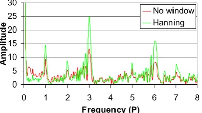
[image:2.595.77.274.170.283.2]No window Hanning
Figure 2: FFT for rear blade thrust loading
during normal contra-rotating operation.
0 5 10 15 20 25 30
0 1 2 3 4 5 6 7 8
Frequency (P)
A
m
p
li
tu
d
e
[image:2.595.77.276.348.459.2]No window Hanning
Figure 3: FFT of blade thrust loading for frame
mounted single rotor.
0 2 4 6 8 10
0 1 2 3 4 5 6 7 8
Frequency (P)
A
m
p
li
tu
d
e
[image:2.595.76.277.512.626.2]No window Hanning
Figure 4: FFT of blade edge loading (observed
in power train) for frame mounted single rotor.
Time-series data from strain gauge measurements have been collected for scrutiny from tank tests and prototype sea trials. Figures 2 - 4 illustrate the Fast Fourier Transforms (FFTs) of the recorded forces and clearly illustrate the principal frequency components on the blades when operating as a single rotor frame mounted unit, and as a two rotor
contra-rotating unit. (P refers to multiples of the rear
rotor rotational frequency.)
A comparison of Figures 2 and 3 reveals that frequency P1 is present showing some instrument crossover for blade gravity effects and a slight blade misalignment for thrust. P2 is due to a stabilising vertical turbine tail as seen in Figure 1 which was found during testing to be unnecessary. The normal contra-rotating operation (Figure 2) differs significantly from single rotor operation in Figure 3 where P3 and P6 magnitudes are observed. P3 is due to the 3-pronged frame upstream and P6 is a combination of this and the stalled 3 blades of rotor 1. The edgewise FFT plot in Figure 4 is for the same test-run as Figure 2, and shows that there is some interference in the output torque caused by interference from the supporting frame (P3 and P6 again). This diminishes the electrical output quality as compared to a freely ‘flying’ turbine further supporting the philosophy of the contra-rotating design.
3 Mooring Arrangements
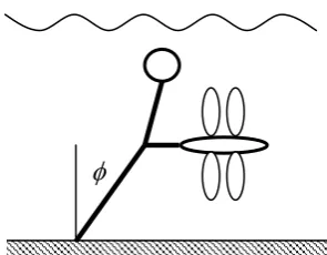
The steady (or quasi-steady) load conditions for a single-point mooring are relatively straight forward. With direct bottom mounting (Figure 5), excess buoyancy in the turbine nacelle maintains turbine depth of immersion within a certain range. The cable takes up a position
such that
B FD =
φ
tan , where B is the net
buoyancy force and FD is the drag force on the turbine.
B
F
DT
φ
Figure 5: Bottom-moored, buoyant turbine
showing free body diagram at the cable attachment point.
[image:2.595.332.492.543.685.2]optimum conditions is 8/9, so FD can be very
large. It follows that B must be correspondingly
large; if not, an extremely long cable is required and the “footprint” of the system when the flow changes direction becomes excessive.
Control of depth is however not good: if the turbine drag coefficient remains constant,
where V is the current velocity.
Therefore and φ will vary greatly during the tidal cycle. A small measure of self-regulation comes from the fact that V is likely to
reduce as the turbine goes deeper, but the general trends are clear. At extreme values of V
the power output from the turbine might be limited to some rated value and this would tend to reduce the drag coefficient and hence FD, but only by a modest amount.
2
V
F
D
∝
2
tan
φ
∝
V
The second option is to “fly” the turbine from a tensioned cable (Figure 6).
[image:3.595.315.518.167.273.2]
Figure 6: Neutrally-buoyant turbine on a
tensioned cable.
Here the turbine itself would have near-neutral buoyancy with the excess provided by the tensioning float. For the lower part of the cable, static analysis again reduces to the equation
B F
D =
φ
tan , but in this case FD is the
summation of the drag forces on the turbine and float; the latter may be quite substantial. It can be reduced significantly by placing the float on the surface, if excitation by waves is not a problem.
The intention with this configuration would be to operate at small values of φ by building in greater excess buoyancy. Variations in operating depth with current velocity V would
then be significantly reduced.
The effects of scale may have an influence on the choice of mooring configuration. Drag forces rise approximately with the square of the linear dimension, whereas buoyancy increases with the cube. Figure 7 illustrates this with regard to a spherical surface float or floatation chamber.
0 0.5 1 1.5 2 2.5 3
0 50 100 150
Turbine Rating (kW)
F
lo
a
t
D
ia
m
e
te
r
(m
[image:3.595.84.232.367.482.2])
Figure 7: Float diameter versus turbine rating
(Vtide-max = 2.5ms-1).
The active material weight of the Permanent Magnet Generator (PMG) is likely to be the most significant part-mass of the turbine. The PMG mass may be calculated by rearranging equation (1): where J is the conductor maximum
current density, rI is the inner core radius, rO is the outer core radius, B is the average flux
density in the winding, n is the rotational speed,
and a is the winding axial thickness.
φ
2(
2 2)
.
.
.
4
J
r
IB
n
a
r
Or
IP
=
π
−
(1)rO was set to be √3 rI thus optimising the power
for a given outside diameter and loading [4]. This is unlikely to be an optimal mechanical or economic design, but allows sufficient radius information to estimate the weight of a PMG. This was added to the calculation for buoyancy used to produce Figure 7.
As Figure 7 illustrates, at large scales it becomes increasingly possible to incorporate the relatively decreasing buoyancy volume into the turbine nacelle, and the simple mooring depicted in Figure 5 becomes feasible. At small scales, auxiliary buoyancy is likely to be required (Figure 6).
possible including motoring a main rotor or the use of modified marine thrusters to provide yaw control.
Another issue is cable twist: repeated circular motions of the device about its tethering point would eventually damage the electrical power cable, which must necessarily follow the route of the main cable to the sea bed. The aforementioned yaw mechanism could provide an unwind function, or a slip-ring style electrical coupling could be employed – the life-cycle duty of such a mechanism being very small compared to that used in high-speed machinery.
Yet another issue is stability in turbulent flows: tests by the authors on small models in flumes (only qualitative so far) indicate that the shape of the nacelle may be an important factor. With some shapes, oscillations in yaw or pitch seem to occur despite the large self-aligning effect of the drag force on the rotor itself.
4 Small turbine for sea trials
A small contra-rotating turbine is presently being prepared for sea trials. These are intended to shed light on a number of issues:
• the performance of a complete contra-rotating power train;
• the production of electricity from a submerged generator;
[image:4.595.71.288.503.677.2]• and the stability of the complete system on a single-point mooring.
Figure 8: Rendering of miniCoRMaT test-bed.
The turbine uses a direct-drive generator, resulting in a large nacelle diameter. There was also a demand for a reasonably high rotational speed, which imposed limits on overall rotor
diameter. The result was a turbine with hub diameter 0.43m and overall diameter 0.92m. The complete miniCoRMaT turbine is illustrated as a cut-away drawing in Figure 8.
Despite the bulky nacelle, it was found to be difficult at this scale to go much beyond neutral buoyancy and a tensioned cable with auxiliary float (Figure 6) is to be employed in the trials.
It has been recommended that the generator diameter should not be greater than 10% of the rotor diameter for wind turbines [4], however it is presently unknown whether this holds for tidal turbines. Options exist to reduce the diameter of the generator:
• Several axial generator units may be connected in series on the same frame, • The electrical output may be generated
at a lower frequency and converted to that required, although core copper losses increase significantly at very low frequencies [5]
5 Direct Drive Generator
The relatively slow prime mover rotational speed of a tidal turbine (TSR from Figure 10 and at Vtide_max of 2.5ms-1) necessitates a gearbox to increase the speed suitably for a common four-pole generator. Another option is a direct drive generator with a large number of poles. This has the distinct advantages of: a higher overall power take off efficiency of typically 90% near rated load [6] compared to around 85% for a costly multi-stage high torque gearbox (4-stage efficiency of 94%) and generator (90%) combination [7]; greater reliability; and a diminished maintenance requirement.
Contra-rotating Generator
The manufactured direct drive generator has an axial magnetic field created by 24 Neodymium-Iron-Boron (Nd-Fe-B) N50 grade permanent magnets distributed on the 2 rotors making up 12 magnetic poles, and sandwiching the stator which contains 9 copper windings. Nd-Fe-B magnets have vastly superior magnetic properties over traditional Ferrite magnets. The remanence flux density Bτ of the chosen
magnets is 1.42T. The maximum operating temperature (150 oC) of Nd-Fe-B magnets is unlikely to be an issue in a submerged tidal generator. Figure 9 is a CAD drawing of the generator showing the critical components. Spine
Buoyant Cone Contra-rotating
Blades Buoyant
Figure 9: CAD rendering of contra-rotating axial flux generator.
The axial-flux generator is configured to provide a 3-phase electrical output. This is converted to DC via a 3-phase rectifier. The energy may therefore be efficiently transmitted underwater and inverted at the grid end, or in this experimental case, fed into a resistive dumped load by a Pulse Width Modulated (PWM) driven Insulated Gate Bipolar Transistor (IGBT) allowing the turbine microcontroller to regulate the overall turbine speed and attain maximum Cp throughout the tidal cycle. The contra-rotating prime mover torque balance critical to maintaining the zero reactive torque and thus providing turbine hydrodynamic stability is provided inherently by the magnetic flux linkage across the stator-rotor air gap.
In addition it was decided to experiment with a submersible generator, that is, the rotors and stator both operate in sea-water. Although the magnetic properties of sea-water and air are not significantly different, the electrical insulating properties and corrosive abilities certainly are. The rotors and nickel coated permanent magnets are therefore coated in a hard wearing polymer to provide corrosion protection. The stator is constructed from polyurethane resin into which the copper coils are hermetically sealed with glands allowing the electrical output cables to exit the generator. The advantages of a generator open to seawater are:
• ease of construction,
• generator/nacelle casing leaks are non issues,
• cooling is naturally provided, • no complex sealing requirements, • no large diameter seal friction.
Possible drawbacks are:
• lowered efficiency due to the hydro-dynamic effects of rotating parts, • marine growth on exposed components.
The first drawback is partly mitigated by the relatively low rotational speeds and the hydrodynamically efficient design of the exposed parts. Marine growth may be mitigated against by the speed of rotation, the use of anti-fouling compounds and a mechanical ‘wiper’ system on the active generator surfaces.
6 Prime Mover and Hydrodynamics
It was decided to use blades from a turbine used in earlier tank tests [9], modified slightly to suit the specified dimensions. As in previous designs, 3 blades are fitted to the upstream rotor and 4 blades downstream. Blade element modelling was employed to determine the optimum blade pitch angles. Performance of this machine was compromised to some extent by the fact that the blade chord and pitch distributions had originally been optimised to suit a different set of parameters. Predictions of power and thrust coefficients (CPand Ct) for the
complete 2-rotor machine are given in Figure 10.
0 0.1 0.2 0.3 0.4 0.5 0.6
2 4 6 8 1
Tip speed ratio
0
Cp Ct
Figure 10: Performance predictions for turbine
to be used in full system sea trials.
A good peak hydrodynamic efficiency is not essential to achieving the aims of the test programme. The tip speed ratio at which peak Spine
Ne-Fe-B Magnets
Rotors
Prime Mover 1
Stator
Prime Mover 2
[image:5.595.319.512.449.671.2]CP is achieved reflects the geometric limitations
imposed on the design; a higher value would perhaps have been desirable.
7 Conclusion
The described miniCoRMaT tidal system has been manufactured and will undergo sea trails off South West Scotland during July 2008. This will substantiate the specific claims made, namely:
1) the feasibility of using a single-point mooring system with additional buoyancy for a tidal turbine,
2) the feasibility of a simple submersible direct drive PMG,
3) the comparative economic viability of this system versus existing more conventional systems.
8 References
[1] Myers L and Bahaj A J. Wake studies of a 1/30th scale horizontal axis marine turbine. Ocean Engineering 34 (2007), pp 758-762.
[2] Kim H W and Brown R E. Coaxial rotor performance and wake dynamics in steady and manoeuvring flight. American Helicopter Society 62nd Forum (2006), Phoenix, Arizona, USA.
[3] Spooner E, Chalmers B J. ‘TORUS’: A Slotless, Toroidal-stator, permanent magnet generator, IEE Proceedings B, Vol. 139, pp. 497-506, November 1992.
[4] Soderlund L, Eriksson J T, Salonen J, Vihriala H, Perala R. A Permanent-Magnet Generator for Wind Power Applications, IEEE Transactions on Magnetics, Vol. 32, No. 4, July 1996.
[5] Segergren E, Nilsson K, Leijon M. Frequency Optimisation with Respect to Weight and Electrical Efficiency for Direct Drive Underwater Power Generator. IEEE Journal of Oceanic Engineering, November 2004.
[6] Nilsson K, Segergren E, Sundberg J, Sjostedt E, Leijon M. Converting Kinetic Energy in Small Watercourses Using Direct Drive Generators. Proceedings of OMAE04 23rd International Conference on Offshore
Mechanics and Arctic Engineering (2004), Vancouver, British Columbia, Canada.
[8] Cotrell J. A. Preliminary Evaluation of a Multiple-Generator Drivetrain Configuration for Wind Turbines, 21st American Society of Mechanical Engineers (ASME) Wind Energy Symposium, Reno, Nevada, January, 2002.