Int. J. Electrochem. Sci., 13 (2018) 8775 – 8783, doi: 10.20964/2018.09.23
International Journal of
ELECTROCHEMICAL
SCIENCE
www.electrochemsci.orgFabrication of MnOx/MWCNTs-GC Nanocatalyst for Oxygen
Evolution Reaction
Islam M. Al-Akraa*, Yaser M. Asal, Amr M. Arafa
Department of Chemical Engineering, Faculty of Engineering, The British University in Egypt, Cairo 11837, Egypt
*
E-mail: islam.ahmed@bue.edu.eg; islam0886@yahoo.com
Received: 13 April 2018 / Accepted: 2 June 2018 / Published: 5 August 2018
Manganese oxide (MnOx) and multiwalled carbon nanotubes (MWCNTs) are intended to modify the GC electrode for oxygen evolution reaction (OER). Optimization of MnOx loading is carried out and the deposition of 55 cycles was sufficient to obtain the highest activity toward OER. The stability of the catalyst is enhanced by the addition of MWCNTs. As a result, an amount of 22 kWh/Kg of O2 of energy is saved. Several techniques including cyclic voltammetry, linear sweep voltammetry, chronoamperometry, chronopotentiometry, field-emission scanning electron microscopy, and energy dispersive X-ray spectroscopy will be combined to track the catalyst activity and to determine its morphology and composition.
Keywords: Oxygen evolution reaction; Water electrolysis; Manganese oxide; Carbon nanotubes.
1. INTRODUCTION
We can now declare that environmental issues and those related to energy supply and demand have become a major challenge facing the whole world because of the growing fears of the limited reserves of fossil fuels in addition to its polluting impact on the environment. Preference and attention have been shifted towards the clean renewable sources, especially in the global communities of scientific research. Among these clean energy sources rises the hydrogen as the most reliable secondary energy source, where the production of hydrogen in sufficient quantities is mainly depending on electro-catalytic water splitting technique, which not only is considered as renewable source of electricity, but also a sustainable hydrogen producer [1, 2].
anode [2, 3]. The use of electrolyzed water in industrial applications for hydrogen production is limited because of the slow kinetics of the process of OER, whereas the execution of high performance, cost-effective OER is highly preferred [1, 4, 5]. To overcome this limitation several attempts have been carried out using metal oxide, metal or modified platinum [6, 7], gold [8], nickel [9, 10], cobalt [10-13], Iridium [14, 15], ruthenium [7, 16-18], and rhodium [19] surfaces. However, unluckily, electrode material decomposition and the parallel oxidation pathways associated with OER have restricted the choice of appropriate anodic materials for efficient water electrolyzers.
Nano-sized materials show distinctive chemical and physical properties in comparison with their bulk ones. Not only in the geometry, which is inferred from the unique morphology and the large surface area to volume ratio, but also in the electronic properties which may be changed with the size shrinkage [20, 21]. This has fascinatingly initiated great potential applications in catalysis [20, 22, 23], chemical and biochemical sensing [20, 23-29], and biological imaging [20, 26-30]. In this regard, electrodes modified with nanostructures have been suggested, and that was promising in increasing the activity and stability toward OER [31].
In this investigation, OER will be tracked at manganese oxide (MnOx)-modified glassy carbon (GC) electrode (MnOx/GC), optimization of the loading is carried out, the influence of modifying the GC electrode with multiwalled carbon nanotubes (MWCNTs) prior to MnOx deposition (MnOx/MWCNTs-GC) on its stability toward OER will be monitored, and the catalyst's morphology will be imaged using field emission scanning electron microscopy (FE-SEM).
2. EXPERIMENTAL
A mechanically-cleaned and polished, with fine alumina powder, GC electrode (d = 5.0 mm) purchased from ALS, Japan was served as the working electrode. A saturated calomel electrode (SCE) and a spiral Pt wire were used as the reference and counter electrodes, respectively.
The chemicals used in this investigation were of high purity and used without further purification. Solutions were prepared using doubly distilled water.
The electrodeposition of MnOx on the GC electrode is carried out by cycling the potential between 0 and 0.4 V for several cycles at 50 mV s−1 in 0.1 M Na2SO4 containing 0.1 M Mn(CH3COO)2.
To modify the GC surface with MWCNTs, a 10 mg MWCNTs was initially dispersed in 1 ml aliquots of 5% Nafion/ethanol and sonicated for 1 h. On the GC electrode, 10 µL of the suspension is applied evenly and the ethanol was allowed to evaporate at room temperature for 1 h. The modified electrode was then washed with doubly distilled water.
The electrochemical measurements were performed at room temperature (25±1 oC) in a conventional two-compartment three-electrode glass cell using a Bio-Logic SAS potentiostat (model SP-150) operated with EC-Lab software.
A field emission scanning electron microscope (FE-SEM, QUANTA FEG 250) coupled with an energy dispersive X-ray spectrometer (EDS) unit was employed to evaluate the electrode’s morphology and composition.
3. RESULTS AND DISCUSSION
3.1. Electrochemical and Material characterization
Figure 1 shows cyclic voltammograms CVs obtained at (a-g) MnOx/GC with several MnOx loading cycles and (h) MnOx (55 cycles) MWCNTs-GC modified electrodes measured in 0.1 M NaOH at a potential scan rate of 100 mVs-1. The measurements are performed in an alkaline solution to track the redox behavior of the electrodeposited MnOx at the GC electrodes [32]. A redox couple is observed in all cases which continuously increasing with increasing the number of loading cycles which assigned to the redox transformation between lower and higher oxidation states of Mn (i.e., MnOOH/MnO2) [33].
E
/ V vs. SCE
-1.0 -0.8 -0.6 -0.4 -0.2 0.0 0.2 0.4 0.6
I
/ mA
-0.3 -0.2 -0.1 0.0 0.1 0.2 0.3 0.4 0.5
(a) MnOx (5 cycles)/GC
(b) MnOx (10 cycles)/GC
(c) MnOx (20 cycles)/GC (d) MnOx (30 cycles)/GC (e) MnOx (40 cycles)/GC (f) MnOx (50 cycles)/GC
(g) MnOx (55 cycles)/GC
(h) MnOx (55 cycles)/MWCNTs-GC
Figure 1. CVs obtained at (a-g) MnOx/GC with several MnOx loading cycles and (h) MnOx (55 cycles)/MWCNTs-GC modified electrodes measured in 0.1 M NaOH at a potential scan rate of 100 mVs-1.
[image:3.596.89.504.349.653.2]
The EDS analysis in Fig. 3 confirmed the deposition of all ingredients of the modified catalyst and assisted in calculation of their relative ratios.
Figure 2. FE-SEM micrographs of the MnOx (55 cycle)/GC and MnOx (55 cycle)/MWCNTs-GC modified electrodes.
Figure 3. EDS analysis of the MnOx (55 cycle)/GC modified electrode.
3.2. Electrocatalytic activity toward OER
The OER is an anodic process, which occurs at most of the metal electrode surfaces at potentials adequately anodic to permit the formation of various kinds of oxides. Figure 4 shows the
[image:4.596.46.553.129.362.2] [image:4.596.52.537.427.661.2]
linear sweep voltammograms (LSVs) of the MnOx/GC and MnOx/MWCNTs-GC modified electrodes measured in 0.1 M NaOH solution at a potential scan rate of 50 mV s−1.
For anodic reactions, as in case of OER, the lower the onset potential (the potential at which the reaction starts, Eonset) the electrode has, the better the electrocatalytic enhancement the electrode exhibits. This is because the negative shift in the onset potential will be echoed in a power saving which is eventually targeted for industrial applications. In fact, the Eonset for OER at the bare GC electrode was ca. 1.5 V (Fig. 4i). Interestingly, as MnOx was continuously loaded at the GC and MWCNTs-GC surfaces, the Eonset decreased also in a continuous way until reaching 55 cycles of deposition which was the optimum deposition condition (Fig.4 a-h). The Eonset, negative shift in the Eonset compared to that of the bare GC electrode (ǀEonset − Eonset (bare GC)ǀ) at 0.3 mA, and the corresponding energy saving values could be calculated and summarized in table 1 [34].
E / V vs. SCE
0.0
0.2
0.4
0.6
0.8
1.0
1.2
1.4
1.6
I
/ mA
0.0
0.5
1.0
1.5
2.0
2.5
(a) MnOx (5 cycles)/GC (b) MnOx (10 cycles)/GC
(c) MnOx (20 cycles)/GC
(d) MnOx (30 cycles)/GC
(e) MnOx (40 cycles)/GC
(f) MnOx (50 cycles)/GC
(g) MnOx (55 cycles)/GC
(h) MnOx (55 cycles)/MWCNTs-GC (i) bare GC
Figure 4. LSVs obtained at (a-g) MnOx/GC with several MnOx loading cycles, (h) MnOx (55 cycles)/MWCNTs-GC, and (i) bare GC electrodes measured in 0.1 M NaOH. Potential scan rate: 50 mVs-1.
The unique electrocatalytic activity observed at MnOx-modified GC electrodes for OER can be clarified considering the general mechanism for the OER that has been frequently considered in alkaline media [35-37] :
[image:5.596.86.512.275.603.2]
2 MO → 2M + O2 (4)
[image:6.596.40.568.211.396.2]Here M is the metal active surface site. The rate determining step is often assigned to the adsorption and the initial charge transfer, i.e., Reaction 1 [34, 38]. Herein, the high catalytic activity is thought to arise from the redox mediation by MnOx [38]. This can, definitely, facilitate the charge transfer at the rate determining step (Reaction 1), and will definitely catalyze OER.
Table 1. A summary of the Eonset, negative shift in the Eonset compared to that of the bare GC electrode (ǀEonset - Eonset (bare GC)ǀ) at 0.3 mA, and the corresponding energy saving values.
Electrode Eonset, V ǀEonset - Eonset (bare GC)ǀ, V Power saving, kWh/Kg
O2
bare GC 1.50 --- ---
MnOx (5 cycles)/GC 0.89 0.61 16.3
MnOx (10 cycles)/GC 0.85 0.65 17.4
MnOx (20 cycles)/GC 0.79 0.71 19.0
MnOx (30 cycles)/GC 0.75 0.75 20.1
MnOx (40 cycles)/GC 0.72 0.78 20.9
MnOx (50 cycles)/GC 0.71 0.79 21.2
MnOx (55 cycles)/GC 0.70 0.80 21.4
MnOx (55 cycles)/MWCNTs-GC 0.68 0.82 22.0
3.3. Stability toward OER
t / s
0 300 600 900 1200 1500 1800
I
/ mA
0.0 0.2 0.4 0.6 0.8 1.0
(a) MnOx (55 cycles)/GC
(b) MnOx (55 cycles)/MWCNTs-GC
[image:6.596.115.489.460.720.2]
Figure 6. E-t curves of the MnOx (55 cycle)/GC and MnOx (55 cycle)/MWCNTs-GC modified electrodes measured in 0.1 M NaOH at 0.2 mA.
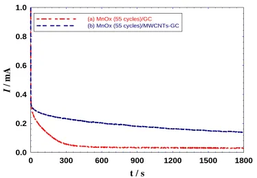
Stability of the MnOx (55 cycles)/GC and MnOx (55 cycles)/MWCNTs-GC modified electrodes has been identified using chronoamperometry (recording current as a function of time at 0.8 V, i-t) and chronopotentiometry (recording potential as a function of time at 0.2 mA, E-t). Figure 5 shows the i-t curves for the MnOx (55 cycles)/GC (Fig. 5a) and MnOx (55 cycles)/MWCNTs-GC modified electrodes (Fig. 5b). Although it acquired a high activity toward OER, the stability of the MnOx (55 cycles)/GC electrode was not good enough as indicated from the fast current decay during continuous electrolysis. Fortunately, using MWCNTs, in case of the MnOx (55 cycles)/MWCNTs-GC electrode, the stability is enhanced to a great extent where the current decay was no longer being fast.
Alternatively, Fig. 6 shows the E-t curves for the MnOx (55 cycles)/GC (Fig. 6a) and MnOx (55 cycles)/MWCNTs-GC modified electrodes (Fig. 6b). Again, the MnOx (55 cycles)/MWCNTs-GC acquired a lower potential vs. time toward OER which strongly agrees with the data in Fig. 5. It is expected that the nature of MWCNTs is beyond this improvement in the catalyst stability.
4. CONCLUSION
[image:7.596.116.477.79.349.2]
enhancement was thought to arise from the redox mediation by MnOx which facilitated the charge transfer at the rate determining step in addition to the high stable nature of MWCNTs.
References
1. J. Sun, H. Li, Y. Huang and Z. Zhuang, Mater. Lett, 223 (2018) 246.
2. C. Coutanceau, S. Baranton and T. Audichon, Hydrogen Electrochemical Production, Academic Press, 2018, p. 17.
3. M. Tahir, L. Pan, F. Idrees, X. Zhang, L. Wang, J.-J. Zou and Z.L. Wang, Nano Energy, 37 (2017) 136.
4. F.e. Chakik, M. Kaddami and M. Mikou, Int. J. Hydrogen Energy, 42 (2017) 25550. 5. J. Chi and H. Yu, Chinese J. Catal, 39 (2018) 390.
6. V.I. Birss, A. Damjanovic and P.G. Hudson, J. Electrochem. Soc., 133 (1986) 1621. 7. V.I. Birss and A. Damjanovic, J. Electrochem. Soc., 134 (1987) 113.
8. S. Barnartt, J. Electrochem. Soc., 106 (1959) 722.
9. R.N. Singh, T. Sharma and A. Singh, New Mater. Electrochem. Systems, 10 (2007) 105. 10.C. Bocca, A. Barbucci, M. Delucchi and G. Cerisola, Int. J. Hydrogen Energy, 24 (1999) 21. 11.A. Nidola, Mater. Chem. Phys., 22 (1989) 183.
12.T.-C. Wen and H.-M. Kang, Electrochim. Acta, 43 (1998) 1729.
13.Y.-S. Lee, C.-C. Hu and T.-C. Wen, J. Electrochem. Soc., 143 (1996) 1218. 14.E. Guerrini, H. Chen and S. Trasatti, J. Solid State Electrochem., 11 (2007) 939.
15.S. Hackwood, L.M. Schiavone, W.C. Dautremont-Smith and G. Beni, J. Electrochem. Soc., 128 (1981) 2569.
16.H. Ma, C. Liu, J. Liao, Y. Su, X. Xue and W. Xing, J. Mol. Catal. A: Chem., 247 (2006) 7. 17.R. Koetz and S. Stucki, J. Electrochem. Soc., 132 (1985) 103.
18.C. Iwakura, K. Hirao and H. Tamura, Electrochim. Acta, 22 (1977) 329. 19.E.J.M. O'Sullivan and L.D. Burke, J. Electrochem. Soc., 137 (1990) 466. 20.P. Kalimuthu and S. John, J. Electroanal. Chem., 617 (2008) 164. 21.A. Alivisatos, Science, 271 (1996) 933.
22.A.D. Daniel MC, Chem. Rev., 104 (2004) 293.
23.C. Burda, X. Chen, R. Narayanan and M. El-Sayed, Chem. Rev., 105 (2005) 1025. 24.K. Aslan, J. Lakowicz and C. Geddes, Anal. Chem., 77 (2005) 2007.
25.R. Elghanian, J. Storhoff, R. Mucic, R. Letsinger and C. Mirkin, Science, 277 (1997) 1078. 26.D. Stuart, A. Haes, C. Yonzon, E. Hicks and R. Duyne, IEEE Proc. Nanobiotechnol., 152 (2005)
13.
27.J. West and N. Halas, Annu. Rev. Biomed Eng., 5 (2003) 285. 28.S. Bharathi, M. Nagami and O. Lev, Langmuir, 17 (2001) 2602. 29.B. Jena and C. Raj, Anal. Chem., 78 (2006) 6332.
30.G. Maduraiveeran and R. Ramaraj, J. Electroanal. Chem., 608 (2007) 52.
31.I.M. Sadiek, A.M. Mohammad, M.E. El-Shakre and M.S. El-Deab, Int. J. Hydrogen Energy, 37 (2012) 68.
32.I.M. Sadiek, A.M. Mohammad, M.E. El-Shakre, M.I. Awad, M.S. El-Deab and B.E. El-Anadouli, Int. J. Electrochem. Sci., 7 (2012) 3350.
33.M.S. El-Deab, Int. J. Electrochem. Sci., 4 (2009) 1329.
34.I.M. Al-Akraa, A.M. Mohammad, M.S. El-Deab and B.E. El-Anadouli, Arabian J. Chem., 10 (2017) 877.
35.A.C. Ferreria, E.R. Gonzalez, E.A. ticianelli, L.A. Avaca and B. Matvienko, J. Appl. Electrochem., 18 (1988) 894.
37.Y. Matsumoto, S. Yamada, T. Nishida and E. Sato, J. Electrochem. Soc., 127 (1980) 2360. 38.A.M. Mohammad, M.I. Awad, M.S. El-Deab, T. Okajima and T. Ohsaka, Electrochim. Acta, 53
(2008) 4351.