INTERNATIONAL CONFERENCE ON ENGINEERING DESIGN, ICED’07
28 - 31 AUGUST 2007, CITE DES SCIENCES ET DE L'INDUSTRIE, PARIS, FRANCE
REAL T I M E RESOU RCE SCH EDU LI N G WI T H I N A
DI ST RI BU T ED COLLABORAT I V E DESI GN
EN V I RON M EN T
R.I. Whitfield1, A.H.B. Duffy1, and G. Coates2 1
Department of Design Manufacture and Engineering Management, University of Strathclyde, 75 Montrose Street, Glasgow, G1 1XJ.
2
School of Engineering, Durham University, South Road, Durham, DH1 3LE.
ABSTRACT
Operational design co-ordination is provided by a Virtual Integration Platform (VIP) that is capable of scheduling and allocating design activities to organisationally and geographically distributed designers. To achieve this, the platform consists of a number of components that contribute to the engineering management and co-ordination of data, resources, activities, requirements and processes. The information required to schedule and allocate activities to designers is defined in terms of: the designers’ capability to perform particular design activities; commitment in terms of the design activities that it is currently performing, and capacity to perform more than one design activity at the same time as well as the effect of increased capacity on capability. Previous approaches have been developed by the authors to automatically allocate resources to activities [1-3], however these approaches have generally been applied either within the context of real-time allocation of computational resources using automated design tools, or in the planning of human resources within future design projects and not for the real-time allocation of activities to a combination of human and computational resources. The procedure presented here is based upon this previous research and involves: the determination of the design activities that need to be undertaken on the basis of the goals that need to be achieved; identification of the resources that can undertake these design activities; and, the use of a genetic algorithm to optimally allocate the activities to the resources. Since the focus of the procedure is toward the real-time allocation of design activities to designers, additional human issues with respect to scheduling are considered. These human issues aspects include: consideration of the improvement in performance as a result of the experience gained from undertaking the activity; provision of a training period to allow inexperienced designers the opportunity to improve their performance without their performance being assessed; and the course of action to take when a designer is either unwilling or unable to perform an activity.
Keywords: Resource management, activity scheduling, distributed design, real time operational design co-ordination
1 I N T RODU CT I ON
The VIP provides long term benefit to the maritime industry as a whole through the embedding of high technology into the fabric of designing, building and operating the ships of the future. To achieve this required critical technologies of ship systems (such as evacuation and damage stability simulations) to be integrated to ensure the design of safe and reliable transportation of goods and people.
approximately three months. The processes created to manage this design consisted of 34 activities across six life-phases of the design of a ROPAX. Typically these activities would be enacted within a single shipyard, however the focus of the VRShips project was to allow the design process (and consequently the activities) to be distributed across Europe to take advantage of the expertise that is available. Effective management and enactment of these distributed processes was achieved through the development of the Process Control Tool (PCT) and the linking of this tool to the other components within the VIP.
The PCT allows the definition, management and enactment of life-phase design processes, the definition and scheduling of human and computational resources, and the definition and tracking of product based requirements. Process models consisting of statically defined sequences of inter-connected activities may be created, and through the use of the VIP these activities may be mapped to resources to define capability. Real-time enactment of the processes is enabled through the allocation of activities to designers on the basis of their capability irrespective of where they are organisationally or geographically located. The need for such a tool to provide a formalised approach for the co-ordination of processes and resources is to avoid chaotic behaviour [4], and to ensure that the right activity is performed for the right reason, at the right time [5, 6]. Since the VIP provides an automatic mapping between tools, activities and designers, the PCT is able to reason about the activities that need to be undertaken, the appropriate designers that can undertake them, and the tools to use within the activities. The PCT provides elements of the goal result model, the activity/plan model, and the resources structure within the Design Co-ordination Framework [5].
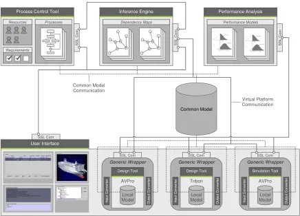
Consideration was given for the development of the VIP to allow for systematic integration, management and testing of the various technologies to ensure overall design optimisation and product performance, while addressing all the life phases of the ship. The virtual platform consists of: the integration framework; the common model; the virtual environment; the inference engine; the process control tool; the simulation engine; and the performance modelling tool. The process control tool interacts with these components in the following way:
• Integration framework. The integration framework delivers a strategy and architecture to
guide the integration activities of the common model, virtual environment, inference engine, PCT, design and simulation tools, and performance-modelling tool. To enable this, a
communication module was developed enabling XML based messages to be created, sent and processed securely between each of the VIP components.
• Common model. The common model is a database that provides a consistent representation of
the data defining the ship systems, and holds the basic (and common) geometry and information required by each of the integrated design and simulation tools irrespective of the tools’ native data formats. XML was used as the language to represent the ship-product data, as well as the models of the inference engine and PCT.
• Virtual environment. The virtual environment is the interface that enabled designers to interact with the VIP. The virtual environment provides functionality to enable: multiple designers; configuration and use of design and simulation tools; access and visualisation of the common model; querying of data consistency status; enactment of processes, and use of the performance-modelling tool. The virtual environment and the PCT have many interactions to manage logging onto the platform, allocation of activities, notification of activity completion, management of designers, requirements and processes, and communication between designers.
• Inference engine. The virtual environment enables designers to communicate and share product
User Interface Common Model Generic Wrapper Simulation Tool AVPro Local Model Input C o nv erter Output C on v er ter SSL Com Generic Wrapper Design Tool Tribon Local Model Input C o nv erter Output C on v er ter SSL Com Generic Wrapper Design Tool AVPro Local Model Input C o nv erter Output C on v er ter SSL Com
Process Control Tool
[image:3.595.79.515.55.369.2]Resources Requirements Processes SSL Com SSL Com Inference Engine Dependency Maps SSL Com Performance Analysis Performance Models SS L C o m Common Model Communication Virtual Platform Communication
Figure 1. VIP virtual platform components.
Two approaches were developed within the PCT for the allocation of activities to designers which form the basis for the research within this paper:
• Local allocation. The approach considers each activity individually prior to enactment and schedules the most appropriate resource on a basis of time for purely computational resources, as well as training and experience for designers.
• Global allocation. The approach considers all of the activities that are planned for enactment and schedules the most appropriate resources for each activity on the basis of time only. The hypothesis is that that global approach could result with a reduction in time taken to enact the process assuming that it has selected the optimum mapping between resources and activities. Section 2 provides an overview of the PCT, whilst Section 3 describes the approaches used for the scheduling of resources, and enactment of activities.
2 PROCESS CON T ROL T OOL OV ERV I EW
The VIP provides co-ordination at both an activity and data level by the PCT and inference engine respectively. The PCT ensures that the right thing is done at the right time for the right reason, whereas the inference engine ensures that the right thing is done with the right information. The aim of these two types of co-ordination is to avoid chaotic behaviour.
2.1 Process management
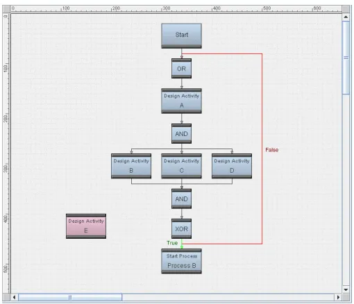
[image:4.595.170.425.266.485.2]The PCT is capable of managing the construction and enactment of multiple simultaneous processes. The activities within the processes, and the processes themselves may be defined at any level of abstraction and may be used to represent any type of engineering design problem that both requires operational co-ordination, and is based on well-established processes such as the design of large made-to-order products for example. The design processes within the shipbuilding industry are typically well-established and static in nature, and are particularly appropriate for this application. Activities have been defined to provide functionality for: scheduling (default duration and expected start times, resource requirements); process control (connectivity with other activities), and rendering within the user interface (size, colour, location). The use of Object-Oriented Design principles within the development of the PCT enabled the definition of a number of different types of activities that have various process control functionality, as well as enabling additional types of activity to be created in the future to provide alternative functionality or connectivity with the VIP. Inter-connectivity between activities is defined to indicate the sequence that the activities will be enacted within the process – Figure 2.
False
• past (activities that have been completed)
True
Figure 2. Control flow example using different types of activities.
Processes can be can be started, paused, continued, and stopped through interaction with either the virtual environment or inference engine components of the VIP, or through direct interaction with the user interface of the PCT. Since the activities may be dynamically enacted, it is impossible to predict in advance which activities would be running. It is also possible that multiple activities within the same process may be running at the same point in time. The PCT therefore provides management for the activities within a process on the basis of their state of enactment and uses this information to establish whether an activity can be enacted on the basis of the state of the preceding activities as follows:
• present (activities that are currently being enacted)
• future (activities that will be enacted at some point in the future)
• pending (activities that for some reason cannot currently be enacted).
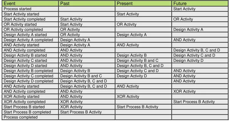
process enactment is presented within Table 1. The process is considered to be complete when the state of all of the activities is “past”.
[image:5.595.96.497.386.600.2]As previously mentioned, the processes defined within the PCT are static in nature – the activities and connections within them do not change and would be synonymous with a work-flow model. The activity allocation is however determined dynamically using information relating to the designers’ availability and capabilities. When a designer logs onto the VIP, information regarding the designer in terms of their location is sent to the PCT, which changes the availability status of the designer (as a resource). Since the focus of the VIP was for the application of the distributed co-ordinated design of a ROPAX vessel (or other large made-to-order products), the associated processes are usually well established and static in nature with respect to the definition of the activities and their relationships. Whilst the processes may be static in nature, the actual design work that is undertaken within the processes may differ depending upon the vessel being designed, the customer requirements, or the tools available for example. The PCT does not dictate the specific details of the design activity that needs to be undertaken, since the activities defined within the PCT are generally defined at a level of abstraction higher than this detailed level. The PCT does however allow the inclusion of additional guidance to be propagated through the process. This guidance may for example be provided by a designer early with the process to provide specific details of what has been changed, such that designers performing later activities may take action on the basis of this guidance. This approach provides a general static process definition prior to process enactment that provides high level control support, with the dynamic tailorability through the addition of design guidance during enactment to make the process flexible in terms of the specific design requirements. The action that the scheduled designer chooses to undertake when an activity is allocated is entirely unconstrained by the PCT. The designer is therefore free to interpret the guidance received from the PCT and undertake the activity in whichever way they consider appropriate.
Table 1. Activity state change example for enactment of process within Figure 2.
Event Past Present Future
Process started Start Activity
Start Activity started Start Activity
Start Activity completed Start Activity OR Activity OR Activity started Start Activity OR Activity
OR Activity completed OR Activity Design Activity A
Design Activity A started OR Activity Design Activity A
Design Activity A completed Design Activity A AND Activity AND Activity started Design Activity A AND Activity
AND Activity completed AND Activity Design Activity B, C and D Design Activity B started AND Activity Design Activity B Design Activity C and D Design Activity C started AND Activity Design Activity B and C Design Activity D Design Activity D started AND Activity Design Activity B, C and D
Design Activity B completed Design Activity B Design Activity C and D AND Activity Design Activity C completed Design Activity B and C Design Activity D AND Activity Design Activity D completed Design Activity B, C and D AND Activity AND Activity started Design Activity B, C and D AND Activity
AND Activity completed AND Activity XOR Activity
XOR Activity started AND Activity XOR Activity
XOR Activity completed XOR Activity Start Process B Activity Start Process B started XOR Activity Start Process B Activity
Start Process B completed Start Process B Activity Process completed
When activities are allocated to designers, the PCT provides whatever guidance has been associated with the activity to the resource. When an activity is completed that had guidance to aid the enactment of the activity, the designer that was allocated the activity would be expected to remove the guidance, otherwise it would be further propagated throughout the process. Techniques are being considered to automatically remove guidance once an activity has been completed. Consolidation rules are used by the PCT to determine how guidance should be propagated in the parallel situation where the designer allocated to Design Activity A removes the guidance, but the designers allocated to Design Activities B an C maintain the guidance.
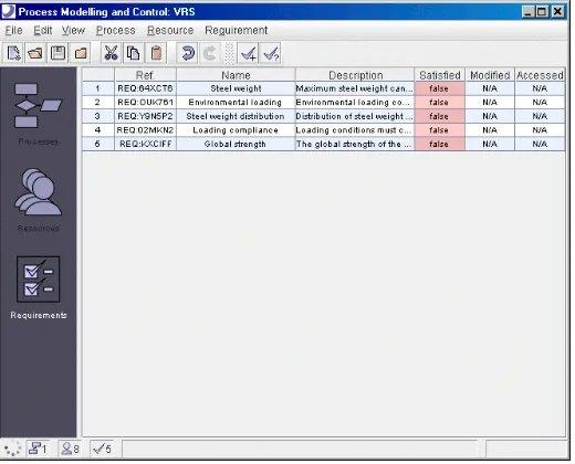
2.2 Requirement management
being generated through the management of the processes – Figure 3. The PCT can manage multiple requirements relating to either specific aspects of the product, general aspects across the product, or aspects across multiple products and processes. Requirements have two roles within the PCT: as a measure of the extent to which customer requirements have been satisfied; and to enable the control flow within a process to be directed on the basis of the outcome of the requirement. Through the user interface of the VIP, a designer may get a list of requirements and their states to determine how a project is progressing, and take appropriate action in order to satisfy any of these requirements. Alternatively, requirements may be associated with design activities within the PCT indicating that the activity, once enacted, is expected to contribute to the satisfaction of the requirement. When a designer completes an activity, the associated requirements are displayed within the user interface of the VIP, allowing the designer to indicate which ones have been satisfied. When an activity is completed, the PCT is notified, giving details of the activity, along with requirement and guidance information. For ROPAX design, the PCT may be managing the enactment of a process that is responsible for designing and evaluating the general arrangement which consists of a number of design and simulation activities, such as defining the compartments, corridors, stairwells and muster stations, and simulating the evacuation for example. Once the general arrangement activity has been completed, the PCT would allocate the evacuation simulation activity to a designer that can undertake it. The requirement might not be satisfied once the simulation is complete if the passengers failed to evacuate the vessel within a predetermine time limit for example, and the designer may subsequently choose to attach guidance stating that the general arrangement appeared to have a bottleneck around one of the stairwells, restricting the movement of the passengers. This guidance would be communicated to the PCT, which would direct process control back to the general arrangement activity, with automatically generated guidance stating that the requirement had failed, as well as the guidance from the designer stating the problem with the stairwell.
Figure 3. Process control tool – requirement representation.
2.3 Resource management
A resource management model was created within the PCT providing the following functionality to VIP designers:
• Manage the login administration processes onto the VIP.
• Configure activities and tools to be integrated within the VIP providing a mapping within the PCT of a designer’s capability.
• Allow activities to be allocated to users of the VIP.
• Communication with other designers.
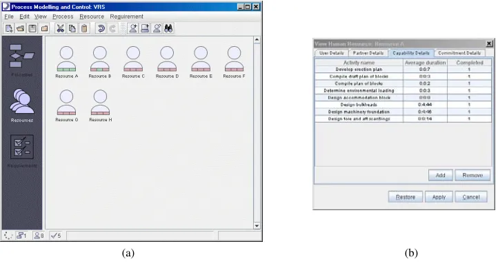
telephone number. Designers are defined within the PCT as having capability (the measured ability to perform an activity) – Figure 4(b), commitments (information related to which activities they are currently undertaking, and have undertaken in the past), and as being project managers. When a new project is created within the PCT, a project manager is associated with it. Information is also modelled with respect to the designer’s IP address which is obtained when the designer logs onto the VIP, and is used for all communication.
Through the VIP user interface, a designer can configure and integrate a design or simulation tool into the VIP, and in doing so, map the use of the tool to an activity within a process contained within the PCT – updating the designer’s capability automatically. The capability defined for each designer allows the VIP to keep track of the number of times that the designer has performed the activity in the past, as well as the associated durations. This information is used within both the local and global scheduling processes. When a designer configures a tool and registers a new capability, the PCT has a provision to allow the activity to be undertaken a number of times during a training period without the activity durations being considered in any subsequent planning. This training period is used within process scheduling to ensure that designers that have configured new capability (which could potentially take a number of undertakings before the designer becomes competent in performing the activity), are not always overlooked in preference for a designer that is more experienced and capable of performing the activity in less time.
[image:7.595.118.479.296.489.2](a) (b)
Figure 4. Process control tool – resource representation.
To aid accurate scheduling, the PCT also tracks the commitments that a designer has with respect to other activities that it is currently performing. When an activity is allocated to a designer, the PCT adds detail of the commitment to the information contained about the designer, which remains there until the designer has completed the activity.
3 RESOU RCE SCH EDU LI N G
The PCT manages the real-time enactment of processes through interaction with the VIP to allocate activities to designers. When a designer logs onto the VIP, the PCT authenticates the login and password controlling access to the platform. In order to provide efficient operational co-ordinate, the PCT is required to ensure that the most appropriate designers are scheduled for the activities. The PCT is capable of managing multiple processes each containing thousands of activities, as well as multiple designers logged onto the VIP each capable of performing various different subsets of the complete range of activities to various degrees of efficiency. The enactment of processes is also dynamic, with the PCT having the ability to co-ordinate the real-time enactment of all of the processes within a project simultaneously.
3.1 Local scheduling
The local scheduling approach determines the most appropriate designer to allocate an activity to according to the sequence of enactment. When an activity requires scheduling, the PCT queries the resource model and generates two lists of designers that are capable of performing the activity. The first list represents designers that have completed the training period for the activity (and are therefore assumed to be competent), and the second list represents the designers that are within their training period for that activity. The lists are ranked using information relating to how much time each designer expects to undertake the activity. Bias is always given towards designers that are within the training or “probationary” period for the activity for two reasons: it gives all designers the possibility of becoming more competent; and it ensures that the scheduling algorithm does not always allocate the most efficient designer to an activity, without at least giving newly capable designers the opportunity to improve their efficiency. If more than one designer is within the “in training” list, the designer is chosen at random, whereas the most efficient designer is always selected from the “trained” list. The PCT uses information relating to the designers’ capabilities and commitments to determine the expected duration for the activity. Using information of the durations taken for the designer to undertake the activity in the past, a moving average is firstly used to extrapolate an expected duration for the activity. Consideration is then given to the other activities that the designer is currently committed to undertaking (that have already been allocated) and their expected completion times. It is assumed that if a designer is committed to undertaking two activities, and is potentially being scheduled to undertake a third activity, that the designer will multi-task – spending an equal time on each activity, and not devote 100% of their effort on the third activity and ignore the first two activities. The PCT therefore assumes that three simultaneous one-hour activities would each take three hours to undertake. This assumption is necessary without direct negotiation with the designer and the need for the assumption is more apparent when performing scheduling across multiple processes. Finally, consideration is given when estimating the duration of the activity to be allocated on the anticipated completion times of other commitments, which may be completed before the end of the new activity, and will also have their durations affected by the new activity.
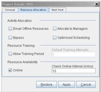
[image:8.595.212.383.548.704.2]The PCT may however fail to locate an appropriate designer for the following reasons: there are no designers currently online that can perform the activity; or there are no designers that can perform the activity. The control of the process is managed in these circumstances by the “Email Offline Resources”, “Allocate to Managers”, and “Bypass” control options – Figure 5. If an appropriate online designer could not be identified, and the “Email Offline Resources” option was checked, the PCT would generate a designer list for offline designers. The most appropriate offline designer would be selected, and the PCT would automatically send an email to the designer’s email address to inform that they have been scheduled for an activity, and request that the designer logs onto the VIP. The PCT would pause the activity and change its state to “pending”. When the scheduled designer, or any other designer that was capable of undertaking the activity, next logged onto the platform, the PCT would automatically re-start and allocate the activity.
Figure 5. Resource allocation configuration dialog.
would step over the activity and carry on with the following activities. If neither of the above options were checked, the PCT would pause the activity and change the state to pending. Providing these different options ensures that the PCT never reaches an activity that it has no rules to manage.
When an appropriate designer is scheduled, the PCT communicates with the designer to allocate the activity. The PCT determines the time-spent by the designer undertaking the activity taking into account the other commitments. There can be no guarantee however that the most appropriate designer for each individual activity, would also be the most appropriate designer when considered from a global perspective. This approach, cannot guarantee an optimum process lead-time, however it does provide additional functionality for managing activities that cannot be allocated, and for improving the designers’ efficiency through a training period. The approach may however be improved by determining the most appropriate designers for the future activities which would produce an optimum lead-time with respect to all of the activities that are currently being enacted (ignoring future activities) at any point in time.
3.2 Global scheduling
For global scheduling, the PCT considers the requirements of all of the activities within all of the active processes simultaneously with the aim of minimising the lead-time. When scheduling multiple processes, the PCT automatically generates a new schedule (for all active processes) whenever it attempts to start an activity that is not currently within its schedule. The schedule represents a mapping between each of the activities that require performing, the designers that will perform them, and the time period in which the activity would be performed.
A Genetic Algorithm (GA) is used to enable the optimisation of the schedule. The GA initially creates a population representing a number of plans, which consist of a randomly generated sequence of activities for each process. A schedule model is then used to select the most appropriate designer for each activity within this random sequence. The global scheduling approach does not consider whether the designer is currently online, since it may be scheduling a designer for an activity many days into the future, and would therefore not know whether the designer would be online at the time that the activity is due to be enacted. It also makes no consideration for bypassing activities – any activity that cannot be allocated to a capable designer, would be allocated to a project manager. The designers are selected using a similar basis as the approach used for local scheduling, with the exception that consideration needs to be given to the fact that the activities are not to be enacted immediately (as is assumed within local scheduling), they will be enacted some time within the future. Consideration therefore needs to be given for a designer’s future commitments when determining the expected activity duration.
The schedule provides an evaluation of the plans for each process and produces an estimate for the combined lead-time of all of the processes. The GA uses conventional techniques such as selection, crossover and mutation, over a number of generations in order to refine the plans and generate a schedule that has a near-optimum allocation of activities to designers with respect to process lead-time.
Global scheduling is a dynamic approach, reacting to the changing process demands, as well as simultaneously considering the most appropriate designers in order to minimise the lead-times of all of the active processes. Whenever an activity is completed, the scheduled designer is removed from the schedule, in order that if the activity were to be repeated due to iteration for example, the scheduling procedure would be repeated and therefore not use the same previously scheduled designer (which may no longer be optimal). A shortcoming of this approach is that the scheduling algorithm does not consider the availability of designers during working hours, which is compounded by the fact that the designers may be distributed across various time-zones, as well as the possible variation in the schedule and potential un-availability of a scheduled designer some time the future. These issues could however be addressed by continually assessing the deviation from the schedule and re-scheduling when the deviation exceeds pre-defined limits [1].
CON CLU SI ON
using the Process Control Tool (PCT). The PCT allows activities within process models to be allocated to designers of the platform irrespective of the physical or virtual location of the designer. Monitoring is provided to check the status of the activity, and allow the associated process to be co-ordinated in an efficient and effective manner. The efficiency is achieved through the choice of two different approaches for the selection of appropriate designers: local and global scheduling. The strengths and weakness of these two approaches within the context of the PCT are summarised as follows:
• Local scheduling considers the most appropriate designer to perform an activity on an activity-by-activity basis. When an activity is due to be started, the local scheduling approach selects a designer on the basis of time, and whether the designer is currently within a training or “probationary” period. This approach allows designers that may not have had previous experience in performing activities to be considered, rather than being neglected in favour of more experienced designers that may perform the activity in less time. If no probationary designers exist, the approach automatically adopts the designer that can perform the activity in the least time as calculated through extrapolation of previous task durations for that designer. Consideration is given to the affect on the duration of other activity commitments that the designer may have. Other than the individual commitments of the designer, the approach does not consider any of the other activities that require scheduling either in parallel or in the future. The approach therefore provides no consideration of the critical path, and cannot guarantee an optimal mapping of activities to designers.
• Global scheduling considers all of the activities that may require enactment, and attempts to optimise the mapping of designers to activities on the basis of minimising lead time. The
outcome of global scheduling would therefore result in consideration of the critical path of all of the processes that are currently active. The mapping between activities and designers is
generated for all future activities, whenever the schedule does not contain a mapping between a designer and an activity. This re-scheduling occurs whenever a new process is started, or when re-iteration occurs within a process since it cannot be assumed that the previous optimum mapping of designers to activities remains optimum. No consideration is given for probationary designers since the optimisation uses the single objective of time. Consequently, the designer that is expected to perform the activity within the least time will always be chosen in a like-for-like situation over an in-experienced designer. Despite considering concurrent future
commitments of designers, the global scheduling approach assumes that the designers will be available at the point when the activity would be allocated. Due to the dynamic nature of designers’ working lives, this assumption may quickly result with a schedule that is no longer optimum.
Since the scheduling process is performed automatically by the PCT, additional measures are available for reacting to situations where no designers may be identified that could be allocated the activity including: emailing off-line designers and requesting that they log onto the VIP; allocating the activity to a manager within the project; or bypassing the activity completely.
The CAD Centre is currently involved within a number of projects that aim to build upon various aspects of the VIP and add functionality to further develop resource scheduling and other distributed collaborative aspects such as decision support for example. These projects are: Network Enabled Capability Through Innovative Systems Engineering (NECTISE – funded by EPSRC and BAE Systems), The Virtual Tank Utility in Europe (VIRTUE – funded by EU), and Design, Operation and Regulation for Safety (SAFEDOR – funded by EU). Each project is a collaborative endeavour, with the number of partners varying from 11, to over 70. VIRTUE will for example manage multiple projects consisting of either the same, similar or different processes, with multiple users working across these projects adding another layer of complexity to the co-ordination within the PCT.
and Cost (PERC) analysis tools will be wrapped in a similar approach to that adopted within the VIP, as well as VIRTUE, and form the basis for distributed collaborative risk-based design.
ACK N OWLEDGEM EN T S
This research is funded by the European Commission (grant No. G3RD-CT-2001-00506), which is part of the Fifth Framework Programme for Research, Technological Development and Demonstration. The NECTISE project was jointly funded by BAE Systems and the Engineering and Physical Science Research Council under grant number EP/D505461/1. Both the SAFEDOR and VIRTUE projects were partially funded by the European Commission (contract numbers FP6-516278 and FP6-516201 respectively), within the Sixth Framework Programme. The opinions expressed are those of the authors and should not be construed to represent the views of either the VRShips, NECTISE, SAFEDOR or VIRTUE partnerships.
REFERENCES
1. Coates, G., et al., An integrated agent-oriented approach to real-time operational design co-ordination. Journal of Artificial Intelligence for Engineering, Design, Analysis and Manufacturing, 2003. 17: p. 287-313.
2. Coates, G., et al. Real-time co-ordinated resource management in a computational environment. in 14th International Conference on Engineering Design. 2003. Stockholm, Sweden: The Design Society.
3. Coates, G., et al. A methodology for prospective operational design co-ordination. in 14th International Conference on Engineering Design. 2003. Stockholm, Sweden: The Design Society.
4. Hogg, T. and B.A. Huberman, Controlling chaos in distributed systems. IEEE Transactions on Systems, Man, and Cybernetics, 1991. 21(6): p. 1325-1332.
5. Andreasen, M.M., et al., The design co-ordination framework: key elements for effective product development, in International Engineering Design Debate: The Design Productivity Debate. 1996: Glasgow, UK.
6. Duffy, A.H.B. Ensuring competitive advantage with design co-ordination. in 2nd International Conference on Design to Manufacture in Modern Industry. 1995. Bled, Slovenia.
Contact: R.I. Whitfield University of Strathclyde
Department of Design, Manufacture and Engineering Management 75 Montrose Street
Glasgow, G1 1XJ UK