Distributed design coordination
Robert Ian Whitfield, Alex H. B. Duffy, Graham Coates, William Hills
Abstract This paper describes a computer-based system called the design management system (DMS) that was developed to manage and coordinate distributed engi-neering design activity. Issues relating to the control of distributed design coordination are discussed from the context of engineering design. Key features of the DMS as well as proposals for future developments are described. Distributed design activity is coordinated and managed using the DMS within an industrial case study. The DMS demonstrated significant improvements in timeliness when compared with manual process-enactment tech-niques (64% reduction in process time compared with previous methods). Further potential system improve-ments are identified relating to operational coordination.
Keywords Distributed design, Strategic coordina-tion, Concurrent engineering
1
Introduction
Throughout the conceptual, detail and embodiment stages of the product development process, it is increasingly common that analysis tools are involved in the evaluation of a large number of potential design solutions as the iterative process refines from a set of customer require-ments to a design artefact. Designers use such analysis tools to assist with large-scale evaluations and in the production of solutions that satisfy the requirements.
Consequently, there exists a need to coordinate the design activity to enable these stages of design to be performed in a timely and appropriate manner. The design activity within large made-to-order (MTO) development processes is becoming distributed both organisationally and globally, and conventional management and coordination of the product development process is becoming increasingly difficult since there are many factors that need to be simultaneously considered in order to effectively manage the complexities of scale and to produce an artefact that satisfies the customer’s requirements.
This paper describes a generic system that allows the management and coordination of design analysis tools. A computer-aided design tool, the design management sys-tem (DMS), has been developed to assist the designer in performing computational analysis in a distributed com-puting environment. The focus of the DMS is the man-agement of the design processes, activities, information and goals within the product development process.
The advantages and disadvantages of different strategies for the coordination of the distributed design process and the novel approach developed within the DMS are discussed. An industrial case study is described that represents the design activity required to determine various performance characteristics for the bladepath design for a steam turbine. The conventional method of management for this process is discussed and compared to that using the DMS.
2
Centralised and distributed coordination control
The arguments supporting the management of coordina-tion within either centralised or distributed frameworks are many and varied (Decker and Lesser 1992; Jennings 1996; Lesser 1998). Those in favour of distributed control frameworks usually refer to bottlenecks and catastrophic failure as being shortcomings of centralised frameworks, whilst those in favour of centralised control frameworks refer to significant increases in network and processing requirements and overall complexity as being shortcom-ings of distributed frameworks. Rarely, however, has anyone considered the management of distributed coor-dination from an engineering design perspective (An-dreasen et al. 1996; Coates et al. 1999, 2000a; Whitfield et al. 2000), and more importantly, from the requirements of the engineering designer.
Despite not focussing specifically upon engineering design, Malone et al. (1997) proposed two design princi-ples for the design of agent-based systems that have had considerable impact upon the development of the DMS:
243
Received: 15 October 2001 / Revised: 28 April 2002
Accepted: 7 August 2002 / Published online: 10 September 2002
Springer-Verlag 2002
R.I. Whitfield (&), A.H.B. Duffy CAD Centre, University of Strathclyde, James Weir Building, Montrose Street, Glasgow, G1 1XJ, UK
E-mail: [email protected] Tel.: +44-141-5483020 Fax: +44-141-5520557 G. Coates, W. Hills Engineering Design Centre, University of Newcastle, Armstrong Building,
Newcastle upon Tyne, NE1 7RU, UK
Don’t build computational agents that try to solve complex problems all by themselves. Instead, build systems where the boundary between what the agents do and what the humans do is a flexible one. We call this the principle ofsemiformal systems...
Don’t build agents that try to figure out for themselves things that humans could easily tell them. Instead, try to build systems that make it as easy as possible for hu-mans to see and modify the same information and reasoning processes their agents are using. We call this the principle ofradical tailorability...
A number of issues were identified following discus-sions with engineering designers and management within the made-to-order sector that justified the use of these design principles:
• Despite most made-to-order sectors having well-estab-lished processes, the management of the process from a designer’s perspective may well be ad-hoc due to both the evolution of the process, and the evolution of the designer’s understanding of the process. Different designers may be given the same design problem and process, but may manage the process differently (from a slightly different understanding of the problem) to come to a similar solution that satisfies the requirements. It is the designer’s individuality ortailorabilitythat needs to be considered such that a designer may coordinate their activity using the knowledge and experience with which they are familiar.
• The coordination mechanisms contained within the process need to be easily manipulated by the designer such that the effect of changes to the product’s re-quirements may be considered within the process. Distribution of control knowledge throughout an automated system increases the complexity of the system by passing the control from the humans (who may easily figure it out), to the agents (who may not). A partially centralisedapproach to the management of control was preferred within the DMS since it allowed organisationally or geographically distributed designers to locally manage the control mechanisms of processes with which they were familiar, rather than be governed by the rules within a distributed knowledgebase. • Given a product’s design requirements, the design
process typically goes through a number of iterations before the requirements are satisfied (Andreasen and
Hein 1987; Hubka 1982). Within the MTO sector this may involve the enactment of thousands of tasks of varying degrees of complexity, many of which may be automated to remove the burden from the designer. The DMS aims to automate the processwherever appropriate such that the designer can concentrate more on the outcome of the task rather than on performing the task. • The DMS provides a generic model of a design task
irrespective of whether the task is performed by a computational agent or by a human agent. It thereby provides a flexible boundary between what a designer can do and what an agent can do.
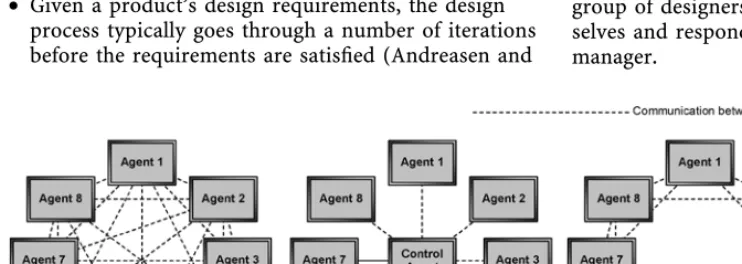
Jennings (1996) discussed the coordination and man-agement of the control mechanisms within distributed artificial intelligence from three different perspectives. The first scenario required an unlimited amount of processing power to enable each agent to be aware of the goals, actions and interactions of all of the other agents within the community (Fig. 1a). This scenario was not considered practical since processing power is rarely unlimited, and the requirement for each agent to be constantly aware of the other agents within the community is unnecessary and complicated. Furthermore, within the context of engi-neering design, the computational focus is directed away from doing the design such that every agent becomes a manager responsible for their own, and the coordination of each other’s activities.
[image:2.658.48.419.608.740.2]The next scenario was to provide a single management agent with all of the control mechanisms required to co-ordinate the community of agents (Fig. 1b). This proposal has advantages over the previous scenario, since it dem-onstrates a significant reduction in the overall complexity of the system, by removing the management of control from the community of agents, and shifting the focus back towards performing design activity. Additionally, if all of the control mechanisms were managed and coordinated by a single agent then the inspection of these mechanisms would be significantly easier than if the control was distributed across the community. This scenario has the drawback, however, that the management agent would potentially become a bottleneck as well as risking the possibility of complete failure of the community because of the failure of this agent. It is also rare in practice that a group of designers have no interaction amongst them-selves and respond only to the direction of a single manager.
Fig. 1. Distributed
coordina-tion scenarios
Jennings’ final scenario involved the distribution of the control mechanisms to the agent community to the extent that each agent had only a partial perspective of the overall coordination problem and therefore did not restrict the resources available to undertake their activities (Fig. 1c). Each agent would effectively become a ‘local manager’. This scenario was demonstrated by Decker and Lesser (Decker and Lesser 1992; Lesser 1998) within an approach called generalised partial global planning, where a com-munity of agents communicated to form partially global plans for the other agents within their community. The approach did, however, restrict the computational re-sources available to undertake the agents’ activities, being outperformed by a centralised system 57% of the time whilst producing 85% of the quality.
Duffy et al. (1993) discussed design coordination within the context of concurrent engineering and identified a number of inherently complicated issues that need to be addressed in order to improve product development performance. The difficulties in addressing these issues ‘highlight both the limitations of humans to cope with complexity, and the considerable strengths of humans to reason, judge, learn and interact’. The authors go further to suggest that ‘systems can be structured to provide active support for human limitations without infringing on the fundamental strengths of human activities’. These two statements support the principles of Malone, i.e. combine the strengths of both the human and computer.
On the basis of these issues, distributed design man-agement and coordination within the DMS was defined as a two-stage approach. The first stage required providing centralised control mechanisms that would enable tasks to be represented, managed and coordinated as a series of distributed and inter-related activities. The second stage enables these centralised control mechanisms to be ap-propriately distributed by viewing the tasks at a higher level of abstraction.
Coates (2001) discovered some ambiguity within a survey of the usage of the terms ‘task’ and ‘activity’, and provided the following definition:
Goals are accomplished or achieved through undertaking tasks that are completed by performing or carrying out activities.
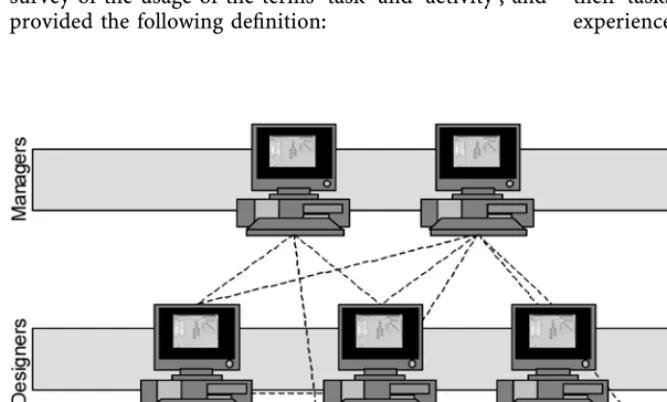
Within the context of the DMS, these activities are carried out by a number of organisationally or geograph-ically distributed servers, which are coordinated through a client that contains a centralised description of the rela-tionships between the activities as well as a list of the goals to be achieved through the undertaking of the task (Fig. 2). The servers contain all of the domain-specific information and knowledge in order to manage and coordinate the tasks for which they are responsible. The relationships between the activities, the activities themselves, the asso-ciated information and the goals are represented within a design process using the DMS client software. The de-signer is responsible for selecting the servers that are to be used within a design process. The tasks that the server is capable of undertaking are communicated to the client software upon connection to a service. The designer using the client software manages the overall design process. A number of servers may be used to carry out the same activities, in a similar way that a number of designers within a company may perform similar activities. Also, a number of designers using the DMS client may commu-nicate with the servers to undertake similar tasks using the same process. A number of different processes may be created including activities from servers specialising in other disciplines.
The generic and abstract nature of Coates’ definition enables the processes (or tasks) containing centralised control mechanisms within the clients to be regarded as activities carried out by servers within a process at a higher level of abstraction. The DMS enables higher-level centralised control to manage lower-higher-level
[image:3.658.47.381.537.738.2]distributed control. The DMS also at each level provides the appropriate management, provides a flexible interface between what the designers can do and what the servers can do and enables designers to tailor their tasks according to their own knowledge and experiences.
Fig. 2. Partially centralised configuration
3
DMS architecture
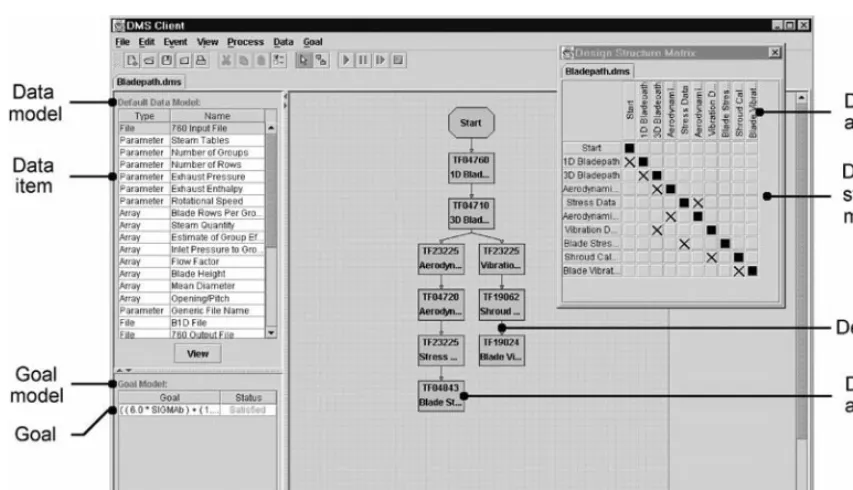
The DMS is a domain-independent design coordination and management system (Fig. 3). The focus of the DMS is to provide a framework that allows engineers to efficiently and effectively coordinate distributed design activity. The DMS does not attempt to remove the decision-making process from the designer; instead it manages the com-plexities of scale such as engineering design data, design resources (servers), design processes and design goals. These complexities of scale are discussed in further detail. The DMS does not contain any problem-specific knowl-edge other than the process knowlknowl-edge. Hence it is ap-plicable to the management and coordination of different stages of a product’s development as well as different life phases. The problem-specific knowledge is, however, encapsulated with the problem-solving servers that carry out the specific analysis activities.
3.1
Data management
One requirement of distributed design coordination is the effective communication and management of engineering data to ensure that designers and engineers are operating with a consistent and current product data model. A number of different data representations are currently available such as STEP (Peng and Trappey 1998; http:// pdesinc.aticorp.org/) and XML (http://www.w3.org/XML/) and, recently, mappings between STEP and XML (Kimber 1999; http://www.stepml.org). However, an alterative rep-resentation was developed to enable engineering data to be easily modelled, communicated and modified by design-ers. It was also believed that the implementation of a STEP-based data representation would focus too much attention upon satisfying the specifications of such a representation as well as significantly increase the com-plexity of the system, making the system more difficult to
extend for future applications and taking the focus away from coordination issues.
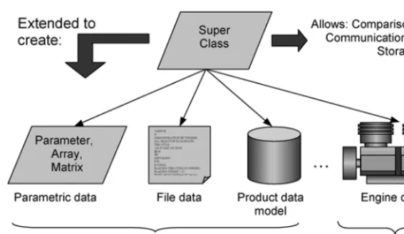
An abstract data representation was developed and extended to model information types such as parameters, arrays, matrices and files using common object-oriented (OO) design techniques, for example, inheritance and polymorphism (Fig. 4). The abstract data type provided an interface for the definition of new data types as well as a powerful mechanism to facilitate the management of engineering data. Each data type may be represented graphically within the DMS according to its own specific requirements, allowing for inspection and modification by the designer. The OO design approach also enables the production of more complex data types, for example, parametric descriptions of engineering artefacts such as journal bearings, which are represented within an interface that displays the information three-dimensionally. In addition, it is possible to extend the abstract data type to represent STEP-based data for future implementation. Rules may also be included within the data types to constrain values as well as provide interaction within more complex data types. Within the file data type included within the DMS software, for example, data is typically read from a disk as a result of performing an activity and is communicated over the network to the designer. A parser may be included within the file data type to transform the data into a specific parametric format using any of the available data types.
This OO data representation also enables the
[image:4.658.48.475.48.293.2]development of data models capable of managing all of the information for a particular activity or process. When an activity within the process is enacted, the data that is produced as a result of this activity is placed within the data model, replacing the previous version of the data and ensuring consistency of the engineering data within the process. Notification is given to the user in the event of an older piece of data replacing a more recent version.
Fig. 3. DMS client interface
The abstract data type has mechanisms to enable the communication of either individual pieces of data or entire data models across a network. These mechanisms enable large amounts of information to be compactly represented and securely communicated across a network without any requirement for encoding or decoding at either end. It also enables data models to be stored persistently (using object serialisation) to a hard disk for future use. Data and data models within the DMS may be transferred across a network between different operating systems and versions of the Java virtual machine without any special considerations.
Although not currently implemented within the DMS, the data model structure is intended for future versions to enable:
• Design reuse: a history of previously explored design data models for a particular process, stored persistently within an archive, to provide the designer with a basis for the consideration of a new design variant. An in-vestigation would reveal aspects of previous design models that may be utilised within the current concept, eliminating rework and reducing the overall process evaluation time. This approach would enable a ‘pull’ rather than ‘push’ approach to concept generation. That is, rather than explore the design space to determine a solution that satisfies the design requirements, explore the solution space to locate archived solutions that ei-ther satisfy or come close to satisfying the design re-quirements and use these solutions as the basis for the new concept.
• Sensitivity analysis: the DMS currently determines the sequence of activities to perform a task based upon the dependencies within a design structure matrix (Whit-field et al. 2001). Initially all of these (informational) dependencies are considered to be strong (with a large weighting), since little is known about the relationships when the process is designed. However, through analy-sis of the previous design data models, it is possible to determine the sensitivity of each of the dependencies (Eppinger et al. 1994). Dependencies are represented as weak when data is known to lie within predictable limits, and are represented as strong when there is an unpredictable nature to the data. This improved understanding of the weightings of the dependencies within the DSM, along with a design history for the process, would enable activities to be decoupled using
previous predictable data to increase concurrency and would provide better-quality information for feedback loops to reduce iteration.
• Tracking of Pareto optimality: the goals and require-ments associated with a particular task may be used to determine the suitability of the previous design models. Given this information, it is possible to determine which of the models best satisfies the goals and requirements and also produce a Pareto-optimal design front to identify important regions within the design space (Petrie et al. 1995). The concept of Pareto optimality may also be utilised along with the process design his-tory to provide feedback with respect to the effects of changes on the quality of the solution and to provide the designer with an increased understanding of the trade-offs between the goals and requirements.
3.2
Server management
The DMS uses Java remote method invocation (RMI) to enable communication between the client and the server. RMI’s basic connectivity between the machines on a network is established using the transmission control protocol (TCP/IP). DMS servers may be started on any computer connected to the Internet, provided that the computer has a Java runtime environment (JRE) devel-oped for it. The servers are therefore independent of the platform upon which they are running, as well as the version of the JRE that they are using. The Internet pro-tocol (IP) address or alias is used to specify the host on which the server is running. However, the server is not specific to a particular IP address. A connection is made to the server from the client via a naming service to provide the client with a reference to a remote object that enables communication with the server. This process is under-taken transparently from within the DMS client with the provision of the requirement of the server’s name and IP address and enables clients to connect to organisationally and geographically distributed servers running on any combination of platforms and versions of the JRE.
[image:5.658.47.331.48.212.2]It is possible to have more than one DMS client connected to a server, as well as having more than one instance of a particular server connected to the client. A number of clients sharing the server has implications regarding the effective utilisation of both the server as a
Fig. 4. Object-oriented data model
resource and the computational resource that the server is using.
After a DMS client has connected to a server, the details of the activities that the server may undertake are com-municated to the client. These activities may then be in-cluded within a process such as that shown in Fig. 3. The activity also contains details regarding the information that is required for the activity to be undertaken, as well as the information that will be produced from undertaking the activity. When an activity is ready to be enacted, the details of the activity as well as the data that is required to undertake the activity are communicated to a suitable server.
The server is structured to accept and carry out one activity at a time primarily to attempt to avoid complexity; however, this limitation is the focus of current investiga-tion. The management of a single activity at any one time provides a potential bottleneck in the situation where more than one client is connected to a server that receives requests for more than one activity to be carried out. In this situation the activities will be put in a queue and carried out when the previous activity has been completed. The DMS manages this shortcoming by allowing any client to connect to more than one instance of the same server. The DMS attempts to locate an idle server (to which the designer has previously connected) that is capable of performing a particular activity, otherwise queuing the activity with a suitable busy server.
A primary focus for the future development of the server-side implementation is the consideration of both the capabilities of the server in performing a particular activity with respect to activity duration and efficiency, and the ability to undertake multiple activities simulta-neously. The DMS would then negotiate with the servers in a similar way as that developed within the contract-net protocol (Smith 1980) to determine the server that can most efficiently carry out the activity, whilst simulta-neously considering the requirements and efficiency of the process. For example, if an activity is not on the critical path then do not consider giving it to an efficient server that may be on the critical path. The overall duration, however, for a single server to perform a number of events sequentially or simultaneously is expected to be the same, providing that the server has a single processor. These and other operational design coordination issues are further discussed by Coates et al. (2000b, 2000c) and Coates (2001).
When a server has undertaken an activity successfully, the result of the activity as well as any new design data generated is communicated back to the client. The client immediately places the data into the data model for the process to ensure consistency.
3.3
Process management
The DMS may be used to construct, manage and simul-taneously enact a number of design processes either within similar or different domains. Relationships between pro-cesses may be developed such that design data can be shared, for example, between processes representing mechanical and electrical domains for the same design
artefact. It is also possible to have more than one instance of the same design process running within a single instance of the DMS client to enable the simultaneous consideration of different design problems, goals or requirements.
When the process is enacted, the information that is required to carry out the activity and the details of the activity are communicated to a suitable server. The server then manages the enactment of the activity and commu-nicates the results of the activity and any design data back to the client. The data is then stored within the associated data model for use by other activities, inspection by the designer or inclusion within design goals. Notification is given to the designer in the event of a server failure either during the enactment of the process within the client, or whilst it is performing an activity. The activity is rerouted if there is another server available that can perform the activity, or alternatively, the designer can choose to re-connect to the server and attempt to perform the activity again. In either case, however, the failure of the server is managed to minimise the impact to the process.
The process may be paused and continued or stopped at any point during the enactment. If the process is paused and saved to a disk, the process may be loaded at a later stage and continued from the point at which it was paused. As well as saving the activities, data and goals within the process, the state of the process is also saved in order to reduce rework. When the process has been completed, outstanding design goals are evaluated and notification is given to the designer regarding their status.
3.4
Goal management
Goals have been included within the DMS to enable de-signers to check the suitability of the design model with respect to satisfying the design requirements. These have currently been limited to constraint-based goals where the objective is to satisfy some requirement. The constraint goals are generated by constructing an expression using parametric information such as the matrix, array and parameter data types contained within the design data model. Expressions may be constructed using all of the common arithmetic and logical operators. An example of the expression builder used to construct a design goal is shown in Fig. 5.
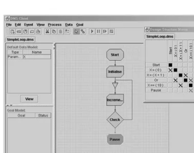
The expression builder may also be used to construct criteria that may be added within the process, such that the criteria may be evaluated as a part of the process ex-ecution. This mechanism enables designers to check that specific parts of the process satisfy particular requirements and to take appropriate action depending upon the outcome. These runtime criteria goals have two outcomes such as that shown within the ‘Check’ event within Fig. 6. In this simple example the DMS has a single parameter ‘X’ that is initialised, incremented, then checked to see if it has a particular value. If not, the process iterates back to the increment and repeats. The process is paused when the check returns true.
Despite being a simple example, Fig. 6 demonstrates how constraint-based goals may be included within a process so a designer may check that certain requirements
have been satisfied during process enactment and take appropriate action on the outcome.
Given the future inclusion of the tracking of Pareto-optimality it will also be able to include target-based goals where the objective may be defined as, for example, maximise efficiency, minimise cost, etc.
4
Case study
The process presented within Fig. 3 represents the activi-ties that are undertaken by Siemens Power Generation Limited in order to determine a number of performance characteristics of the bladepath for a steam turbine. The process is typical of the types of design activity that
Siemens Power Generation Limited use during the detail design stage of turbine design.
The turbine bladepath is represented by a series of stepped sections along the length of the turbine shaft. A specific number of blades are attached to each section of the shaft with the geometry of the blades varying along the shaft. Between each set of moving blades is a blade row that is fixed to the outer casing of the turbine to redirect the flow of steam as it passes through the turbine.
[image:7.658.46.332.49.233.2]The case study was conducted within a laboratory where access to computational resources was unrestricted. The results generated and issues identified with respect to the utilisation of resources are, however, similar to those within industrial practice.
Fig. 5. Expression builder
Fig. 6. Simple iterative loop
[image:7.658.46.425.264.562.2]4.1
Previous enactment
Experienced design engineers previously managed the bladepath design process, activities, goals and design data manually. It was common for a number of designers to undertake the same activities and hence use the same design tools simultaneously on different design problems. Iteration within the process was required in order to produce a design that satisfied a demanding set of re-quirements. Each design tool was run in turn and the output checked to ensure that the requirements were satisfied. The output was then transferred to a suitable location for the following design tool and the process repeated. If the requirements were not satisfied, the input information for either the tool or the process was modified and a further iteration made. The design tools produce large amounts of design data requiring inspection that took significant care to ensure against human error. The manual enactment of a single iteration of the process without inspection of any of the output data typically took approximately 8 min, depending upon the platform upon which the design tools were run. This was considerable longer than the critical path for the process, which was approximately 3 min. The entire design process for the bladepath may take significantly longer than this because of the number of iterations required to produce a satis-factory solution. The decisions made during this iteration process are complex due to the highly nonlinear nature of the problem and are based upon the designer’s experience using the design software. The DMS is therefore appro-priate for this type of design problem – to provide the tailorability to enable different designers to work on the same process, using their own knowledge and experience to solve the design problem and satisfy the design requirements.
4.2
DMS enactment
The DMS client software is generic and initially contains no domain-specific knowledge of the process. A design problem starts with the designer connecting to the servers that are to be included within the process. The DMS client software has the functionality to enable the designer to connect to any number of servers that are required within the process. Java RMI automatically creates the TCP/IP connection in order to enable com-munication between the client and server. The servers communicate details of the tasks and their associated data to the client software such that the designer may include the tasks within the process. It is assumed that the designer has an understanding of the process, where the tasks fit within it, and what the intertask dependen-cies are. As tasks are included within the process, the associated data is included within the process’s data model. This data may then be used to create any number of constraint-based goals that are evaluated upon com-pletion. The tasks are connected together to define the dependencies as well as the sequence of enactment. Once connected, the process may be enacted any number of times either manually or automatically until the goals
have been satisfied. The process may then be saved to the disk and restored for later use.
It was decided to demonstrate the application of the DMS to this design problem using two designers, A and B, connected to the design servers through two DMS clients in order to highlight a number of distributed design and resource-sharing issues. The case study represented one complete iteration of the design process for each designer. The case study may, however, be easily scaled up to represent a greater number of designers connected to a greater number of servers via the DMS clients.
A design server was created for each of the seven design tools. These servers were started on different machines of similar processing capability. Designers A and B then started the DMS client on the machine that they were using. In both cases, the clients were running on machines that had a server running on them; however, the clients require little processing capability during process enact-ment and were considered to have little effect on the outcome. The same bladepath design process was then loaded into each of the clients (Fig. 3). This process in-cluded a single goal that checked a blade stress constraint; however, other goals could be easily included to check other constraints. The data used by the designers was local to their client software and was managed by the servers accordingly in order to avoid conflicts.
In this initial situation, both designers were connected to the same servers. It was decided that the most difficult coordination problem to manage is when both designers started process enactment at approximately the same time – designer A followed by designer B 10 s later. This situ-ation results in designer A accessing the TF04760 server first, with designer B having to wait for the server to be-come available before carrying out the first activity. It was expected that there would therefore be a delay approxi-mately equal to the duration of the first activity between designer A and B completing one iteration of the process. The first task within the process has the longest duration, hence it was expected that designer B would not catch up to designer A.
It can also be seen from Fig. 3 that the process splits to form two threads of parallel design activity, which the DMS coordinates concurrently. The TF23225 server is, however, responsible for design activity at the start of both of these threads. Therefore one of the threads will be blocked until the TF23225 server has completed the first activity. No priority is currently given to which thread of activity is first to get access to the server.
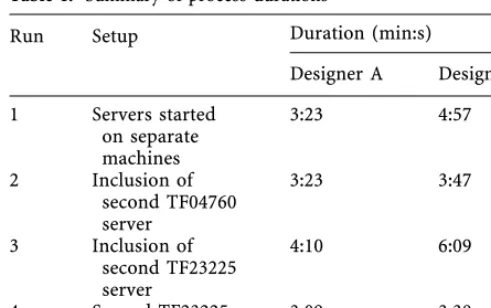
The process-enactment duration for designer A took 3 min, 26 s, including the evaluation of a single goal (to check the blade stress constraint) and represents a sig-nificant improvement in timeliness compared to that of the manual enactment of the process. This was achieved through the automatic management of data as well as the coordination and enactment of concurrent activities. The DMS also provided all of the design data to the designer in a convenient form to enable further inspection. The pro-cess-enactment duration for designer B was slightly longer at 4 min, 57 s. The difference between process times corresponds quite closely to the duration in which de-signer B was waiting for the TF04760 server to become
available. A summary of process durations can be seen in Table 1.
Another instance of the TF04760 server was started since this server was clearly a bottleneck within the case study. The second TF04760 server was started on a ma-chine that had a server towards the end of the process to attempt to avoid simultaneous use of the processor by each of the servers. The process was repeated, and on this oc-casion designer B located the new idle server, removing the initial bottleneck. The following activity on the TF04710 server proved to be the next bottleneck, with both designers requiring the server to perform activities at a similar point in time. This activity was, however, of a rel-atively short duration and hence was not considered to be sufficiently important to justify starting another instance of the TF04710 server. Designer A completed the process in 3 min, 32 s, whilst designer B completed the process in 3 min, 47 s. The inclusion of another instance of the TF04760 server significantly reduced the process duration for designer B, whilst having no impact on designer A. It is apparent from Fig. 3, however, that the TF23225 server could be a bottleneck, and indeed this was the case with four requests for activities from the designers.
Another TF23225 server was started on a machine that again already had a server running on it; however, the processes took 4 min, 10 s and 6 min, 9 s for designers A and B. The most probable explanation for this was that the server that was already running on the machine was car-rying out tasks at similar times as the new TF23225 server, and hence was not using the full computational resource. This result was initially surprising, until it became ap-parent during process enactment that the resources could potentially be used more effectively than demonstrated during this test. The new TF23225 server was then moved to a different machine and the process repeated. On this occasion, the process durations were reduced to 3 min, 9 s and 3 min, 38 s for designers A and B, respectively. The differences between the process times are most likely due to the bottleneck of the TF04710 server as discussed pre-viously.
This case study has demonstrated that the DMS is ca-pable of managing multiple processes efficiently and ef-fectively. In one instance the process duration was only fractionally longer than the critical path. Resource
selec-tion is clearly not a trivial problem, impacting on the process duration and requiring a good understanding of the interactions within the process. The inclusion of an operational coordination methodology such as that de-veloped by Coates (2001) would enable the selection of effectively managed resources such that the design process may be undertaken in a near-optimum manner.
5
Conclusions
A new system for the coordination of distributed design activities is presented. The system enables design activity to be coordinated in a timely and appropriate manner. The focus of the system is to provide mechanisms that facilitate the decision-making process of the designer and effectively manage the design process. The system also demonstrates the necessity of a flexible coordination framework as the basis for supporting concurrent engineering, design reuse and design and process optimisation. From a concurrent engineering perspective the focus is more towards en-abling concurrency, rather than maximising concurrency by decoupling activities, thus allowing the design process to progress naturally.
The approach was evaluated using an industrial case study that had a well-established design process. The ac-tivities within the process as well as the management of the information resulting from the activities were previously performed manually using a number of different com-puter-based design tools. Upon completion of the process, the results from the design activities would be used within calculations to check that the design concept satisfied the constraints. Alterations would subsequently be made to the parameters that were thought to be preventing the concept from satisfying the constraints, and the process would be repeated until the design concept fulfilled these requirements. The time taken to evaluate a design concept through the manual enactment of a single iteration of the process was approximately 8 min.
The design tools were each managed by a design server within the DMS system. The design process was con-structed using information obtained from these servers. The case study investigated the interactions between two designers using the same process on separate clients with the servers. Each designer was initially connected to the same servers. The designers enacted the process simulta-neously in order to highlight issues regarding bottlenecks and resource utilisation. In each case, however, significant improvements were made with respect to timeliness compared with the manual enactment.
A number of other server configurations were consid-ered, finally demonstrating that process execution times similar to the time for the critical path could be obtained for both designers, corresponding to a 64% reduction in process execution time. The most significant reason for this reduction was because the DMS was able to coordinate and enact concurrent activities. This reduction is, how-ever, specific to the structure (activities and dependencies) of the process under investigation. Despite delivering significant reductions in process durations, the case study demonstrated that there is a definite requirement for the
Table 1. Summary of process durations
Duration (min:s)
Run Setup
Designer A Designer B
1 Servers started
on separate machines
3:23 4:57
2 Inclusion of
second TF04760 server
3:23 3:47
3 Inclusion of
second TF23225 server
4:10 6:09
4 Second TF23225
server moved
3:09 3:38
integration of a more structured approach for the utilisa-tion of resources such as that presented by Coates (2001). The DMS was also responsible for managing the con-straints such that the stresses within the blades and the vibration characteristics met certain predetermined requirements. This was achieved by altering various geometrical characteristics of the blades using specific guidelines.
References
Andreasen MM, Hein L (1987) Integrated product development. IFS/ Springer, London
Andreasen MM, Duffy AHB, MacCallum KJ, Bowen J, Storm T (1996) The design coordination framework: key elements for effective product development. In: Proc First International Engineering Design Debate (EDD’96), Glasgow, 23–24 September, pp 151–174 Coates G, Duffy AHB, Whitfield RI, Hills W (1999) A methodology for design coordination in a distributed computing environment. In: Proc 12th International Conference on Engineering Design (ICED’99), Munich, 24–26 August
Coates G, Whitfield RI, Duffy AHB, Hills W (2000a) Coordination approaches and systems. II. An operational perspective. Res Eng Des 12:73–89
Coates G, Duffy AHB, Hills W, Whitfield RI (2000b) A generic coor-dination approach applied to a manufacturing environment. J Mater Proc Technol 107:404–411
Coates G, Ritchey I, Duffy AHB, Hills W (2000c) Integrated engi-neering environment for large complex products. Int J Concurrent Eng Res Appl 8:171–182
Coates G (2001) An approach to operational design coordination. PhD thesis, University of Newcastle upon Tyne, UK
Decker K, Lesser V (1992) Generalising the partial global planning algorithm. Int J Intell Co-operative Inform Syst 1:319–346
Duffy AHB, Andreasen MM, MacCallum KJ, Reijers LN (1993) Design coordination for concurrent engineering. J Eng Des 4:251–265 Eppinger SD, Whitney DE, Smith RP, Gebala DA (1994) A
model-based method for organizing tasks in product development. Res Eng Des 6:1–13
Hubka V (1982) Principles of engineering design. Butterworth Scientific, London
Jennings NR (1996) Coordination techniques for distributed artificial intelligence. In: O’Hare GMP, Jennings NR (eds) Foundations of distributed artificial intelligence. Wiley, pp 187–210
Kimber WE (1999) XML representation methods for EXPRESS-driven data. National Institute of Standards and Technology, GCR 99-781
Lesser V (1998) Reflections on the nature of multi-agent coordination and its implications for an agent architecture. Autonomous Agents Multi-Agent Syst 1:89–111
Malone TW, Lai K, Grant KR (1997) Agents for information sharing and coordination: a history and some reflections. In: Bradshaw JM (ed) Software agents. AAAI, Menlo Park, Calif, pp 109–143 Peng TK, Trappey AJC (1998) A step toward STEP-compatible
engi-neering data management: the data models of product structure and engineering changes. Robotics Comput-Integ Manuf 14:89–109
Petrie C, Webster TA, Cutkosky MR (1995) Using Pareto optimality to coordinate distributed agents. Art Intell Eng Des Anal Manuf 9:261–281
Smith RG (1980) The contract net protocol: high-level communication and control in a distributed problem solver. IEEE Trans Comput C-29:1104–1113
Whitfield RI, Coates G, Duffy AHB, Hills B (2000) Coordination approaches and systems. I. A strategic perspective. Res Eng Des 12:48–60
Whitfield RI, Coates G, Duffy AHB, Hills W (2001) A system for coordinating concurrent engineering. In: Proc 13th International Conference on Engineering Design (ICED’01), Glasgow, Scotland, 21–23 August, pp 393–400