Integrated Engineering Environments for Large
Complex Products
G. Coates1, I. Ritchey1,A.H.B. Duffy2, W. Hills1, R.I. Whitfield1 1
Engineering Design Centre, University of Newcastle, Newcastle upon Tyne, NE1 7RU, United Kingdom
2
CAD Centre, University of Strathclyde, Glasgow, G1 1XJ, United Kingdom
Abstract
An introduction is given to the Engineering Design Centre at the University of Newcastle upon Tyne, along with a brief explanation of the main focus towards large made-to-order products. Three key areas of research at the Centre, which have evolved as a result of collaboration with industrial partners from various sectors of industry, are identified as (1) decision support and optimisation, (2) design for lifecycle, and (3) design integration and co-ordination. A summary of the unique features of large made-to-order products is then presented, which includes the need for integration and co-ordination technologies. Thus, an overview of the existing integration and co-ordination technologies is presented followed by a brief explanation of research in these areas at the Engineering Design Centre.
A more detailed description is then presented regarding the co-ordination aspect of research being conducted at the Engineering Design Centre, in collaboration with the CAD Centre at the University of Strathclyde. Concurrent Engineering is acknowledged as a strategy for improving the design process, however design co-ordination is viewed as a principal requirement for its successful implementation. That is, design co-ordination is proposed as being the key to a mechanism that is able to maximise and realise any potential opportunity of concurrency. Thus, an agent-oriented approach to co-ordination is presented, which incorporates various types of agents responsible for managing their respective activities. The co-ordinated approach, which is implemented within the Design Co-ordination System, includes features such as resource management and monitoring, dynamic scheduling, activity direction, task enactment, and information management. An application of the Design Co-ordination System, in conjunction with a robust concept exploration tool, shows that the computational design analysis involved in evaluating many design concepts can be performed more efficiently through a co-ordinated approach.
Keywords
Large Made-To-Order Products, Integration, Co-ordination, Concurrent Engineering
1. Introduction
throughout the centre’s development. Industrial partners in the research programme are drawn from marine, offshore, chemical and process, power generation and aerospace sectors and include both suppliers and operators of equipment.
The main objectives of the research programme of the EDC are the development of tools and methods to improve the design process for LMTO products. The core of this programme is aligned around three principal themes, in a structure that has evolved in response to the research priorities set by the Centre’s industrial partners. These themes are:
• Decision Support and Optimisation
• Design for Lifecycle
• Design Integration and Co-ordination
This paper is primarily concerned with research in the third of these areas, ‘Design Integration and Co-ordination’ which has been an active area of the research programme of the EDC for almost 10 years. The focus of this research is on the development of tools and processes to support the activity of large design teams that are organisationally and geographically distributed. Whilst this is a general challenge in many modern engineering enterprises, it is particularly acute in the LMTO sector. Even if discussion is confined to a particular sector, such as LMTO products, design integration and co-ordination is a broad field, which cannot be covered adequately in a short paper. This paper will therefore concentrate on the following principal topics:
• A summary of the unique features of LMTO products, and the resulting requirements for integration and co-ordination technologies.
• A brief overview of integration and co-ordination technologies.
• Key features of the integration and co-ordination research projects currently underway at the EDC.
• An individual research project within the integration and co-ordination portfolio at the EDC is beginning to be validated in an industrial scale case study.
2. Features of LMTO Products
LMTO products are, almost by definition, generally manufactured as one-off of few-off products. They are also generally characterised by long product lifetimes (30 years or more) and high capital and operating costs. As complex engineered systems they are high added value products, and consequently remain major contributors to the economy of the UK and other industrialised nations.
There are a number of common business drivers, which can be observed across several different LMTO product sectors, that give rise to a growing need for integration and co-ordination technologies. These include:
• New business models and market opportunities as end users increasingly seek to purchase services rather than products. This emphasises the need for
manufacturers to focus on the whole-life performance of a product, and drives a more holistic approach to design.
• Collaborative ventures, both between manufacturer and end-user (such as alliancing projects in the offshore sector) to reduce costs and between
manufacturers to offset risk. Such ventures are almost inevitably geographically distributed.
3. Integration and Co-ordination Technologies
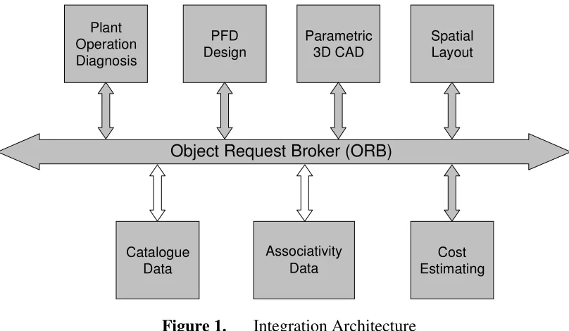
Much research, including an ongoing project at the EDC [1] regarding the integration of diverse sets of design tools and data across heterogeneous distributed computing systems, has focused on the use of STEP [2] compliant product data models and CORBA [3] based communication as illustrated schematically in Figure 1. This technology is relatively mature, and is beginning to be applied within large engineering organisations, but its scope for further development may be limited. XML [4] is now emerging as a technology that could offer the potential for more dynamic integration, able to adapt more rapidly to changes.
Object Request Broker (ORB)
Catalogue Data
Cost Estimating Associativity
Data PFD
Design
Spatial Layout Parametric
3D CAD Plant
[image:3.595.96.500.367.602.2]Operation Diagnosis
Figure 1. Integration Architecture
Much of the research in this area is based on the use of agents, which are generally used both to provide elements of what is essentially integration functionality (i.e. facilitating communication between different tools) and to provide higher levels of functionality, including:
• co-ordination
• conflict resolution
Whilst much of this research remains in the academic sector, it should be noted that commercial products are beginning to emerge which provide some of this functionality [5].
4. EDC Integration and Co-ordination Research
As noted above, the research portfolio of the EDC has included several projects focused on the development of integrated engineering environments under the ‘integration and co-ordination’ theme. The current research activity is illustrated schematically in Figures 2 and 3.
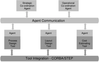
Figure 2 illustrates schematically how an agent communication layer is built on top of the integration layer shown in Figure 1 in order to facilitate the communication of higher grade information (‘knowledge’) between agents. In this project KQML [6] is used as the agent communication language.
Operational Co-ordination
Agent Strategic
Co-ordination Agent
Process Design
Tool Agent
Layout Design Tool Agent
Cost Estimating
Tool Agent
[image:4.595.89.506.281.542.2]Tool Integration - CORBA/STEP
Agent Communication
Figure 2. Integration and Co-ordination Architecture
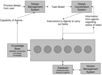
Figure 3 shows some of the key features of the overall EDC research effort in this area, namely:
• Distributed product data model: the STEP compliant product data model shared by the design agents.
• Distributed knowledge base: the higher grade information shared by the design agents, communicated using KQML.
• Design Co-ordination System: a set of agents, which ensure that these tasks are carried out as efficiently as possible, in an environment of dynamically varying resource availability.
Design Management
System Process design
from user Task Model
Design Coordination
System
Agents
Knowledge Base
Capability knowledge and design knowledge
Capability of Agents Instructions to Agents to carry out tasks
Information from agents regarding status of tasks
Database
Distributed data shared by agents
Version Management
[image:5.595.95.500.129.429.2]System
Figure 3. Information Flows in Integration and Co-ordination System
These models are being developed and validated in a series of case studies in different LMTO sectors. Specific aspects of the work have made use of real-world design tools and problems from offshore, power generation, marine and aerospace sectors.
The following section of this paper discusses one aspect of the work, the design co-ordination system, in more detail.
5. Enabling Concurrent Engineering through Design Co-ordination
5.1 Introduction
teams are independent but cannot work in isolation since communication must occur between them. For complex product development, CE not only needs multi-functional teams, but also requires communication between teams and effective co-ordination to integrate their efforts. Hence, a communication environment is required to allow effective sharing of information between teams and among team members of related development tasks.
Many issues have been identified as essential requirements with regard to ensuring that CE is effective when implemented and operated in a large engineering organisation or complex design process. The most prominent issues of CE are co-ordination, communication, cooperation (teamwork), integration, information sharing, multi- functional teams, planning, scheduling, self-discipline and productivity [11-16].
It is argued that co-ordination is the principal requirement for the successful implementation of CE. Co-ordination can be thought of as the concept of the appropriate activities being performed, in a certain order, by a set of capable agents, in a fitting location, at a suitable time, in order to complete a set of tasks. That is, for the right reasons, at the right time, to meet the right requirements and give the right results [17].
5.2 Concurrent Engineering
The emphasis of much research has been directed toward the belief that organisations need to realise that in order to be successful now, and in the future, approaches and techniques to modernise its structure, and the way in which it operates, need to be continuously reviewed. If a competitive edge in the global marketplace is to be maintained, such continuous reviews need to be carried out voluntarily, rather than just when pressured to do so. Organisations failing to respond to the perpetual changing approaches to engineering design will result in them becoming uncompetitive.
CE is seen as one such approach that companies could employ if they are aiming to perform to their optimal potential. A forward thinking and progressive organisation will appreciate and understand the prominent issues of CE mentioned previously. Proper implementation and co-ordination of CE due to its systematic nature will ensure a more efficient and effective organisation. The size and nature of a business needs to be taken into account when deciding how, and to what extent, CE could be employed within the organisation.
members and also between groups. McCord et al [9] define CE as multiple cross-functional teams, rather than cross-functional groups, working simultaneously on separate aspects of the overall development effort. Integration, co-ordination and information flow are identified as challenges of CE. Tomiyama [10] identifies the critical issues of performing CE in industry as (i) constructing cross-functional teams that are focused on the target product, (ii) facilitate mutual communication among members of cross-functional teams, (iii) bringing traditionally later stages of the design process to the discussion table early, and (iv)develop a computational infrastructure to facilitate (i), (ii) and (iii). Gatenby et al [11] describe a systematic approach and offer the basic elements of CE as cross-functional teams, concurrent product realisation process activities, incremental information sharing and use, integrated project management, early and continual supplier involvement and customer focus. Matta et al [12] describes a generic model for the CE task with three main subtasks. The first being the design subtask which relies on private knowledge and each designer generating some propositions to satisfy given requirements. Secondly, the argue subtask attempts to change other participants opinion by justifying the utility and the necessity of a proposition. The third subtask being where groups evaluate the integration of propositions. Conflicts arise when propositions do not satisfy participant’s needs. The primary task here is to detect and solve conflicts.
CE has become one of the more prominent contemporary strategies aimed at making an organisation more competitive in today’s aggressive commercial markets. CE needs to be supported and sustained in order to achieve the long term benefits it offers. Inadequate implementation and co-ordination will result in the organisation failing to realise the benefits and give CE little opportunity of succeeding. The principles of CE must be fully understood and embraced by an organisation if implementation is to be successful. Implementation may also be time- consuming and costly but the long term benefits of the full impact of the strategy are aimed at creating a stronger organisation. The applicability of CE must also be given careful consideration as it may not be plausible in a particular situation or even appropriate. That is, CE may only be applicable in certain areas of the design process whereas the more traditional sequential approach may be required in other areas. Some activities should not be performed concurrently and if they are then there exists the risk of major re-work. Therefore, CE must be performed sensibly in that activities should only be carried out concurrently if it is realistic and advantageous to do so. Great effort should be taken to ensure that CE is utilised wherever possible providing the reasoning behind such a strategy aids the design process as a whole.
5.3 Requirement for Design Co-ordination
CE is concerned with the concept of performing activities simultaneously which are usually carried out sequentially. However, CE does not remove or shorten the duration of some sequential activities from the design process but brings together sequential activities and focuses on concurrent considerations in order to establish which activities can be performed simultaneously. Clearly, the concept of CE is attractive with obvious benefits and advantages. In order to be able to take advantage of concurrency at any level, an appropriate mechanism needs to be in place that enables any potential opportunities of simultaneity to be maximised and realised. Co-ordination is proposed as the principal key to such a mechanism.
needs to be performed so that the appropriate task can be completed. The activity needs to be specified such that when performed will have the desired effect and complete the task. Therefore, careful consideration needs to be given to determine which activity it is most appropriate to carry out in order to do the task. To perform an activity, an agent, or agents, must carry out the required actions in order to complete a particular task. An agent can be considered as a resource and may be human, software or hardware. Essentially, an agent is an entity capable of performing some activity to do a given task. The correct choice of agent, or agents, will ensure that the activity is performed in the most suitable fashion and the task is completed satisfactorily. Since relationships can exist between tasks, there may be an optimal order in which activities should be performed to complete the tasks. Consideration to this fact will assist in identifying those activities that can be performed concurrently and those that must be carried out sequentially. When an agent is performing an activity it may be appropriate to do so in a certain location. This consideration may be of particular importance and relevance when agents are working in the same team, or related teams, to complete the same task, or related tasks. For any activity, timeliness is usually of paramount importance. The time at which an activity is performed directly affects the completion of a task.
5.4 Agent Oriented Approach to Co-ordination
Co-ordination can be viewed as the decision making, controlling, modelling and planning/scheduling activities with respect to the design factors time, tasks, resources and aspects [7], [13]. The agent based co-ordination approach described here embraces this high level concept in that it involves the co-ordination of tasks which aims to optimise the scheduling and planning of the design process with respect to the allocation and utilisation of available resources. The approach incorporates an agent architecture in which each agent fulfils a particular role and performs several different activities. The behaviour of all agents is complimentary in that they assist other agents when necessary. Agents communicate by sending messages and take appropriate action when required.
In any application of the agent based co-ordination approach, the number of certain agent types is fixed whereas others are dependent on factors such as the tasks to be completed in the design process and the available resources in the design environment. Only one Co-ordination Manager (CM), Resource Manager (RMan) and Scheduling Agent (SA) exist. The number of Information Managers (IM) is equivalent to the number of different tasks to be completed. The number of Task Managers (TM) is equal to the product of the number of tasks and the number of resources. Each resource being utilised is allocated a Resource Monitor (RMon) and an Activity Director (AD).
• The Co-ordination Manager registers agents and provides an introduction service such that related agents can locate each other.
• The Resource Manager is responsible for ensuring that at all times optimal utilisation is made of the available resources in the design environment.
• Activity Directors act on this schedule by directing Task Managers to complete their tasks by performing the required activities.
• Prior to executing their tasks, Task Managers request input from their related Information Manager.
• Resource Monitors constantly review their associated resource and inform the Resource Manager of any change.
5.4.1 Co-ordination Manager
Initially, the Co-ordination Manager is central to all agent activity. In order for an agent to register its services, firstly it must send a message to the Co-ordination Manager. Information contained within this first communication relates to attributes of the agent. This information, which is dependent on agent type, is registered by the Co-ordination Manager in an address book. Once an agent’s attributes have been recorded, the Co-ordination Manager acknowledges the existence of the said agent. Subsequently, in the event of any one agent requiring particular information regarding another agent, the details can be obtained from the Co-ordination Manager. Knowledge of this information then enables the necessary agents to communicate directly, rather than via the Co-ordination Manager, and work cooperatively to perform their activities, complete their tasks, and achieve their goals. This feature of agents having the ability to communicate directly with any other agent allows efficient message passing, removes the problem of communication bottlenecks, and promotes co-ordination. Message passing is said to be efficient since communication only occurs when necessary between agents. The Co-ordination Manager facilitates the decentralisation of communication amongst agents. Consequently, message bottlenecks are avoided and communication can occur directly and concurrently between agents, rather than via some centralised agent. Co-ordination is promoted since the Co-ordination Manager can supply related agents with each others details such that the agents can then work cooperatively as a team to meet the overall objective.
A number of agents request information from the Co-ordination Manager regarding other agents such that they can communicate directly and coordinate their activity. Specifically, each Task Manager requests the address of its related Information Manager. These agents are related if they are associated with the same task. If the Information Manager has registered, the Co-ordination Manager provides the Task Manager with the requested information. In the situation where the Information Manager has not yet registered, the Co-ordination Manager indicates to the Task Manager that it should request the information again at a later time. This period of time may be specified by the Co-ordination Manager. Similarly, the Scheduling Agent, Resource Monitor, and Activity Director agent types request the address of the Resource Manager. These requests are managed by the Co-ordination Manager in exactly the same manner as described with the Task Manager and Information Manager.
CM IM TM RMan SA RMon AD
CM 1 1 1 1 1 1
IM 1 1 0 0 0 0
TM 1 1 0 0 0 1
RMan 1 0 0 1 1 0
SA 1 0 0 1 0 1
RMon 1 0 0 1 0 0
[image:10.595.181.417.72.188.2]AD 1 0 1 0 1 0
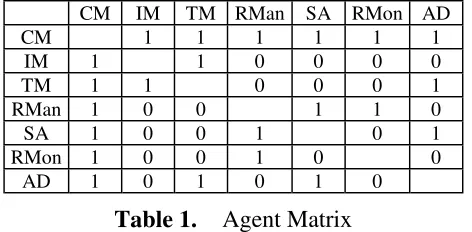
Table 1. Agent Matrix
The matrix contains information regarding relationships between all registered agents and, hence, the communication links between them. An element equal to 1 indicates that a relationship exists between the respective agents. If an element is 0 then no relationship exists between the agents.
In the event of the Co-ordination Manager becoming unavailable, the information contained within the agent matrix can be ascertained by its replacement. The replacement agent would be able to perform all duties originally performed by the Co-ordination Manager.
An agent replacement mechanism exists which enables any agent that becomes unavailable to be replaced such that the effectiveness of the agent community is not compromised and the performance of the co-ordination is not diminished. Unless, the agent that has become unavailable is the ordination Manager, then it is the Co-ordination Manager who operates the agent replacement mechanism. New agents are integrated into the society of agents with minimal impact on all other agents and the design process.
5.4.2 Information Manager
An Information Manager is directly associated with a particular task. Responsibilities of this agent include ensuring that inputs are coordinated before and after the associated activity is performed on them. That is, they are added to or removed from the right resource at the right time. Other duties include ensuring that any information and/or tools associated with the task to which it has been assigned are made available to the related Task Manager. After a Task Manager has performed its associated activity to complete its task on a particular input, and prior to preparing another input, the Information Manager coordinates the output from the previous task. That is, the output may be removed from one resource and placed on another as input in preparation for the next activity to be performed. This procedure needs to be carried out after every activity is performed to avoid delays on any of the resources.
An Information Manager needs to be able to provide a specifically requested input to the Task Manager while keeping a record of those inputs that have already been released and those pending. This is due to the order in which inputs are scheduled by the Scheduling Agent not necessarily being in ascending numerical order of input identification number. Hence, a Task Manager may wish to request a specific input.
5.4.3 Task Manager
Once a task has been completed by a Task Manager the related Information Manager coordinates the output. Inputs continue to be requested from the Information Manager by the related Task Manager until all have been dispensed and each activity has been performed on them, and hence all tasks have been completed. That is, the design process is complete.
Task Managers need to be able to request a specific input from their respective Information Managers so as to accommodate the ‘random’ order of inputs within any given schedule as calculated by the Scheduling Agent. Hence, the input identification number is recorded which can be checked by the Activity Director prior to the activity being performed. An Activity Director is responsible for ensuring that the appropriate activities taking place on its associated resource are carried out in the correct order at the right time by the right Task Manager. Hence, a Task Manager will be instructed at the appropriate time to commence performing an activity on a particular input by an Activity Director. Each Task Manager must act promptly when instructed to commence by an Activity Director. This prompt action will lead to the schedule being adhered to as closely as possible and the design process being completed in a near optimum time.
5.4.4 Resource Manager
The Resource Manager is responsible for managing the available resources. The main functions of this agent is to construct and maintain a resource model.
The resource model contains a status flag Sj and an efficiency measure Ej, where j = {1,2,3,...,m} and m is the number of resources within the design environment, as shown in Table 2.
Resource Status Efficiency
R1 S1 E1
R2 S2 E2
R3 S3 E3
... ... ...
[image:11.595.218.378.420.514.2]Rm Sm Em
Table 2. Resource Model
A status flag is an indication of whether or not a resource is available for use, such that Sj = {0, 1} ∀ j. Efficiency is a relative measure of the speed of a resource, such that 0 ≤ Ej ≤ 1 ∀ j. The Resource Manager updates the resource model when necessary following notification of a shift in a particular resource’s efficiency by the associated Resource Monitor.
the Scheduling Agent to proceed in doing so. This decision making process concerning whether or not to re-schedule, involves the Resource Manager taking into account several factors. The number of inputs remaining to be considered and the likelihood that a new schedule will be adhered to for the remainder of the design process should also be taken into account.
5.4.5 Scheduling Agent
A Multiple Criteria Genetic Algorithm [18] is utilised by the Scheduling Agent to facilitate the optimum utilisation of the available resources. The Scheduling Agent views the scheduling problem as the total design time, of a given number of tasks with interdependencies between them, should be minimised by assigning them to be performed on an optimum number of the most efficient resources.
The Scheduling Agent prepares the information required for the Multi Criteria Genetic Algorithm (MCGA). This information is held in a task matrix and the resource model.
The task matrix, as used by Eppinger et al [17], is constructed by the Scheduling Agent. This matrix contains information such as dependencies between tasks Ti and datum task durations TDi, where i = {1, 2, 3,..., n} and n is the number of tasks. Task dependencies are represented in the off-diagonal elements by 0 for non-dependency and 1 for dependency. Datum task durations, using consistent units, are represented in the diagonal elements. An example task matrix is shown in Table 3.
T1 T2 T3 ... Tn
T1 TD1 0 0 0 0
T2 0 TD2 0 0 0
T3 1 1 TD3 0 0
... ... ... ... ... 0
[image:12.595.213.384.378.471.2]Tn 0 1 0 0 TDn
Table 3. Task Matrix
The Scheduling Agent uses the information held in the task matrix to identify those activities that can be performed simultaneously such that the corresponding tasks that can be completed concurrently.
5.4.6 Resource Monitor
A Resource Monitor exists for each resource within the design environment. Each Resource Monitor continuously monitors and records the efficiency and status of its associated resource. If a Resource Monitor observes its associated resource’s efficiency deviate from the current value or the status change, then it will inform the Resource Manager of this fact and supply the latest statistics. This may result in the Resource Manager deciding to remove/add that particular resource from/to the design environment and request that a new schedule be calculated by the Scheduling Agent.
5.4.7 Activity Director
As with a Resource Monitor, an Activity Director exists for each resource within the design environment. An Activity Director is responsible for directing the activities to be performed on its associated resource in order to complete the corresponding tasks. This agent also facilitates the operational co-ordination of the tasks and resources involved in the design process.
Each Activity Director must orchestrate the activities being performed on its associated resource. In particular, an Activity Director is responsible for instructing Task Managers to perform their associated activity on a particular input on the associated resource in the appropriate order. A Task Manager will only be able to perform its associated activity if permission is given by the Activity Director. Once the Task Manager receives this instruction it proceeds to perform the activity on a given input. On completion, the Task Manager informs the Activity Director that it has finished. The Activity Director then proceeds to instruct the next Task Manager in the local schedule to perform its activity on a particular input, and so on.
5.5 Application
The application considered involves the DCS being utilised in conjunction with the Robust Concept Exploration (RCE) framework [19]. The RCE framework employs Taguchi methods, analysis tools and state-of-the-art statistical techniques such that an efficient exploration of the design space can be conducted in order to locate designs, which are considered to be robust. Briefly, a design is said to be robust if its performance is insensitive to the environment in which it is manufactured or operated.
to the greatest proportion of the overall operation of the RCE framework. Benchmark results were obtained by employing the RCE framework in a Unix environment on one Ultra 1/170 machine, which has a single UltraSPARC processor. The benchmark execution times recorded were for the sequential execution of the analysis tool alone, rather than including the use of Taguchi methods and statistical techniques.
Subsequently, the DCS was employed in the same Unix environment with the design analysis, involving the evaluation of alternative catamaran design concepts, being carried out on various combinations of Ultra 1/170 machines, namely 1, 2, 3, 4 and 5. DCS agent activity was performed on an Ultra 10 Workstation which has a single processor. The co-ordinated approach, implemented within the DCS, was assessed such that its effect and that of varying the number of processors could be established. Benchmark and DCS measurements were obtained from two cases involving the evaluation of 79 and 243 catamaran design concepts.
5.6 Results
Prior to discussing the results achieved in the catamaran design example, it is appropriate to mention the actions of the agents employed within the DCS. Once the RCE framework generated a number of alternative concept designs to be evaluated, the DCS was invoked. Initially, the Co-ordination Manager received notification of registration from all other agents, which included details of their attributes. Each agent then requested information from the Co-ordination Manager regarding related agents such that they could communicate directly thereafter. The Resource Manager was initially contacted by all Resource Monitors, which provided current measures of efficiency for the processor to which they were associated. Simultaneously, the Scheduling Agent constructed a task matrix, which held information regarding the tasks that need to be completed, i.e. the design concepts to be evaluated. Based on the information within the task matrix and resource model, the Scheduling Agent then employed the MCGA in order to determine a near-optimum order in which catamaran concept evaluations should be performed on the available processors taking into account their respective efficiency measures. The MCGA produced a Pareto optimal set of schedules, each of which was near optimal with respect to certain criteria. Minimise (1) time to complete the concept evaluations, (2) number of processors used, and (3) mean processor utilisation, were used as criteria to select the ‘best’ schedule. The relevant part of this ‘best’ schedule was then communicated to each respective Activity Director of the corresponding processor such that the analysis could commence. Activity Directors associated with each processor then requested that their related Task Manager of the corresponding design concept complete the concept evaluation. Prior to the completion of the concept evaluation, Task Managers requested that their related Information Manager provide the appropriate input information for the particular design concept to be evaluated. As soon as this information was supplied, the Task Manager completed the concept evaluation. Subsequently, the related Information Manager recorded the results of the evaluated design concept. The Activity Directors then continued directing the analysis in accordance with the schedule for their associated processor until the whole design analysis was completed.
Benchmark results were obtained using a single Ultra 1/170 machine to sequentially compute 79 and 243 concepts for Case 1 and Case 2 respectively. The results presented in Table 4 were obtained by running the DCS in comparable conditions for each operation with respect to processor utilisation. That is, it was ensured that other network usage was negligible.
Table 4. Design Co-ordination System - Performance Measurement
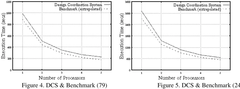
Figures 4 and 5 indicate the total time taken for the family of agents operating within the DCS to perform their individual activities including the analysis tool execution duration for all design concepts being evaluated. Extrapolated benchmark execution times are also shown. The inverse relationship between the number of processors and computation time was used to obtain extrapolated results for 2, 3, 4 and 5 processors. Therefore, using n processors as opposed to 1 should result in a 100(n-1)/n% reduction in computational time. With respect to the extrapolated benchmark execution times, the assumption is made that for each combination of processors, all processors are working in parallel with an equal number of design concepts being evaluated sequentially on each of them.
Figure 4. DCS & Benchmark (79) Figure 5. DCS & Benchmark (243)
since there would be no requirement for the DCS if only one processor were available as its intended use is in a distributed computing environment. The need for operating the DCS can only be justified in the event of more than one processor being available. After discarding the single processor use of the DCS, it can be deduced from Table 4 that a relatively small offset range of 7.2% to 4.5% envelops both cases. This proportion of DCS operation is due to activities performed by agents excluding analysis tool executions by Task Managers. Prior to any analysis tool execution, the Information Manager is tasked with preparing and coordinating the various design concept models throughout the distributed design environment. Similarly, evaluated concepts need to be coordinated for subsequent use, in this instance within the RCE framework, between analysis tool executions. In addition, certain activities of the Co-ordination Manager, Scheduling Agent, Resource Manager and Resource Monitors need to be performed before any analysis tool executions can commence.
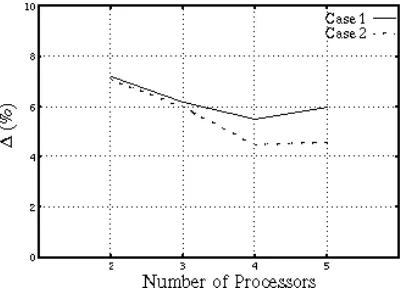
[image:16.595.197.400.308.455.2]In Table 4 it can be seen that a marginal difference in offset exists between Case 1 and 2. This difference is illustrated in Figure 6.
Figure 6. Offsets: Case 1 & Case 2
The discrepancy between the two cases can be explained by the fact that the proprtion of coordination activity performed by the agents is less as a total percentage of the overall duration of the DCS in Case 2 than in Case 1. Approximately three times as many design concepts were evaluated in Case 2 as in Case 1 and therefore analysis tool computation time becomes more dominant. Hence, the greater the number of design concepts being evaluated , the less the offset between the DCS and benchmark results.
5.7 Summary and Conclusions
The DCS has achieved significant reductions in the time taken to perform the computational analysis of a given number of design concepts within the RCE framework. Essentially, the time compression achieved by the DCS is inversely proportional to the number of processors utilised. As a result of significantly reducing the design analysis time, utilising the DCS has allowed the designer to perform a more comprehensive concept exploration of the design space. Consequently, the concept design selected was superior in terms of the designer’s nominated criteria [20].
time to be reduced by seizing the opportunity to perform activities concurrently. Simply committing greater resources to a particular part of the design process will not necessarily result in a corresponding reduction in the time to perform the tasks involved. It is the capacity to coordinate the activity performed by each of the team members, taking into account the available resources and knowledge of their roles and effects, and taking advantage of instances where concurrency is possible that enables a measured reduction in the duration of those activities to be achieved.
References
[1] McAlinden L.P., Florida-James B. O., Chao, K-M, Norman P., W. Hills, & Smith P., ‘Information and Knowledge Sharing for Distributed Design Agents’, conference proceedings of AI in DESIGN’98, Lisbon, Portugal, 1998.
[2] Owen, J.: 1994, STEP An Introduction, Information Geometer Ltd., Winchester, UK.
[3] Object Management Group (OMG): 1995, The Common Object Broker: Architecture and Specification Release 2, OMG.
[4] Tidwell, D., Tutorial: Introduction to XML, 12 August, 1999.
[5] “Achieving Competitive Advantage Through Knowledge-Based Engineering – A Best Practice Guide”, Knowledge Technologies International Ltd, 1999.
[6] Finin, T., ‘DRAFT Specification of the KQML Agent-Communication Language plus example agent policies and architectures’. The DARPA Knowledge Sharing Initiative, External
Interface Working Group.
[7] Duffy A.H.B., Andreasen M.M., MacCallum K.J. and Reijers L.N., “Design Co-ordination for Concurrent Engineering”, Journal of Engineering Design, Vol. 4, No. 4, 1993, pp. 251-265.
[8] Tan G.W., Hayes C.C. and Shaw M., “An Intelligent-Agent Framework for Concurrent Product Design and Planning”, IEEE Transactions of Engineering Management, Vol. 43, No. 3, August 1996, pp. 297-306.
[9] McCord K.R. and Eppinger S.D., “Managing the Integration Problem in Concurrent Engineering”,
[10] Tomiyama T., “A Note on Research Directions of Design Studies”, International Conference on Engineering Design, 1997, Vol. 3, pp. 29-34.
[11] Gatenby D.A., Lee P.M., Howard R.E., Hushyar K., Layendecker R. and Wesner J., “Concurrent Engineering: An Enabler for Fast, High-Quality Product Realization”, AT&T Technical Journal, 1994, pp. 34-47.
[12] Matta N. and Cointe C., “Concurrent Engineering and Conflict Management Guides”, International Conference on Engineering Design, 1997, Vol. 3, pp.761-766. [13] Andreasen, M.M., Duffy, A.H.B., MacCallum, K.J., Bowen, J., & Storm, T., “The Design Co-ordination Framework - key elements for effective product development”, Proceedings of the 1st International Engineering Design Debate, University of Strathclyde, Glasgow, UK. 23-24 September 1996.
[14] Winner R.I., Pennell J.P., Bertrand H.E. and Slusarczuk M.M.G., “The Role of Concurrent Engineering in Weapon Systems Acquisition”, IDA Report R-338, Institute of Defence Analysis, 1988.
[16] Steward D.V., “The Design Structure System: A Method for Managing the Design of Complex Systems”, IEEE Transactions of Engineering Management, Vol. EM-28 (No.3), 1981, pp. 71-74.
[17] Eppinger S.D., Whitney D.E., Smith R.P., Gebala D.A., ‘A Model Based Method for Organising Tasks in Product Development’, Journal of Engineering Design, 1994. [18] Todd D.S., ‘Multiple Criteria Genetic Algorithms in Engineering Design and Operation’, Ph.D. Thesis, University of Newcastle upon Tyne, October 1997.
[19] Whitfield R.I., Coates, G., & Hills, W., “Multi-Objective Robust Concept Exploration within the Made-To-Order Sector”, Proceedings of the 12th International Conference on Engineering Design, 24-26 August 1999, Munich, Germany.
[20] Whitfield R.I. & Coates G., “An Application of the Design Co-ordination System within the Robust Concept Exploration Framework”, EDC/N3/REP/RIW/17, January 1999.
Biographies
Graham Coates is presently employed as a Research Associate in the Engineering Design Centre at the University of Newcastle upon Tyne. He is currently conducting research in the area of design co-ordination. Prior to this work he was employed in the aerospace industry for seven years. At British Aerospace he worked on aerodynamic and structural engineering aspects of aircraft development. At Aerospace Systems & Technologies he worked on a European Union funded project on laminar flow technology for commercial aircraft.
Ian Ritchey was Director of the Engineering Design Centre at the University of Newcastle upon Tyne from 1998 to 2000, where he was responsible for the overall research programme of the Centre. Prior to this he worked for Rolls-Royce plc as Chief Engineer of Advanced Systems, where his responsibilities included development and management of research programmes to support design process improvement for power and propulsion systems. He has now returned to Rolls-Royce plc as Head of Research & Development - Marine.
Alex Duffy is presently a Senior Lecturer and Director of the Computer Aided Design Centre, at the University of Strathclyde. He lectures in engineering design, design management, product development, knowledge intensive CAD, advanced computational techniques, and databases. His main research interests have been the application of knowledge based techniques in conceptual design, product and domain knowledge modelling, machine learning techniques and design re-use, performance measurement and design productivity, sketching and vague geometric modelling, and design co-ordination. He has published over 100 papers and is on the board of numerous journals and conferences in engineering design and artificial intelligence in design.