Accepted Manuscript
loTSim-Stream: Modeling stream graph application in cloud simulation
Mutaz Barika, Saurabh Garg, Andrew Chan, Rodrigo N. Calheiros, Rajiv Ranjan
PII: DOI: Reference:
To appear in:
Received date : Revised date : Accepted date :
S0167-739X(l8)3 l 704-7
https://doi.org/10.1016/j.future.2019.04.004 FUTURE4885
Future Generation Computer Systems
20 July 2018 21 February 20 l 9 3 April 2019
FJ3
IC
I
S
1
Please cite this article as: M. Barika, S. Garg, A. Chan et al., loTSim-Stream: Modeling stream graph application in cloud simulation, Future Generation Computer Systems (2019),
https://doi.org/ l 0.1016/j .future.2019 .04.004
IoTSim-Stream: Modeling Stream Graph Application in Cloud Simulation
Mutaz Barikaa,*, Saurabh Garg 3, Andrew Chan a, Rodrigo N. Calheiros band Rr ,. �anjan c auniversity of Tasmania, Australia
bWestern Sydney University, Australia cNewcastle University, United Kingdom (mutaz.barika, saurabh.garg, andrew.chan)@utas.edu.au
R. [email protected] [email protected]
Abstract
In the era of big data, the high velocity of data imposes the demand for proces�. · � ,,uch lata in real-time to gain real-time insights. Various real-time big data platfonns/services (i.e. Apache Storm, Amazon K1,. ·"is) �::Jw to develop real-time big data applications to process continuous data to get incremental results. Composing those aoplicatio1. · to form a workflow that is designed to accom plish certain goal is the becoming more important nowadays. However, 6: ·�n th current need of composing those applications into data pipelines forming stream workflow applications (aka stream gn,r •, appucations) to support decision making, a simulation toolkit is required to simulate the behaviour of this graph applicatirm ;" ,...,�. · computing environment. Therefore, in this paper, we propose an loT Simulator for Stream processing on the big data �1. ·11ed IoTSim-Stream) that offers an environment to model complex stream graph applications in Multicloud environment, v ·-�,·p the la.ge-scale simulation-based studies can be conducted to evaluate and analyse these applications. The experimental results�- 0v chm IoTSim-St:ream is effective in modelling and simulating different structures of complex stream graph applications wit.I- Qxcel1, '1t performance and scalability.
Keywords: Internet of Things (IoT), Stream Processing, Stream 1rai,;1 Applications, Multicloud Environment, Simulator
1. Introduction
In recent years, there is an emergence of "big u. '<i" tf' m
that has been introduced to deal with collecting, ,roCP,SS11,0 and
analysing voluminous amount of data. It ha8 ,hre• cha acter istics known as 3Ys of big data, which are v ,Jun •. rthr size of data), variety (the different types of data co' �cted) anu velocity (the speed of data processing). To transac. with : 'o data, many big data platforms have been developf' ·., -hich allow design ing and building big data analysis ar ,lica· .ons to ingest, pro cess as well as analyse tremendous ::imou. of data. Composing those applications into data analy· .s pi �elint forming big data workflow applications allows de. ·•er' .1g or valuable analytical
insights to make better decisioJ1� � 14 J.
The execution and managf nent of ',ig data workflow applic ation need a dynamic enviror, '1ent th2 provides the underlying infrastructure for big dat? • ·oct�-: .. 5, allowing parallel execu tion of this workflow ap ,Jicatio1. 1nd to exploit large amount of distributed resources. A· Clone computing offers on-demand access to large-scak rP,sOm'l.,c.� mcluding compute, storage and network which can t" ·klf' :;,.,..,nsive computation problems [ 11] [2], it is seen as a visible ,olution for the execution of this work flow application. Even mJre, the Multicloud environment that consolidates multiple Clouds is more visible solution for or chestrating the execution of multiple applications included in such workflow application over various Clouds. Other than util izing these resources, the requirements of big data workflow
applications such as near real-time data analysis need to be en sured. The requirement of orchestration systems that can help in execution and management of big data workflow applications on a Cloud and Edge infrastructure is pointed out by [14] as the most important and cutting edge research issue. Accordingly, the need of understanding the behaviour of these applications when they are executing in Cloud environment and for develop ment of new scheduling and resource provisioning techniques is important to ensure that requirements of these applications can be successfully met while utilising Cloud infrastructure ef ficiently and effectively.
useful software toolkit, allowing both researchers and commer cial organizations to model their stream graph applications and evaluate the performance of their algorithms in heterogeneous Cloud infrastructures at an effective time and with no cost.
To address the above research problems, we design and implement an IoT Simulator for Stream graph applications (IoTSim-St:ream) that extended a popular and widely used Cloud computing simulator (CloudSim), where we model stream workftow application in Multicloud environment. It provides the ability to model and simulate the execution of stream graph application over resources provisioned from vari ous Cloud infrastructures. In summary, the following are our contributions:
• Modelling stream graph application.
• Extending the XML structure of commonly existing non streaming workftow strictures (e.g. Montage, Cyber Shake) to simulate stream graph applications.
• Modelling Multicloud environment as an execution envir onment for stream graph application.
• Proposing a new simulator named loTSim-Stream that leverages the features of CloudSim and integrating real time processing model with workftow scheduling and ex ecution to execute the modelled stream graph application in Multicloud environment.
This paper is structured as follows: Section 2 describe� stream graph application is, while Section 3 outlines design i,, sues of this type of workflow application. Section 4 reviews the related simulation tools. Section 5 presents the? .:hite'" ·ire of the proposed simulator (IoTSim-Stream), whiL ;n Secti m 6, we explain in detail the implementation of Ir TSim-
>·
am including the extended XML structure, propof ;d p· Jvisioning and scheduling policy, proposed stream schedu. · � _ pol" ..:y and proposed YM-level scheduler. Section 7 r .esents v. _ experi ments to validate and evaluate the perfo- ,na,. 0 and scalabil ity of loTSim-Stream in simulating stren'"'l. graph ..ipplications in Multicloud environment, and discu· .;es t .e obtained results. Section 9 concludes the paper and h1b·-1; ,hts future improve ments.2. Stream Graph Applicatior
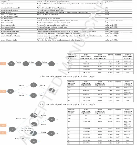
Stream Graph application is a ne Nork of streaming data analysis components, wl--· c ea":. ,ndividual component can be considered as a Sf vice a, i is executed independently
over compute resources ,at p1w isioned from the Cloud, even though data depenrl"'ncies a111ong services should be main tained. Figure I pre. �nt, a1, example of stream graph applic ation with its data proL. <;sing requirements. The execution of this type of workftow api,lication is continuous (i.e. not one time execution). It starts when the data streams generated by ex ternal sources such as sensors being continuously injected into data pipeline (particularly as input data streams to services). The data processing on these input data streams is continuously
2
•
OPReq(SO) UPR(SO)
Replica
Repliu
DPReq(Sl)
UPR(Sl)
•--Partition(],)
Partition(30%)
•
ReplicaL,, IS2)
UPR(S,,
DPRcq(S3) UPR(S3)
•
·
•
DPReq(S4) UPR(S4)Replica
.--;;;.(S5)
UPR(S5)
Replica
DPReq Data Process j Requirement UPR User Performance Requirement EX hternal Source (Data Producer)
Figt... 1 • c, .nple stream graph application
carried-out by , ,ose services to produce continuous output data stream� :: e. O' ,ine insights) that are results of data processing
comp� ·�tions. These output data streams generated by internal
fr"ornno r: parent services) are continuously injected into data
pq,. •;ne, specifically as input data streams to child services, '"hich p. ocess them continuously and then inject the results of co .1pmations into data pipeline. Therefore, we simply can say t, 't this graph application has three main characteristics: con -;nL,ous input data streams from external sources towards con nected services and from internal sources (as results of com putations that routed from these internal sources (i.e. parent services) to child services), continuous data processing of input data streams and continuous output data streams that are results of data processing computations at graph services.
3. Design Issues of Stream Graph Application
Unlike batch-oriented data processing model that intends to process static data (i.e. the amount of input data is finite and it is stored before being processed and analysed) [8] [9], stream oriented data processing model is intended for processing con tinuous data to gain immediate analytical insights. With this model, data arrives in streams, which are assumed to be in finite and are being processed and analysed (in a parallel and distributed manner) as they anive and as soon as possible to produce incremental results at the earliest they are prepared [8] [9]. Based on this model, stream applications have been de veloped to process continuous data to produce continuous ana lytical results. However, given the demand of composing those applications into data pipelines forming stream graph applica tion, this graph application has specific design issues. In the subsequent paragraphs, we will review these issues.
Modeling of graph nodes. - Streaming data applications in
cluded in stream graph application can be considered as ser vices since they can be separately running over any virtual re sources, even though the data dependencies among them should be maintained. These independent processing nodes are al located to appropriate VMs according to their perfonnance requirements for processing continuous streams of data and producing analytical insights at the earliest they are prepared. Therefore, the simulator should models the nodes of graph • , services adhering the data dependencies among them.
Modeling of data flows. - The flow of data in this type � c workflow application is streams, which are infinite continuous events. These streams are continuously injected as : ,pu,� :nto nodes (services) and continuously produced as res· its of co
1-putations, i.e. outputs of nodes (services). The si1"ulall,. 0hr J!d
thus represent this type of data as a sequencr of , vents and allow transmitting them among YMs hosted L_· , ,riot', data centres.
Synchronization of data flows. - In stream grai,. <tpplication,
there exists data flow dependencies acr, aS a alytical nodes, res ulting in the need of data flow synch: ·t1izr .ion. Therefore, the execution of nodes (services) requir :, dy,,� "'ic synchronization of the states ( e.g. output stream of _1arer , service forms the basis of input data stream to one or mOJ .. + .Jd Sf vices) of parent and child services. Hence, the siP-__ ·.Hor �. · uld preserve the syn chronization of data flows as 1t direct. , impacts the correctness of stream graph application e, �cutior
Modelling of Multiclou1 enviro1, -ient and its network perform
ance. - As the executiL , of st:r am graph application will be
carried-out over mp1tin]e L,vud infrastructures, the simulator should model Multi� '0u, t11,ironment as an execution envir onment for this applic. •on. Not only this, but also the exe cution of this application on resources provisioned from mul tiple Clouds means by the way that the streams of data are being transferred between YMs of datacentre (inbound n·affic) or between different YMs hosted by various Cloud datacentres (outbound traffic). Therefore, the simulator also requires to
model the inbound and outbound network performance (i.e. bandwidth and latency) between Cloud datacentres being used during simulation runtime, as tr� amount of streams being transferred is subject to the ava· <ibility of bandwidth and the amount of delay.
4. Related Simulation F1 � ....,e. 1orks
With the emerging of Clo,. ' <:omputing, various simulation based toolkits have r ,en \"'"eloped in order to model the be haviour of different �lor J services and applications on Cloud infrastITtctures. ThP�e s1,. ··lators help researchers in evaluating the performanCf of the� ' systems and applications in control lable environme t.
To the best-• ou,: _ ,v]edge, there is no simulator that model the executi ,n of ,� 1111 graph application in various resources provisioneu: Jm n' ,ltiple Cloud infrastI·uctures. The most re lated simL,. ·•cm, l:',oposed by previous research works are de scribf-d in the L fow paragraphs.
Cloul,,�;,n [:JJ. - It is a popular and widely used event-based
�;,,,,.,MM · .at models and simulates Cloud computing infra st1c. -•ures, applications and services. As an extensible and cus •nmizm.,:e tool, it allows to model custom Cloud application ser vir .;s, �loud environments and application scheduling and pro " 'ioning techniques. In this simulator, users create Cloud tasks '11a,ned Cloudlets) to define their workloads and then submit them to Virtual Machines (VMs) provisioned from Cloud data centre to be processed in the Cloud. The application model of CloudSim is simpler and is more appropriate to simulate batch tasks, so that it is not capable to support stream tasks (i.e. con tinuous computation).
NetworkCloudSim [5]. - It is a simulation toolkit that mod
els Cloud datacentre network and generalizes applications (e.g. High Perfonnance Computing and e-commerce). It allows computational tasks involved in these applications to commu nicate with each other. NetworkCloudSim supports advanced application models and network model of datacentre, allowing researchers to accurately evaluate the new scheduling and pro visioning techniques in order to enhance the performance of Cloud infrastructure. Despite the advanced application models (i.e. multi-tier web application, workflow and MPl) supported by this simulator, the lack of application model that describing big data workflow applications is a major drawback in this sim ulator. Thus, it does not have the capability to simulate stream tasks and even execute stream workflow applications in Cloud environments.
MapReduce Simulators (MRPe,f [17], Mumak [12] [15],
SimMR [16], MRSim [6] and MR-CloudSim [JO]). - MRPerf
and debugging. It takes as input the job trace data from real experiment along with the definition of cluster and then feeds them into simulator to simulate the execution of jobs in the defined virtual cluster with various scheduling policies. SimMR [16] is MapReduce based simulator developed in HP lab. It takes as input the execution traces derived from pro duction workloads and then replies them to facilitate perform ance analysis and evaluating of new scheduling algorithms in MapReduce platforms. MRSim [6] is a discrete event simula tion tool that extends SimJava, a Java discrete event engine to simulate various types of MapReduce-based applications and uses GridSim for network simulation. It offers functionalit ies for measuring the scalability of MapReduce applications and studying the effects of various Hadoop setup configura tions on the behaviour of these applications. MR-CloudSim [10] is a simulator tool for modelling MapReduce based applic ations in Cloud computing environment. It is extended the fea ture of CloudSim to implement bare bone structure of MapRe duce on CloudSim, supporting data processing operations with this model. Thus, MR-CloudSim provides the ability for ex amining MapReduce Model in a Cloud-based datacentre. How ever, these simulators are only intended to support data pro cessing operations with MapReduce model, thus they lack of support for modelling the streaming big data applications and even streaming big data workflow applications.
loTSim [18]. - It is a software toolkit that built on top ol CloudSim to simulate Internet of Things (IoT) applicatic·0 in
the Cloud infrastructure. It integrates loT application mode1 . ' allow processing of IoT data by the use of big data processing platfonn in Cloud infrastructure, providing both r -,ea.... 1iers and commercial entities with the ability to study tJ- , behavil 1r
of those applications in controllable environmer'. 'L ,.: · si' ,u lator is intended to support loT application w· .h W apReuuce model, where it lacks the support for stream c" ''I)' dng 11odel. Therefore, it neither simulate stream big d .ca app.: " .ion nor stream workflow application.
CEPSim {7]. - It is a simulator fr. ev· nt processing and
stream processing systems in the Clv. --1 computing environ
ment. It uses query model to repn' .ent use,· .':'!fined query (ap plication), where the modelled r 1ery l wit'. all its vertices) is
allocated to a YM to be simulateu ' O' ..:e. With such sim
ulator and by default, users .iave t0 determine manually the placements of their queries \ hen suh 1itting them to CEPSim.
Therefore, the main drawhaci-. ,-,f .,1is simulator are (1) the
user-defined query is ex, ..:uted c ,tirely in a single YM, (2) pro visioning resources accl ·ding to 1put event streams of query is
missing and (3) mapping v.· .. " ..• ces to VMs is manual.
WorkfiowSim [4]. - 1. is a simulation toolkit that extends CloudSim to support sci1:.,1tific workflow scheduling and exe cution in the Cloud with consideration of system overheads and failures. It incorporates model of workflow managements sys tems (similar to Pegasus workflow management system) in the Cloud simulation environment, enabling researchers to study
4
and evaluate the performance of workflow opt1m1zation al gorithms and methods more accurately. This simulator is inten ded to support scientific workflov applications, where it lacks the support for big data workfl, '' applications (batch, stream or hybrid). Therefore, it neit! .,r s1, .. ·late streaming big data applications nor streaming bi� : 'ta workflow applications.
Additionally, the com111 ,n/sh .red drawback with all com parable simulators mentione1... 0ove is that they do not lever age the advantages of Mu,.·,iouu environment to execute the modelled application JI, ··esou._es provisioned from various
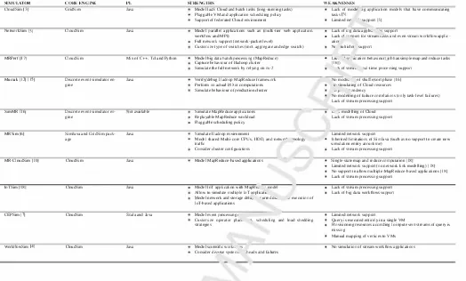
Cloud infrastructun' ,, wJ- �re .:.e proposed simulator supports that. This will open c.. door for further research studies in cluding proposir"' resource and scheduling policies, improving performance an minim1 ing execution cost. The summary of the above mentio. vl si• .ulators along with their strengths and weaknessef are r··,·1ided in Table l.
5. The Pr .. , "Seu Architecture of IoTSim-Stream
The ��'.,udS' ,n is a simulation framework that models and simu1� '� C1oud infrastructures and services [3]. It has rich fea r"·00 ,1-0, · ake it the best choice to be the core simulation en
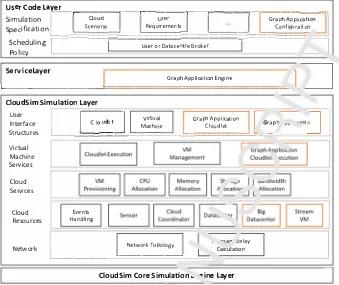
g11,, for our proposed simulator to simulate the behaviour of 0tream 5.-aph applications and their execution in Multicloud en vi• Jnment. Figure 2 shows the layered architecture of Cloud
�-,, with the essential elements of IoTSim-Stream (shown by
'1·a,1ge-outlined boxes). In the subsequent paragraphs, we will
describe these layers.
CloudSim Core Simulation Engine Layer. This layer takes care of the interaction among the entities and components of Cloud Sim via message passing operations [5]. It offers numerous key functions e.g. events queuing and handling, Cloud entities cre ation (such as datacenter, broker), entities communication, and simulation clock management [18]. Entity within the ambit of the CloudSim is a component instance, which could be either a class or group of classes that depicts one CloudSim model (datacenter, broker) [3]. It individually and independently ex ists, and has the capability for sending and receiving events to and from other CloudSim entities as well as process the re ceived ones [18]. Event is a simulation event or message that passes among the CloudSim entities and holds relevant inform ation e.g. the type of event, time at which this event occurs as well as the data passed in this event to destination entity [ 18].
SIMULAH)R
CloudSim [31
NetworkSim 151
MRPerfll7]
Mumak 1121 [ 151
SimMR 1161
MRSim 161
MR-CloudSim [ IOI
loTSim [IKI
CEPSim 171 WorkllowSim 141 CORE ENCINE GridSim CloudSim CloudSim
Discrete event simulator en
gine
Discrete event simulator en gine
SimJava and GridSim pack age
CloudSim
CloudSim
CloudSim
CloudSim
Table 1: Summary of Related Simulators
l'L Java
Java
Mix of C++. Tel and Python
Java
ot available
Java
Java
Java
Scala and Java
Java
STRt�NCTHS
Model laaS Cloud and batch task!! (long-running tasks) Pluggable VM and application scheduling policy Suppon of federated Cloud environment
Model parallel applicaiions such a.'i (multi-tier web applicaiion. workflow and MPI)
Full network suppon (network-packet level)
Customize type of switches (root. aggregate and edge switch)
Model big data batch processing (MapReduce) Capture behaviour of I ladoop cluster Simulate the full netwo.k by relying on ns-2
Verify/debug I ladoop MapReduce framework Perform no actual 1/0 or computations Simulate behaviour of production cluster
Simula1e MapReduce applications Replayable MapReduce workload Pluggable scheduling policy
Simulate I ladoop environment
Model shared Multi-core CPUs, I !DD, and netwr>-' "'?(>logy trallic
Consider cluster conligurations
Model MapReduce-based applications
Model loT application with MapRt� · model
Allow 10 simulate multiple loT .1oplica11 ...
Model network and storage del:.iJ ·rurred a.... ..; execution of JoT-based applications
Model event processing,
Customize operator plac... ·1• scheduling and load shedding strategies
Model sciemific work1. ·1s
Consider divnrse system, .head.i. and failures
WEAKNESSES
Lack of mode-' .1g application models that have communicating tasks 151
Limited ne1 •. 'iuppon [51
Lack of 1,.g data appfo.... "'" suppon
Lack of-.. ..,oon for stream 1-sks and even stream workllow applic
atior
Ne julliclot suppon
L11o. ''l" jicatioo behaviour(job ha.'i simple map and reduce tasks 111,J)
·I( of s1rea,. �al-time processing suppon No mock,. <:>f shuflle/sort phase I 161
ln <:imulating of Cloud resources
"J" ··-�ndency
No modelling of failure correlations (only ta. .. k-Jevel failures) Lack of stream processing suppon
1... , modelling of C.loud Lack of stream processing suppon
Limited network suppon
Inherited lirni1a1ions of SirnJava (such as no suppon IO create new simulation entity at runtime)
Lack of stream processing suppon
Single-slate map and reduce compu1a1ion J IKI
Limited network support (no network link modelling) 118]
No suppon 10 allow multiple MapReduce-based applications [ 181 Lack of stream processing suppon
Lack of stream processing suppon Lack of big data work flows suppon
Limited network support
Query is executed entirely in a single VM
Provisioning resources according to input event streams of query is missing
Manual mapping of venices IO VMs
No simulation of stream work:flow applications
Service Laye,: This layer concentrates on orchestrating the" ·
-ecution of streaming data applications included in stream graph application.
• Graph Application Cloudlet Execution - It executes the submitted cloudlet (i.e. ServiceCloudlet) on YM.
User Code Layer. This layer consists of tw0 sc.· lay rs, Scheduling Policy and Simulation Specificatior, prr 1idin5 the
ability for users to specify their simulation cc ·fig· rati, ,s and
scenarios in order to validate their schedulir _, and i,. �, .sioning
algorithms [5].
The descriptions of loTSim-Stream elements a,_ as follows:
• Graph Application - It is a DireC'' -!d A yclic Graph (DAG) that represents a graph application.
• Graph Application Configu -ttio, - I' defines simulation runtime, application and user rto,,"'irf .nents.
• Graph Application Eng 1e (Grai- 1AppEngine) - It parses DAG input file and ham ... '� th,. whole execution process of graph applicati, .1. Th;s process includes provision ing YMs from difl rent pro iders, scheduling services of graph application on .'·0 ,..,,. ,visioned VMs and the submis sion of graph"· .,.: . • :,..n cloudlets to those YMs.
• Graph Applicatio1. Cloudlet (GraphAppClouldlet) - It represents a graph application with multiple stream applic ation nodes (i.e. services).
• ServiceCloudlet - It represents a generalized stream ap plication node ..
• Big Datacenter (BigDatacenter) - It represents a Cloud re source whose has a list of virtualized hosts, offers various flavours of YM, where the provisioned YMs are allocated on these hosts.
• Stream VM (SYM) - It represents a Cloud resource where the mapped ServiceCloudlet will be executed on it.
6. Implementation
As we mentioned before, the proposed simulator (loTSim Stream) extends CloudSim with new functionality to support modelling the execution of stream graph application in mul tiple Cloud infrastructures. In line with the aforesaid design issues and requirements, the implementation of this simulator consists of two parts, which are modification and addition. The modification part is to modify the original code of CloudSim components such as datacenter and YM. While addition part is to add more components to meet the new requirements such as GraphAppEngine.
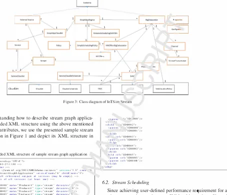
Figure 3 shows the class diagram of IoTSim-Stream. The components with orange-outlined boxes as shown in this figure can be classified either into an entity or a class as follows:
[image:6.595.39.563.104.420.2]Usercodelay
re_r_-i-----,----i-----,--�����---.������=.,
Simulation C
loud User Graph Appli cation
Specification
\:==�=
Sc
=
e
=
na
=
ri
=
o
��:::;;�
R
;;
e
;;
qu
;;
i
r ;;
e
;;
m
;;
en
;;
ts
�:::;;�;;;;;;;;;�!::::�=
C
= o =
nf
= ig =
ur =
a =
tio
:"
n
Scheduling
I
UserorDat acentreBroker
_I
Policy
L_se_rv_ic_e_l_a_ve_r _____
___!:
===================-
Graph Application Engine1
.
�
__J
Cloudsim Simulation layer
User Interface
Structures L __ _::I =C=lo=ud=le=t='....l ...==V=
i
r tu=
a
=
l =
=----==
Gr=a=p
=
hA= p=pl=ica= t=io=n =�
I.._ �
G
:ph e, '"ol I
Machi ne Clo udlet I ( _
Virtual Machine Services
Cloud Services
Cloud Resources
Network
Events Handling
Network T apology L_ Ca1culation . �c;a,... Jelay
L_ ____
___::======--____'.=-CloudSim Core Simulation � ·-,ine layer
Figure 2: The proposed architecture of loTSim-St1, Tr \CloudSim with loTSim-Stream elements)
GraphAppEngine: It extends SimEntity to hand1 1he
execution of stream graph application. That is : · eluding workflow provisioning and scheduling, Data
Producers (DPs) starting-up and shutting-r' J". and
simulation shutting-down based on pre-r· .::fined s1
1-ulation time.
BigDatacenter: It extends native D· cace .cer, ·vhich is an SimEntity, to support sim·1lat. , of stream
graph application that includes h ridling 01 /Ms and transferring streams in betweer Vfv1� �11d out of this datacentre to other datacentr<'·
External Source: It extenc Si• ,Entity to represent any king of DP connect!:' : to th'- �'lta source such as sensor, device or applic .cion 1nd P"enerates a continu ous data stream.
• Classes for modelling ulticlou, environment
VMOffers: Ir ,s an ?bstract class that encapsulates VM instance )ptions ( ffered by different Cloud ser vice providers ·•rh ..1s Microsoft Azure, Amazon EC2 and •v-v'� rompute Engine. Each implement
ation of thi� .,J .;tract class represents the VM options offered by a p. -ricular Cloud provider.
VMOffersBigDatacenter: It extends VMOffers ab st.ract class to encapsulates different VM options offered by a particular Cloud provider (i.e. a Big Datacenter).
6
SVM: It is an extended class of the core VM object to model a VM with input and output stream queues, to be a Stream VM.
ProvisionedSVM: It is a class designed to encapsu late a provisioned SVM with its information includ ing the start and end time, and the cost.
• Classes for modelling basic BigDatacenter network
Channel: It is a class designed to represent a chan nel, which can be either ingress channel for trans mitting streams between SVMs located at the same datacentre or egress channel for transmitting streams among SY Ms located at different datacentres. It con trols the amount of data transmitted in a shared data medium. Each channel, whether ingress or egress, is a shared channel among different simultaneous stream transmissions (time-shared mode).
StreamTransmission: It is a class represents trans mission of a stream from source SVM to destination SVM located at the same datacentre or at different datacentres.
• Classes for modelling stream graph application
GraphAppCloudlet: It is a class designed to repres
[image:7.595.131.470.82.367.2]Service: It is a class designed to model atomic node in stream graph application as a service that pro cesses incoming data stream(s) and produce output stream. It contains service infonnation including service identification, data processing requirement, user performance requirement, its ServiceCloudlets, dependencies streams, parent service(s), child ser vice(s) and output stream.
ServiceCJoudlet: It is an extended class of the core Cloudlet object to implement an atomic graph node, which will be submitted to the Cloud datacentre (i.e. BigDatacenter) by GraphAppEngine and executed in SVM. The atomic graph node or service can be mod elled using one or more ServiceCJoudlets. That is allowing parallel execution of service computations, and enhancing scalability and overall execution per formance while meeting user performance require ments easily. Of course, each ServiceCJoudlet con tains the information of service to which it belongs. Stream: It is a class designed to model data unit that being processed in this simulator. This class is used to represent both stream and stream portion when the original stream splits into several portions.
• Classes for scheduling ServiceCloudlets
Policy: It is an abstract class that implements the aL stract policy for provisioning resources and schedul ing of stream graph application (represented in:.. <::
in an IaaS datacentre. This class performs com mon tasks such as parsing the XML file rlescrib ing the DAG, printing the scheduling pl· 11, am. ··e turning provisioning and scheduling dee •. ''1ns to 1 1e
GraphAppEngine.
SimpleSchedulingPolicy: It is aP extr .1decl class from policy abstract class that r ,pre,,. �ts .ne im plementation of simple provisio .,g and scneduling policy for stream graph applicdtion�. Tt is first re sponsible for selecting the P" J� suitable SVMs for
each service whose achie, ,d u' ..:r performance re quirement, and then scherlul11,0 ·lie ServiceCloudlets
of this service on them f ,r eY :cutio11. The detailed of this scheduling polic1 ·liat offe· ..:d in our simulator will be discussed in thP ne;,.. -� Aion.
ServiceCloudletSc 1eduler. Tt is an extended class of the core Cloudlet� ·'1eduk. object to implement a
space shared .c ... ,dulmg policy performed by SYM
to run Servic ,Cloudlt. The detailed of this sched
uler will be diL ·•1ssecl .n the next section. • Class for scheo. 1mg ,. .. .1ms on SVMs
StreamSchedt. ·;ngOnSYMs: It is a class designed to schedule the divided portions of each stream either input or output stream on SVMs of destination ser vice according to their computing power.
• Classes for customizing simulation parameters
Properties: It is an enumeration class represented the customizable parameters from simulation that are defined in simulation p· :3perties file (named simula tion. properties).
Configuration: It is a clas� 'mplements properties manager, which 1, dds :imulation properties file (i.e. simulation.prop .. +ies' contained parameters of sim ulation that arc -ustu .. '7.ed by users.
6.1. Extending XML. ·v, cture of Synthetic Workjf.ows
Common wor· .rlow s···ucrures from different application do mains [l], such <J.s Mon1 ,ge in Astronomy, Inspiral in Astro physics, Epi�prio, .. '-0 �.1 Bioinformatics and CyberShake in
Earthquake �cier -. ')perate on static data inputs and produce fi nal outputs. 'T'' .crefr e, the XML structure generated by a set of
synthetic . ·,.,rkL ., generators is describing these static work flows and its i, rameters. However, the use of these workflow structu .. - to si 11ulate stream graph applications is practically feas1u: • as t:ach job is considered a service and the data flow r,P"""" 0
• cams of data. The inputs of a job incoming from
ste1." - files (not from parent jobs) become the continuous inputs "fa se1. ice from DPs (i.e. external sources). The service con tiP .,ou�ly processes incoming data streams and continuously J., ,duces output stream. The output of a parent job, which is -,.,nc to one or more child jobs, becomes the continuous output of a parent service that is sent to one or more child services.
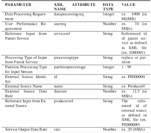
Accordingly, there is a need for extending the original struc ture of those workflows to describe the additional parameters and attributes of stream graph applications such as data pro cessing requirements, input and output data rates. By making this extension, those workflow structures become stream graph structures. Table 2 lists the parameters and attributes being used in the extended XML structure.
Table 2: Additional Parameters of Stream graph Application
PARAMETER XML ATTRIBUTE DATA VALUE
A 1E TYPE
Data Processing Require- dataprocessingreq Integer ex. IO<Xl (in
ment Ml/MB)
User Performance Re- userreq Number ex. 10 (in
quirement MB/s)
Reference Input from serviceref String Referenced id
Parent Service of parent
ser-vice as defined in XML file (ex. IDOCXJOI)
Processing Type of Input processingtype String replica or
par-from Parent Service tition
Partition Processing Type partitionprecentage Integer I -99
for Input Stream
External Source ldenti- id String ex. PIDOCXXJO
fier
External Source Name name String ex. Producer<)
External Source Data datarate Number ex. 12.5 (in
Rate MB/s)
Reference Input from Ex- producerref String The
refer-temal Source enced id of
external source
as defined in
XML file (ex. PIDOOOOO)
[image:8.595.304.560.535.760.2]SimEntity
....
'--�
=
---
'
I
Pm:::]\
\
'
r-
-
=1
VMOffers
Stream Streamlransmission
1...*
CloudSim doudlet doudletschedul�r VmAllocationPolicy
Figure 3: Class diagram of loTSim '>tream
To aid understanding how to describe stream graph applica tion in the extended XML structure using the above mentioned parameters and attributes, we use the presented sample stream graph application in Figure I and depict its XML structure in Listing l.
Listing 1: Extended XML structure of sample stream graph application
<?xml ..,�rsion =" 1.0" �ncoding="I.HF-8"?>
<!--genera1ed: 2018-02-27:1 l:OO -->
<!-- generaled by: Mulaz -->
<adag xmlns: xsi =·· h1tp: //www. w3. org/200 I /XML.Schema-i nsta nee·· version='" I .o·· cou1,. " name=" SampleS1rea111GraphhApplication" serviceCoun1="6'" childCoun1='"5'"> <!-- part I: li st of all referenced outputs of services {may be empty)--> <!-- part 2: definition of all services (al least one) -->
<extern a Is ou re es>
<exsource id='"PIDOOOOO" name="ProducerO"' type="stream'' datarate="' '/> <exsource id='"PID00001" narne="Producer1·· 1ype="stream" datarale=· O"/> <exsource id="PID00002" name="Producer2" type="stream" datarate- ""/> <ex source id="P1D00003" name=" Producer)·· type=" stream" d atarate="5 <exsource id="PID00004" name="Producer4"' 1ype="stream" datarc ;="5"/> </external sou recs>
<service id=''IDOOOOO" dataprocessingreqccc"400" userreq= .. 10" n· iespac -"Samrle"
name="'BigServiceO" version=" 1.0">
<uses link="input·· type='"stream" producerref="PIDOOOOO" /> <uses link="output" type="stream" size="5"/>
</ service>
< se r vi cc id=" I DOOOO 1" data process in greq =" I 000.. use rreq =- 'lames pace=" Sample,.
name="'BigService I" version=" 1.0">
<uses link='"inpu1·· type='"stream" processingtype=· re1,lica" se, ·�ref="IDOOOOO"/
<uses link="output" type="stream" size="'IO"/>
</service>
<service id="ID00002" dataprocessingreq="SOO" u• rreq=.. namespace="Sample" name
=" BigService2" version=" 1.0">
<uses link='"inpu1·· type='"stream" processing• ·pe=· rt, ·-a" serviceref="IDOOOOO"/ <uses link='"inpu1·· type='"stream·· processi• ,type=- partit ion" partitionprecentage
='' 30" serviceref="IDOOOO I "/>
<uses link="output" type="stream" size= .. ·-.. </service>
<service id="ID00003" dataprocessingreo· · �''{}(}" · ,="T' namespace="Sample" name=" BigService3" version=" 1.0"�
<uses link="input" type="stream" p ,cessingty1 -="partit i on" partit ionprecentage
="70" serviceref="IDOOOO I "/>
<uses link="output" type="stream" s e= .. l"/> </ service>
<service id="ID00004" dataproce'" _req=".,.,.,., userreq="8" namespace="Sample ..
name=" BigService4" versior '1.0">
<uses link="input" type="str ,m" proces ngtype="replica" serviceref="ID00002"/ >
<uses link="output'' type= .. str, "l •• size=·."/> </service>
<service id="ID00005" da• -·ncessingreq="' 1500 .. userreq="38" namespace="Sample'"
name=" BigService5" , ·!>,., ..
<uses link="inpul .. 1ype=- trea · pruducerref="PIDOOOOO"/> <uses link="input'' type="� � .n" producerref="PIDOOOOI"/> <uses link="input .. type="st1 m" producerref="PI000002"/> <uses link="inpu1·· 1ype="stre.- .. producerref="PID00003"'/> <uses link="input" type="stream · producerref="PID00004 .. />
<uses link="input·· 1ype="stream" processingtype="replica" serviceref="ID00003"/
<uses link="input .. type="stream" processingtype= .. replica" serviceref="IDD0004"/
<uses link="output" type="stream" size="4"/>
</service>
<!--pan 3: list of control-flow dependencies (may be empty)--> <ch ild ref="IDOOOOI'">
8
<'larent '= .. ID' ,000"/>
</c,. '">
<child --:"ID00002"> <parent , -"IDOOOOO" />
. - . -"ID00001 "/>
·hild>
<ch. ref="ID00003">
<part. ref="IDOOOOJ "/> • -hiJd>
<r ,,w ef="ID00004"> <parent ref= .. 1D00002"/>
/ chi Id>
'1ild ref="ID0000 5"> parent ref="1D00003" /> <parenl ref="'ID00004"/> </child>
, <I adag>
6.2. Stream Scheduling
Since achieving user-defined performance requirement for a service may need more than one SVMs, this service will need more than one ServiceCloudlets, where each one is mapped to one SVM, leading to this service being mapped to more than one SVMs. Therefore, the incoming data streams from external sources and parent services toward this service should be di vided into portions and distributed across its SVMs according to their computing power. Similarly, the output data stream pro ducing by parent service towards child service(s) should be di vided into portions and sent to the SVM(s) provisioned for such child service.
Consequently, we implement stream scheduling policy defined in the StreamSchedulingOnSVMs Java class. It divides each data stream into portions and schedules them in round robin fashion according to computing power of SVMs of des tination service. For instance, if one of child services in stream graph application has two SVMs, where the computing power of first VM is twice computing power of the second one, the divided portions of one output stream of parent service are dis tributed into 2: l way - two portions for first VM and one portion for second VM.
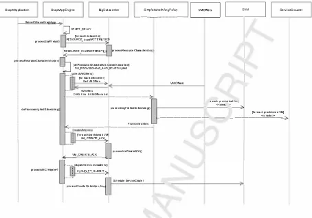
6.3. Scheduler and Execution of ServiceC!oudlet
[image:9.595.102.557.84.474.2]GraphApplicalion GraphAppEngine BigDatacenler
�-Smi_pl_•S_,_h•-du-li n
-gP-olc-i
y
-�
B
?
ServiceCloudletSubmit SlreamGraphApp 7
JsTART_DELAY
(for each datacenter)
processStar1DelayO RESOURCE_CHARACTERIST;s
RESOURCE CHARACTERISTIC processResourceCharacteristics
"" -
I
processResourceCharacterlslics(ev)
°J (ellRasourceCharecter1stlcsevenls recelved) DO_PROVISJONING_AND_SCHEDULING colleclVMOlf"ersQ
--[for each dalacenter]
Get VMOlf"ers � VMOffers
r
l
l
doProVisioningAndScheduling
VMO!rers
,__o_AG_F_ile_&VM_Olf_"_"'-"---;:a,
�
�reechprovlsloned\ti.,J
I
processD1gf1leAndSched ulmgO
f---�
_
·�---,;>
[for each provisioned VM] <<create>>
ProvislonedVMs
l<E---[fore.achprovtslonedVM]
VM_CREATE_ACK
3>
[] processVmCrealeACKO E<--VM __ c_REATE _ __ ,_c• _ __,_
[)
---di,patchS,NicoClou<li,tsQ
processVMCreate(ev) : CLOUDLET SUBMIT '
-7
�:�:ucooudiotSobmrt(ov. ""{
Schedule ServlceCloulel
Figure 4: Sequence Diagram: The flow of communication for init. lising loTSim-Stream and scheduling ServiceCloudlet on SVMs
initializing and what is the provisioning and schedulin" nolicy being used to schedule stream graph application on · /lultic" •id environment Algorithm I shows the pseudo-coo ... "f sim le provisioning and scheduling algorithm that Wf imole1 •. · ,ted
in IoTSim-Stream. This algorithm provisior thr mo�· suit able VMs for services included in stream 1ra1-· apr .1cation which meet the user perfo1mance requirer �nts for L.JOSe ser vices, where all VMs for a service are : ;ov1:,. -.,ed from one Cloud-based datacentre. For each sen' it finds VMs with higher computing powers upto require . MIi S value (that is cal culated based on user performance requ,. · ,1ent and service pro cessing requirement) and provisio .s tli�m tt .. achieve as much as possible from this value. The it' deb Lo VMs with lower computing powers to achieve the rcL "ir ng value. Neverthe less, in case of the selected ' J\1s lis' for any service is empty, IoTSim-Stream shows a mest ,ge to th user indicating that, and then is terminated. This h::m�e, .. i..� .. duse there is no VM offer
available in the selected ,atacen ·e that can achieve the required MIPS for processing at ·�ast on< stream unit according to the value of data processing fe,,,_ :.c:ment of such service. There
fore, the user in tha. ca:,, , .. either reduce the value of min imum stream unit (!eat.· ,g to reduction in the value of required MIPS for processing one tream unit) or add VM offer that sat isfies processing at least one stream unit for this service.
Figure 4 presents the flow of communication for ini tialising IoTSim-Stream, provisioning SYMs and schedul
ing ServiceCloudlet on the provisioned SVMs. Once
a stream graph application is submitted, GraphAppEngine handles this submission and sends to itself STARLDELAY event to allow enough time for BigDatacenters to initial ize. During processing this event, GraphAppEngine sends
RESOURCE_CHARACTERISTICS event to each BigData
center and waiting for their replies. When all BigDatacen ters send their replies as RESOURCE_CHARACTERISTlCS events, GraphAppEngine processes them and then triggers the process of provisioning and scheduling such application by sending to itself DO_PROVISIONI G_A. D_SCHEDULING event. In doProvisioningAndScheduling() procedure, the fol lowing functions are performed:
1. call collectVMOffers() procedure to collect all VM offers provided by BigDatacenters by querying them.
2. send XML file of submitted application along with the list of VM offers to scheduling policy. This policy then executes processDagFileAndScheduling() procedure to parse this file, extracts the structure of application, se lects the best suitable SVMs and prepares the scheduling plan. After the selection of suitable VMs, the objects for SVM and ServiceCloudlet are created.
3. retrieve the generated scheduling plan or table.
[image:10.595.73.527.84.402.2]0
I
�-E��I
[= __ .... _ ..
__,
I
�aI I
SVMI I
s�,�-I I
�emal�ce
I
I
St,urnS<he«JlingOnSVMs�ENO_OF _SIMJLATION
f"l.=.E>'�
STREAM IaartEX�ceSt,nms()
I �
I
I
---·
loop
END_OF _SIMJL, 'ON eve,.· "'Ot, �I
r-�
processEXSot,ceStream(ev) LJ
i ""qE,IN .!/lu� "'1.E <E--· ____ ,
p<ocessSt,nmAva,table(ev) �
COO�� -
--(
updateCloud@tProcessing()
lforeachhost) �leVmsProcessing(tlme) ;)
Add stream portion
(fo,eachVMJ
updateVmProcessing(time. nips) )i updateVmProcessing(lime, nips)
� each stream portion in 11'1)Ut0oeue)
[for each=�"ir:4 ::��;?<Mue]
(for each stream in vm.OUp..t()uNe) ( Add outDU Jtream
___ 9' "4:reamPc,.tlons&OestOatacenterAndVM(stream)
addStreamTrusmission(stream, srcDSid, srcVMid. des0Sid, desVMid. cohosted)
p,ocesslraMferStream(ev)
UPOATE_NETWORK
!for eaetl 11rive<f stream) STRENA_AVAILABLE
p<ocessSt,eomAveHoble(ev)
Q
Md St,eam� VM_Oota,.,.e,_Eveni
I
)
I
STOP SENDING STREAMI
change status of SeMceOoudlet to SUCCESSl
IYOC�'l.!iE°ndOfSiffllDtioni'\ I I VM-��UilJ
1---[ J
proc:essVMOeslroy(ev, ftalse)<<de5troy>> _____ 3,:i
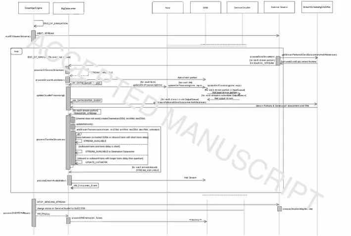
Figure 5: Sequence Diagram: Transferring and exchanging data streams among SVMs
proc:essSendStream(ev) (tor eaeh stream portion) EXSOURCE_STREAM
StreamPortions&DestOataceriersAndVMs(stteam)
---':),
e.4ftions&OestOatacenle,sAndVms
&ream Portions & Oestinalion dalacenlefS and VMs
I I
[image:11.842.77.786.48.524.2]Algorithm 1 Simple Provisioning and Scheduling Policy Require: minDPUnit a data processing rate for minimum stream unit in an application
I: for each service in Services do
2: selectedVMs <- ,P
3: requiredMIPS t-service.userreq * service.dataprocessingreq 4: p/aceme111Cloud <- pick random Cloud from avaliable Clouds 5: VMO.ffers t-- get VMJ/avours in accending orderofpmver
6: for each vm; in VMOffers do
7: vmMIPS +- get vm, power
8: if vmM /PS /service.dataprocessingreq < minDPU11i1 then
9: continue
IO: end if
11: if vmM I PS :-; requiredM I PS then
12: if i + I < 11 then
13: nextvmMIPS t- get vmi+I power
14: if nextvmMIPS > requiredM/PS then
15: toProvisionVM t- true
16: end if
17: else
18: se/ectedVMs <- selectedVMs U vm;
19: requiredM/PS <- requiredM/PS -vm; power
20: i <-i - I
21: end if
22: else
23: if i - I 2c O then
24: previousVmMIPS <- get vm,_, power 25: if previousVmM/PS 2c requiredM/PS && 26: previousVmM/PS < vmM/PS &&
27: previousVmMI PS /service.dataprocessingreq � minDPUnil then
28: i<-i-2
29: else
30: toProvisionVM t- true
31: end if
32: else
33: 10Pn1visionVM t- true
34: end if
35: end if
36: if toProvisionVM == true then
37: selectedVMs t- selectedVMs U vm;
38: requiredMIPS <- requiredMIPS -vm; power
39: 1(1Pmvi.1·ionVM <-false
40: end if
41: if requiredMIPS :<, 0 then
42: break
43: end if
44: end for
45: if .,·electedVMs is empty then
46: show message 'provisioning failed' lo the user
47: terminate the currently running simulator (i.e exit)
48: end if 49: end for
While rece1v111g acknowler' '- �inents (i.e.
VM_CREATE_ACK events) for SYM crt-..ttions : "ill BigData
centtres, each acknowledgement for or,� '1M is processed as
it arrives and the corresponding Serv· -.:eCJ udlet is dispatched
to this SYM by calling dispatchService-._· "Udlets() procedure;
this procedure sends CLOUDLEr _Sl''JMl1 event to corres
ponding BigDatacenter, which , -'), .sse� the received event
(CLOUDLELSUBMIT) and c�Jiech,_ ·c chis ServiceC!oudlet
on a SYM.
Figure 5 shows the proces� ')f send' 1g data streams from ex ternal sources and transf" '.ng , .. ,,..c and output data streams to and from SVMs. Or ;e a s1:rL ,m graph application is being scheduled on SYMs (i.e. Servic ;Cloudlets of application ser vices have been sch rlnled u11 .) YMs and ready for execution), the GraphAppEnginc ser 1:,, ,J itself END_OF _SIMULATIO
event with the delay SJ:. cified by user-defined requested sim ulation time; this even, will being sent after this delay, which triggers the end of simulation process. Then, it sends SEND_STREAM events to all external sources requesting them to start sending their data streams to corresponding BigData centers, where these datacentres will forward those streams to
respective SYMs. At that time, the simulation begins.
Each external source that receives SEND_STREAM event will process it and queries Strear�SchedulingOnSVMs object about the portions of its streaIT <tnd the information of Big Datacenters and SYMs where .hest , "ttions should be trans ferred and available. When ·: .. ·e portions are received along with the relevant informa' on ( .e. destination BigDatacen ters and SYMs), this externa. rrnrce immediately sends them as EXSOURCE_STREA!v, ·,,entl> to destination BigDatacen ters. Each EXSOUP _,_ STI-<.LAM event will be processed by corresponding , 1gDr .act. .. ,er whose will send to itself STREAM_AVAILABL_- event. It then processes this event to make stream po-.1011 availhule in the corresponding SYM by
adding such p01 ion to u ! input queue of corresponding SVM
and sends to itseJ. "M r ,ATACENTER.EVE T.
When Vf d>A,.,.,"CE TER.EVENT being received by Big
Datacenter, it _,wee ses this event and then updates the state
of all Si. ··,later' r .,tities in a BigDatacenter. At this point,
all stream pv. :ons available in input queues of all SYMs in
all hv, ·" will 1 e moved to the input queues of correspond
ing � ·•·vict..::::,rndlets via their schedulers, making them avail able for , . "Cessing. As well, all output streams available in
0 ... "�ut queues of ServiceC!oudlets as results of computations
will bt. ,oved to output queues of corresponding SVMs in or cte• '" Je transferred later. ext, this BigDatacenter sends an
L -1er VM_DATACE TER.EVENT to itself for future updat
in5 After that BigDatacenter starts the next communication fluw to transfer output streams of ServiceC!oudlets available at .heir SYMs to destination SYMs in order to be input streams for others ServiceCloudlets. Thus, BigDatacenter checks out put queues of all hosted SY Ms looking for any output stream available as a result of completed computation. For each output stream available at a SYM, it queries StreamSchedulingOnS YMs object about the portions of such stream and the informa tion of destination BigDatacenters and SVMs where these por tions should be available. It then use this information to send each stream portion to destination BigDatacenter as a message (i.e. TRANSFER_STREAM event) via event mechanism.
Each TRA SFER_STREAM event is processed by corres
BigDatacen-ter updates the processing of stream transmissions in all ingress and egress channels, where for each arrived stream, it sends STREAM_AVAILABLE event with ingress or egress latency based on transmission type to corresponding destination Big Datacenter (i.e. itself or other BigDatacenter). Such Bigdata center will process this event to make the transferred stream portion available into the corresponding SYM.
Nevertheless, the whole process of transferring and exchan ging streams among different SYMs hosted in different Big Datacenters continues until END_OF _SIMULATION event be ing received (i.e. thereafter the pre-defined delay at the begin of simulation). At that time, GraphAppEngine receives this event and processes it, and then starts the end of simulation process, which includes the followings:
I. stop external sources from sending their streams
to corresponding BigDatacenters by sending
STQP _SENDING_STREAM events to them.
2. change the status of all ServiceCloudlets to 'Success', in dicating the end of their executions.
3. destroy all provisioned SVMs by sending VM_Destroy events to their BigDatacenters, which process these events and destroy the hosted SY Ms.
When dealing with scheduling, CloudSim has two sched ulers, which are VmScheduler and CloudletScheduler. n YmScheduler is host-level scheduler that can run either in space-shared or time-shared mode for allocating cores of '"·n cessor from a host to YMs (i.e. virtual machine monitor , '· location policy). While, the CloudletScheduler is VM-level
scheduler that can also run in one of the aforementior -u •. "'des
for determining the computing power share betwef 1 Cloud! ts in a YM [3]. Since each ServiceC!oudlet is sub•nith .. ' •o ne SVM and this SVM needs to handle the contir .1ou� ;!XecLttion of this cloudlet to process incoming streams ar,_ ...,rr Juct' Jutput
stream, the new YM-level scheduler is requ; ed. 'l , .. -, .ore, we
implement YM-level scheduler named St> ,: · CloudletSched
uler for each SYM within IoTSim-Stream. This �, ··eduler runs in space-shared scheduling mode.
As the ServiceC!oudletScheduler i .. ··un- mg, it continuously checks its input queue (inputQuer ;) 100._ ·.,g for any incom ing streams. If inputQueue is ,ot r ,nptv and the waiting StreamsForNextPC flag is true (se._' · .1e 3- J, the ServiceCloud letScheduler enters into the v :.::e-1001- 111d performs the fol lowing steps on each iteratio (see L1. e 39 - 57):
I. Fetches the head of ;,.,pu,.:::_--- .c (i.e. input stream por tion with least port' Jl1 id) r. d dequeues this stream in case of this stream is nL · existin , in working input stream list (workfinglnputStrean,,, ... ,d then adding it into such list, preparing for n, 'tr, ,. e Line 42 - 46).
2. Checks if all requ1. 'd stream portions for one PC arrive and they are added to workfinglnputStream in order to per form the appropriate action (see Line 47 - 56):
• If yes, it then checks if the time required to process streams included in this PC based on the capacity
12
of cloudlet is less than 0.1, therefore it moves those streams to assumeProcessedStreams list and empties
workfinglnputStream Ii ·t. Otherwise, it changes the
flag of "check" to fa!� This flag helps to get out of
while-loop either in ,ase 0: -tream portions included
in workfinglnputS· _ '11 list need processing time at
least as long as '.1e rr nimum time for one PC (i.e. 0.1) or the head 01 : ()UtQueue is stream portion for next PC based o, .. '01ti0.1 id.
• If no, it ch, .1ge: the "check" flag to false if the value of contiff °Ch c:k hag is false. The continueCheck flag is n�ed ,. <:ontinue in while-loop as the pre vious .1ead or inputQueue has been dequeued from this ct 1eue (se Line 42 - 46), so that in next iter
ati0"', ti,. --- .c head can be fetched and checked to t � eit�,. iequeued or not. That is very important to 1, · ., and dequeue all of those streams required for
.,e r .= dS they arrive and before the next update of
the '- ·heduler if possible, ensuring low-latency data
oror ,ssing.
When� '1 required stream portions for one PC arrive and they
a.· 'ldded to workfinglnputStream, and waitingStreamsForNex tPC t1< is true, the scheduler calculates the total size of input SL1• � ... portions and using it with the value of data processing . · -1uirement for a service to update the length of cloudlet. Then, it L ·.anges the startPC flag to true that indicates the start of one
h .. .: and waitingStreamsForNextPC flag to false as we are in the ,ihase of starting the execution of one PC (see Line 60 - 70). After that, the scheduler starts the execution of this PC to pro cess the included stream portions in such PC and updates com pletion/progress accordingly (see Line IO - 13). While the ex ecution of one PC and updating its progress, the scheduler also checks the completion of this PC, so that when the execution finishes (i.e. renaming cloudlet length equals zero), it performs the following steps (see Line 15 - 35):
I. changes the startPC flag to false that indicates the end of execution of one PC (this PC).
2. produces the output stream and add this stream into out putQueue.
3. empties the working stream list (workfinglnputStream) 4. changes the waitingStreamsFor extPC flag to true that in
dicates the current status backs to wait for stream portions to be arrived if they are not arrived yet and to fetch those portions from input queue required to start new PC.
7. Validation and Evaluation
Algorithm 2 ServiceCioudletScheduler for scheduling and ex
ecuting ServiceCloudlet on a YM
I: outputQueue t-- </J
2: inputQueue t-- </J I> PriorityQueue sorting stream portions by ids - ascending order 3: workinglnplllS /reams<-¢ • list of input streams for a Processing Cycle (PC) 4: as.mmeProcessedS /reams t-- cp c- list of input streams that is assumed to be processed
5: .\"lar1PC <-false • flag for starting one PC
6: waitingStreamsForNextPC t-- true
7: 101al0111pwSize <- 0
8: 1o1al/np111Size <- 0
9: for each ServiceCloudlet cl in CloudletExecList do • One ServiceCloudelt exists I 0: if startPC == true then • when all required input stream portions are available
for one PC
start pmcessing stream portions in this cycle update the completion of this cycle
end if II: 12: 13: 14:
15: if waitingStreamsForNextPC == false then • Execution of one PC for
ServiceCloudlet is in progress
16: if rcl.getRemainingCloudletLength() == 0 then • Completion of one PC 17: .11ar1PC <-fafae
18: produce output .\'lream 19: if totaOutpuLSize == 0 then
20: lotaOutputS ize t- size of output stream
21: end if
22: if totallnputSize == 0 then
23: totallnputS ize +- sum sizes of required input streams
24: end if
25: 11111110f ProcessedS1rea111s
size ofworkinglnputStreams + size ofsassumeProcessedStreams size
<-26: processedPortion.\'S ize .._ max portion size * mun.OfPrr)(;essedStreams
27: proportionlnToOut .._ totalOutputS ize/totallnpulS ize
28: outputs treamS ize .._ proces.\·edPortionsS ize * proportionlnToOut
29: create output .\'/ream with outputStreamSize
30: enqueue created output stream in outpwQueue
31: workinglnpwS /reams<-,p
32: assumeProcessedS I reams.._ <P
33: waitingStreamsForNextPC .._ true 34: end if
35: end if
36: 37: 38: 39: 40: 41:
if inputQueue is not empty && waitingStreamsForNextPC == true then
check .._ I rue
while check && input Queue is not empty do
continueCheck .._ false
stream_portion .._ retrieve the head stream por1ion ofth , queue
dequeue from priority queue
42: if stream_portion is not in workinglnputStreams then
43: strean1-portion .._ perofrm dequeue operation/ JIil int ,!Queue
44: add stream_portion in workinglnputStreams
45: continueCheck .._ true
46: end if
if stream portions required for one PC being ·=ved then
t> 101
47:
48: if required MIPS for processing these .rrea... 'o this PC/ cloudlet
capacity i 0.1 then • 0.1 is n,. Lime for one PC
49: move stream portions to as.rnmer .,� -,·edStream.\· list
50: workinglnputS treams .._ <P
51: else
52: check <-false
53: end if
54: else if continueCheck == false' .en 55: check<- false
56: end if
57: end while
58: end if
59:
60: if stream portions required for on. °C beinp .rrived && waitingStreamsForNex
tPC == true then
61: lnPortion.\'Size .._ sw .-;izes ofi '1Ul .\'treamportion.-;
62: cllength .._ service_, ·ocessing_r, , * lnPortionsS ize
ServiceCloudlet • length of
63: if cloudlet length== I t.. • value assigned when cloudlet initialised
64: cl.lenglh = I ..• .,, 101a/ lengll1 ofServiceClo11dlel + clLe11gll1)/cpus)-l • length in MIPS
65: else
66: cl.le11g1h = (curre, 101a/ /e11g1h ofServiceCL011dle1 + c/Leng1h)/cp11s length in MIPS
67: end if
68: star/PC<- /r11e
69: wai1ingS1rea111sForNex1PC <-false
70: end if
71: end for
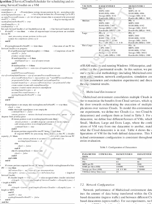
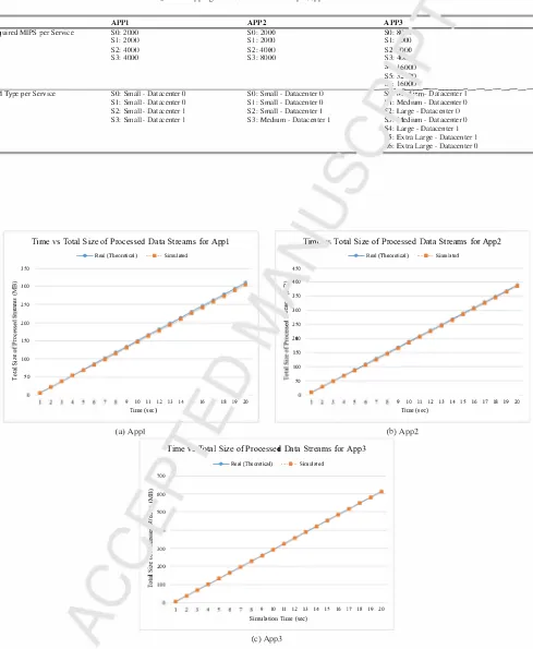
Table 4: Types and Configuration of VMs in Modelled Datacenters
VM TYPE Small
Medium
DATACENTER O DATACENTER l
PEs: 2 PEs: 2 MIPS: 1000 MIPS: 20(Xl
RAM (MB): 4096 RAM (MB): 4096
Storage (MB): 8192 �•orage (MB): 8192
Bandwidth (MB/s)· -� --�B�a�n_d�wid_L_h_�(M_B�/s�):_I ()( _)_O __
PEs: 4 PEs: 4
MIPS: J(J(){J MIPS: 2000
RAM (MB): 7168 RAM (MB): 8192 Storage (MB,. "'184 Storage (MB): 18432
Bandwidth (MB/s,. "'lO Bandwidth (MB/s): )()() 0
---,La�r-ge---�P�E-s:"'8,,..--- --- ---,P�E"'s-: "'8-�-�---MIPS: . JOO MIPS: 2000
RAM, 'Fl): -'336 RAM (MB): 16384
Storage (th · 32768 Storage (MB): 34816 ---,a---��---�B? Extra Large r
_,s:rr-
:dth (M'--. ': J()(Xl Bandwidth (MB/s): PEs: 16 10001 'IPS: 1000 MIPS: 2000 R. "1 (MB)· 0720 RAM (MB): 32768
Stora0• , . ..s): 65536 Storage (MB): 69632
B•· . ·•idth (MB/s): 1000 Bandwidth (MB/s): 1000
of RAM men,. --y and running Windows IO Enterprise, and then colleL· �q: thee ;perimental results. In this section, we present
our'-·rient,._ .. Lal methodology (including Multicloud environ ment co1, .' �uration, network configuration, simulation config
Lt .. •ion parameters and evaluation experiments) and discusses
the exi-, --imental results.
Multicloud Environment
M.ulticloud environment consolidates multiple Clouds in or ier to maximize the benefits from Cloud services, which opens the door towards orchestrating the execution of multiple ap plications over various Clouds. To model this environment for our experiments, we define two Clouds (i.e. two Cloud-based datacentres) and configure them as listed in Table 3. For each datacentre, we define four different flavours of YMs, which are Small, Medium, Large and Extra Large, where the configur ations of VM vary from one datacentre to another, matching what the Cloud datacentre is in real. Table 4 shows the con figurations of YM for the both defined datacentres. This Mul ticloud environment configuration is consistent throughout the entire evaluation.
Table 3: Configuration of Datacenters
PARAMETER
CONFlGURA-TlON
Hosts PEs
MIPS per PE
RAM per Host (MB)
Storage per Host (MB)
VM Boot Delay Time (sec)
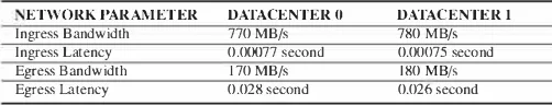
7.2. Network Configuration
DATACENTER 0
1000 64 )()(){) 144000 14(J()(X)O 20 DATACENTER l 1000 64 2000 176000 1500000 20
[image:14.595.45.542.88.756.2] [image:14.595.307.558.586.658.2]