City, University of London Institutional Repository
Citation
:
Rahman, B. M., Uthman, M., Quadir, A., Grattan, K. T. V., Markides, C. &
Themistos, C. (2015). Emergence of THz technologies and design and optimisation low-loss
waveguides and devices. In: Electrical and Computer Engineering (ICECE), 2014
International Conference on. (pp. 389-393). IEEE. ISBN 9781479941667
This is the accepted version of the paper.
This version of the publication may differ from the final published
version.
Permanent repository link:
http://openaccess.city.ac.uk/14525/
Link to published version
:
http://dx.doi.org/10.1109/ICECE.2014.7026819
Copyright and reuse:
City Research Online aims to make research
outputs of City, University of London available to a wider audience.
Copyright and Moral Rights remain with the author(s) and/or copyright
holders. URLs from City Research Online may be freely distributed and
linked to.
City Research Online:
http://openaccess.city.ac.uk/
[email protected]
Emergence of THz Technologies and Design and
Optimisation Low-loss Waveguides and Devices
B.M.A. Rahman,
1,*M. Uthman
1, A. Quadir
1, K. T. V. Grattan
1, C. Markides
2and C. Themistos
2Dept. of Electrical and Electronic Engineering, City University, London, UK
School of Engineering and Applied Sciences Frederick University, Nicosia, Cyprus
Abstract— THz is an emerging technology with many important applications in imaging and sensing, but due to lack of suitable low-loss waveguides future progress can be limited. A rigorous full-vectorial modal solution approach based on the computationally efficient finite element method is used to find the propagation properties of THz waveguides. Design approaches are presented to reduce the modal loss of such waveguides. Designs of several THz devices, including quantum cascade lasers, power splitters and narrow-band filters are also presented.
Index Terms—Finite Element Method, Terahertz Waveguides, THz Devices.
I. INTRODUCTION
The emerging terahertz (THz) region occupies a large portion of the electromagnetic spectrum, located between the microwave and optical frequencies and normally is defined as the band ranging from 0.1 to 10.0 THz. In recent years, this intermediate THz radiation band has attracted considerable interest, because it offers significant scientific and technological potential for applications in many fields, such as sensing [1], imaging [2] and spectroscopy [3]. However, waveguiding in this intermediate spectral region is a major challenge and strong dielectric and conductive losses in the terahertz frequency range have been a major problem for the development of practical low-loss waveguides. Due to the lack of suitable low-loss waveguides most of the present day THz systems uses free-spaces transmission. The availability of low-loss waveguides and followed up by THz guided-wave devices can improve the functionality and reliability of future THz systems. The conventional guiding structures exemplified by microstrips, coplanar striplines and coplanar waveguides are highly lossy and dispersive. However, so far the most promising dielectric waveguides have been the use of photonic crystal fibers at terahertz frequencies [4, 5] and metal coated guides [6] at terahertz frequencies. In this paper, various types of practical dielectric and metal coated waveguides are evaluated and design optimization of Quantum Cascade Lasers, MMI-based power splitters and narrow-band filters are presented, by using full-vectorial finite element method [7].
II. PAGE LAYOUT
Dielectric waveguides in silica, silicon, polymer, and other semiconductors materials have been widely used at optical frequencies due to their low-loss values: however most of these materials are very lossy at the lower terahertz frequency range and not so suitable to fabricate THz waveguides. Particularly, silica has been extensively used to fabricate a new class of optical fibre, the photonic crystal fibres (PCF),
however, as its material loss is prohibitively high at THz frequencies, only recently, Han et al. [4] have fabricated a PCF for THz using alternative high-density polyethylene (HDPE) with modal loss values of 0.2 cm-1 and Goto et al. [5] have reported a PCF-like waveguide using Teflon tubes and filaments with loss values of 0.5 cm-1, showing their potential. A typical PCF cross section with a triangular array of holes is shown in Fig. 1. The structure predominantly consists of such periodic air-holes with diameter, d, and the pitch length between the two nearest holes is Λ. In this work, a refractive index value ng = 1.444 is considered, at the operating frequency 1.2 THz (wavelength 0.25 mm). Variations of the effective indices for both the fundamental Hx
11 and the second Hx
21 modes for d/Λ = 0.9 are shown in Fig.2. It can be noted that for both the modes, the effective indices reduce monotonically as the pitch length is reduced. The variation of the nfsm value with the pitch length is also shown by a chained line for d/Λ = 0.9 at 1.0 THz. The nfsm represents a frequency dependent equivalent index of the perforated cladding region and this was calculated by solving a unit cell problem with periodic boundary conditions implemented around all the four sides. It can be observed that the effective index curve for the Hx21 mode crosses the nfsm line at a pitch length, Λc = 0.24 mm, so when the pitch length is reduced below 0.24 mm, the second mode cannot be guided anymore. On the other hand, the effective index for the fundamental, Hx
11 mode also crosses the nfsm line, but at Λc = 0.11 mm. So, a PCF with d/Λ = 0.9 and pitch length between 0.11 mm to 0.24 mm would be strictly single moded. By controlling the d/Λ ratio and the pitch length the modal properties of such low-loss PCFs at THz operating frequency can easily be controlled. It is possible to broaden the single mode operating region or even design an endlessly single mode PCF by reducing the d/Λ
[image:2.595.352.498.624.756.2]value.
Fig. 1. Cross section of a Photonic Crystal Fiber
Λ
The modal loss of a guided mode in a PCF is due to the combination of the material loss and the leakage loss. The leakage loss arises due to the modal index being lower than the surrounding high index cladding regions. For this study a PCF with parameter d/Λ=0.5 is used. To consider the effect of the loss tangent, three different values of the ni, (the imaginary part) have been considered. Additionally, Perfectly Matched Layers (PML) were added around the conventional waveguide boundaries to calculate the leakage losses. Figure 3 shows the loss mechanism in a PCF. In the absence of any material loss, for ni = 0, the leakage loss is shown by a solid line. It can be observed that as the pitch length is reduced, the leakage loss increases almost linearly from a very low loss value. It should be noted that Perfectly matched Layers (PML) region around orthodox computational boundary should be introduced to obtain leakage loss of any waveguide. In the case of ni = 0.00119, the total loss included both the leakage loss and the material loss, which is shown by a dashed line. At a higher pitch value, when the leakage loss is negligible, the total loss is mainly attributable to the material loss. However, it can be observed that modal loss is more than 100 dB/m, this is only because lack of suitable dielectric material in this frequency range.
d/Λ=0.9 f=1.0 THz
Λ mm
0.0 0.2 0.4 0.6 0.8 1.0 1.2 1.4 1.6
[image:3.595.331.526.295.441.2]ef fect ive i n d ex 1.0 1.1 1.2 1.3 1.4 1.5 Hx11 Hx21 nfsm
Fig. 2. Variation of the effective indices with the pitch length, Λ.
Pitch Λ (mm)
0.20 0.25 0.30 0.35 0.40 0.45 0.50
M o d al lo ss (d B /m ) 0.1 1 10 100 1000 C o nf in ement f act or ( % ) 75 80 85 90 95 100
ni=0.00119
ni=0.005
ni=0
d/Λ=0.5
[image:3.595.70.274.336.478.2]f=1.0 THz
Fig. 3. Material and leakage losses of PCF
Since at present the available dielectric materials at THz frequencies are considerable lossy, a novel design approach is considered next, where besides the porous cladding with air-holes, additionally a porous core PCF is considered. As the waveguides dimensions for THz frequency are considerable bigger than that for the optical wavelength, it would be relatively easy to fabricate such microstructured core. Two different d/Λ values are used for core (d/Λi) and cladding (d/Λo), and for cladding this value has to be smaller to have higher equivalent index in the core for wave guidance.
Variation of the power fraction in the air-region of the porous core is shown in Fig.4. As shown in this figure, the power confinement can be increased to 35% in the low-loss air-holes of the cores, and additionally another 25% in the cladding air-holes [8], but this is not shown here. So, in this design, the overall modal loss mainly arises due to the material loss of the polystyrene, and this can be reduced by 60% but using such perforated core besides air-holes in the cladding region. The overall reduction is significant, but still need more work to be done to make the more suitable for practical applications.
Amongst the various THz waveguides that have been suggested, the metal-clad waveguides supporting surface plasmon modes show the greatest promise as low-loss waveguides for use both in active components and as passive waveguides. Several waveguide structures incorporating metallic layers have been reported, such as low-loss and flexible hollow polycarbonate waveguide with copper and dielectric inner coatings, deposited by using a liquid chemistry approach [9].
d/Λi
0.3 0.4 0.5 0.6 0.7 0.8 0.9
Γ max ai r-c o re 10 15 20 25 30 35 40
d/Λo = 0.8
d/Λo = 0.9
d/Λo = 0.95
Λo = 0.35mm
Λo = 0.039mm
[image:3.595.357.512.485.637.2]Teflon λ = 0.3mm n = 1.445 ni = 0.00119
Fig. 4. Variation of power confinement in the porous air-holes in the core
region with the pitch length, Λ
Fig. 5. Metal-coated hollow glass waveguide
[image:3.595.68.278.508.651.2]the silver metal cladding layers and the silica ring are taken as np=1.58 –j0.0036, nm=308-j532 and ns=1.96 –j0.0061, respectively at an operating frequency of 2.5 THz. At this frequency, as the air is also not absolutely loss-free, to represent this loss factor its complex refractive index is taken as 1.0 - j 1.1x10⁻⁶.
Fig. 6. Attenuation constant with the polystyrene thickness, p, for t=0.4μm
There are two metal/dielectric interfaces, which can support surface plasmon modes (SPM), one the outer silver/silica boundary and the other at the inner silver/polystyrene (or air, when p = 0 μm) boundary. This waveguide supports two SPMs along these two metal/dielectric interfaces. The refractive indices of the inner and outer cladding materials being very different, the two SPMs have widely different propagation constants and they do not interact with each other. However, at the right and left hand sides of the metal/dielectric interfaces, when the same electric-wall boundary condition is imposed, the Hx field is forced to be zero at the metal boundary and no SPM exists. Another mode with the dominant Hy field, would form a similar SPM; however, at the left and the right interfaces. The Hy field profile of this mode is similar to the Hx field profile, but rotated by 90 degrees. These two modes have identical propagation constants and being degenerate, they can be superimposed to form radially polarized RP-like modes.
Fig. 7. Effective index and loss with Teflon thickness
for the Hx 10 mode
The loss values of the fundamental plasmonic mode increases with the PS thickness and not shown here, as this mode was more lossy. The attenuation characteristics of the RP02 mode, with the variation of the polystyrene thickness, for
a silver thickness t = 0.4 μm, is shown in Fig. 6, where the loss contribution of the polystyrene and silver layers has also been examined. As can be seen from the above characteristics, the total attenuation shows a maximum and a minimum loss at a polystyrene thickness of about 1 μm and 13 μm, respectively. The attenuation curves due to the polystyrene and the silver layer exhibit similar trend with the total attenuation. Throughout the range of polystyrene thicknesses examined, the optical power confinement in the inner air-core is of the order of 99.9%, thus contributing a constant attenuation of about 0.25 dB/m. For a polystyrene thickness lower than 5 μm, the total attenuation is affected mainly due to the metal attenuation but as the polystyrene thickness increases above 5
[image:4.595.323.531.315.464.2]μm the total attenuation is mainly governed by the loss in the polystyrene layer. This mode shows a greater promise to achieve low-loss guidance through a metal clad dielectric waveguides. It would also be easier to couple this mode since the field profile is also very close to a Gaussian shape [10]. The modal loss of this waveguide, when design is optimized, is significantly lower than most of the THz waveguides reported so far, as most of the power is being guided in the central air-hole region.
Fig. 8. Field profile of Ey mode in a THz Quantum Cascade Laser. The field
inside the confinement layers is shown on the inset.
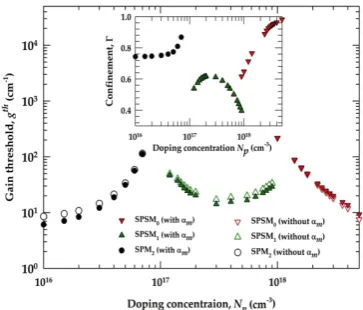
Fig. 9. Gain threshold of several plasmonic modes.
[image:4.595.338.520.522.677.2] [image:4.595.42.285.551.721.2]dielectric-clad metal-coated waveguide can also be less lossy. A thin metal coating would support plasmonic modes, but these are relatively lossy. However, a Teflon coating on the gold layer can draws field away from the lossy conducting layer and loss may reduce considerably. Figure 7 shows the variation of the loss value with the Teflon thickness for the Hx
12 mode in an air-core 1 mm x 0.6 mm rectangular waveguide with 0.7 μm gold coating at 2.5 THz. It can be seen that at the optimum 21
[image:5.595.338.522.104.246.2]μm Teflon thickness, the loss value can be 3.5 dB/m, one of the lowest reported so far [11]. The evolution of third order mode for no Teflon coating to a near Gaussian profile for 18 µm Teflon coating are shown as insets. In this guide also, the fundamental TE10 or TE01 mode was more lossy and its loss value rather increased with the polystyrene coating. Further improvement in the waveguide design to reduce loss and dispersion can encourage the development of THz guided-wave systems.
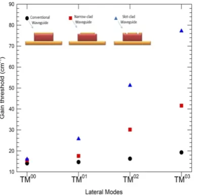
Fig. 10.Gain Threshold of the lower order modes for different waveguides
We also need good sources for THz generations. There are some convergences for the development THz sources from microwave engineering to increase the frequency and from photonics to reduce the frequency. Quantum cascading lasers [12] are emerging as efficient high power THz source for many important applications, such as imaging and sensing. However, for the THz frequency, it is not possible to grow the semiconductor materials comparable to the operating wavelength. For this reason, for THz QCL often smaller height needs to be considered and plasmonic confinement is used in that direction. The plasmonic confinement in the vertical direction is shown in Fig.8, which clearly shows the mode formation at the metal-dielectric interfaces. However, it is easily possible to have a wider guide, so mostly dielectric confinement is used in horizontal direction. The gain threshold for such QCL is shown in Fig.9. Because of the wider guides, the gain threshold difference between the fundamental and higher order (lateral) modes are very small. This allows possibility of mode hopping for any external changes. A novel design approach is considered [13] using slotted upper metal clad, to enhance the gain threshold of the higher order modes. Figure 10 clearly shows that gain threshold of the higher order modes are increased for slotted-electrode designs. This would reduce mode competition and the resulting output beam would be more stable with the environmental variations. Besides reducing waveguide loss of
[image:5.595.72.267.263.455.2]QCL, it may also be possible to increase the operating temperature of QCL, another critical issue in the further development of room-temperature QCLs.
Fig. 11.FDTD Simulation of the MMI 3dB coupler
For the future THz system, it is essential to design various integrated guided-wave components. In that spirit, it is shown here that a compact power splitter can be designed by using the MMI principle. In Fig. 11, it is shown here that an efficient power splitter can be designed by using a 35 μm long multimoded section [14]. A Finite Difference Time Domain (FDTD) approach is used here to simulate this structure.
Next, a Terahertz frequency range band-stop filter for molecular sensing [15], where two 5 μm wide band-stop filter stubs with a length of 192 μm and 83 μm are placed at a 400
μm apart along the direction of propagation, as shown in the right inset of Fig.12, has been considered. The structure of the microstrip is also shown as an inset on the lower left side. Initially the above device has been simulated without a polysterene film on top of the metal layer, using the FDTD approach and the variation of the insertion loss with the frequency is presented in Fig.12. As can be seen from the above frequency response, the device exhibits two resonant frequencies due to the stubs at about 600 and 800 GHz, with a minimum insertion loss of about -55 and -30 dB. These resonant peaks will shift due to presence of any external materials on the microstrip and measuring this frequency shift, a THz sensor can be developed.
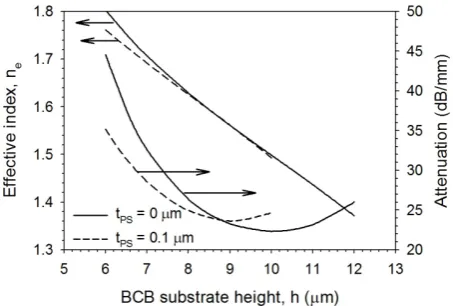
[image:5.595.326.529.557.710.2]Fig. 13.Variation of the effective index and attenuation with BCB substrate height of the microstrip line.
Finally, the BCB substrate height, h, has then been varied and the effective index and attenuation of the microstrip structure with no polysterene layer on top of the metal and that with a 0.1 μm film thickness of the above material have been examined and presented in Fig.13. As can be seen from the above characteristics, as the substrate height increases both the effective index and the attenuation decrease, with the corresponding values of the structure with the polysterene film being lower than those obtained for the device without it. At a substrate height of about 9 μm, the above corresponding values are about the same for both the structures examined. However, the device with the polysterene film exhibits minimum attenuation at the above substrate height and as the substrate height increases further the attenuation of the structure with the polysterene layer becomes higher than that obtained for the structure without the above material.
III.CONCLUSIONS
A finite-element approach, based on a full-vectorial H-field formulation, has been used to study the detailed modal properties of dielectric and metal clad waveguides operating in the THz frequency range. It is also shown here that by using porous core the effect of material loss can be reduced significantly. It is also shown by using a thin but optimized dielectric over-layer plasmonic loss in a hollow-core waveguide can also be reduced. It is also shown here that by using a novel slot-type electrode, the differential loss of the higher order modes can be significantly increased to reduce mode hopping. Finally, simple guided-wave devices such as power splitters and band-pass filters are also presented here. The full-vectorial numerically efficient finite element based design approach used here can be extended to optimize not only THz waveguides but also more advanced guided-wave devices for future THz integrated circuits (TIC).
REFERENCES
[1] R. H. Jacobsen, et al., “Chemical recognition of gases and gas mixtures
with terahertz waves,” Optics Lett., 21, no.24, pp. 2011-2013, 1996.
[2] Q. Chen, et al., “Near-field terahertz imaging with a dynamic aperture,”
Optics Lett., 25, no.15, pp.1122-1124, 2000.
[3] J. Q. Zhang and D. Grischkowsky, “Waveguide terahertz time-domain
spectroscopy of nanometer water layers,” Optics Lett., 29, no.14,
pp.1617-1619, 2004.
[4] H. Han, H. Park, M. Cho, and J. Kim, “Terahertz pulse propagation in
plastic photonic crystal fiber,” Appl.Phys. Lett, 80, no.15,
pp.2634-2636, 2002.
[5] M. Goto, et al., “Teflon photonic crystal fiber as terahertz waveguide,”
Jpn. J. Appl. Phys, Part 2 43, L317-L319, 2004.
[6] R. W. McGowan, et al., “Propagation of ultrawideband short pulses of
Terahertz radiation through submillimeter diameter circular waveguides,” Opt. Lett, vol. 24, no. 20, pp. 1431-1435, Oct 1999.
[7] B. M. A. Rahman and J. B. Davies, “Finite-element analysis of optical
and microwave waveguide problems,” IEEETrans. Microwave Theory
Tech, MTT-32, no.1, pp.20-28, 1984.
[8] M Uthman et al., Design and characterization of low-loss porous-core
photonic crystal fiber, IEEE Photonics J, vol. 4, no. 6, pp.2314-2325, Dec 2012.
[9] J. A. Harrington, et al., “Hollow polycarbonate waveguides with inner
Cu coatings for delivery of terahertz radiation,” Opt Express, vol. 12,
no.21, pp. 5263-5268, Oct. 2004.
[10] C. Themistos, et al., “Characterization of Silver/Polystyrene (PS)-coated
hollow glass waveguides at terahertz frequency,” J. Lightwave.
Technol., vol. 25, pp. 2456-2461, no. 9, September 2007.
[11] B.M.A. Rahman, A. Quadir, H. Tanvir and K.T.V. Grattan,
“Characterization of Plasmonic Modes in a Low-Loss Dielectric-Coated
Hollow Core Rectangular Waveguide at Terahertz Frequency,” IEEE
Photonics Journal, vol.3, pp.1054-1066, 2011.
[12] J. Faist, et al., “Quantum cascade laser,” Science, vol.264, pp. 553-556, 1994.
[13] H. Tanvir, B.M.A. Rahman and K.T.V. Grattan, “Impact of “Ghost”
Mode Interaction in Terahertz Quantum Cascade Lasers,” IEEE
Photonics Journal, vol.3, pp.926-935, 2011
[14] C. Markides, et al., “Multimode Interference 3dB splitters in hollow
core metallic waveguides for low loss THz wave transmission”, IEEE J.
Selected Topics in Quantum Electron. Vol. 19, ID 8500606, Jan. 2013.
[15] J. Cunningham, C. Wood, A. G. Davies, I. Hunter, E. H. Linfield, and