AFRC’s Image Processing Platform: A
High Speed User-Friendly Architecture for
Real Time Object Detection in Forging
Processes
Danial KAHANIa,1, Remi ZANTEa
aAdvanced Forming Research Centre (AFRC), University of Strathclyde, 85 Inchinnan Drive, Inchinnan, Renfrewshire, PA4 9LJ, Glasgow, UK
Abstract. Real-time detection and measurements of hot parts is desirable to permit real-time process control and automated part handling in harsh environments like forging and forming. The image processing platform described provides improved performance of Graphical User Interface (GUI), fast processing speed and integrity over industrial packages which are typically used in process control of forging processes or harsh manufacturing environments. A flexible, image processing software package for detecting objects in manufacturing environments has been developed at the Advanced Forming Research Centre (AFRC). The software consists of a set of image processing tools, written in MFC/C++ and OpenCV for Windows platforms. The software provides a powerful flowchart-based GUI for designing image processing algorithms. AFRC’s Image Processing Platform can be easily integrated with other industrial software packages like GE Proficy® using ActiveX technology. The package was successfully tested for real-time hot object detection inside a hot furnace in a forging environment.
Keywords. Forging, Image processing, Robot vision, C++.
1. Introduction
Forging is a manufacturing process which shapes hot metal using localized compressive external forces. The forging industry is a key link between manufacturing suppliers and end user industries. Forging is a cost effective way to produce components that are close to the finished size and shape, requiring a minimal amount of finishing processes. Forging products range in size from less than 50 grams to more than 150 tons and are found in various sectors covering many applications. Forged products are essential to the industrial economy, society, and national security [1]. Forging factories are particularly harsh environments for operators and can be difficult and uncomfortable places to work due to ambient noise and heat, weight of parts and danger in operating fast moving presses or hammers to deform sizable pieces of hot metal [2].
Production methods in manufacturing industries have undergone major changes through the introduction of digital computers resulting in increased competitiveness for companies involved in these industries. The forging industry has to make significant
technological improvements to accommodate shorter production times with better part quality [3]. One of the specific areas in which technological issues need to be addressed includes process control and monitoring. In order to meet the competitive challenges of the future, the forging industry must fortify itself in several critical areas like automation and technology development [4].
Advanced control systems permit forgers to produce products with better quality, to meet customers' stringent delivery schedules by maintaining and increasing throughput and also provide a working environment which is safer. Advanced process control systems and sensors should monitor the entire forging process so that each operation will automatically sense and compensate for process variations in other operations. This requires designing and implementing a smart, stable and flexible automation process to improve utilization of energy, raw materials, and labour [4] [5].
Success in the automation of forging processes is clearly linked with the development of advanced robotic systems. Using robotic technology it will be possible to control the position of the part accurately and also synchronize it with the relevant handling system [4]. All the movements of the machines and robots are generally preprogramed for a specific part at specific temperature. Automated pick and place of components in furnaces prior to forging is particularly challenging due to the difficulties in creating stable location features at high temperatures. This will lead to failure in unloading the furnaces using the robot. To overcome these problems this work considers using image processing to accurately detect the part location and orientation while being operated at high temperature. Vision technology has become an important component in many of the robotic applications, enabling industrial robots to be deployed into new areas. “In process vision” has become accepted and embraced by many companies who see the value it brings to their operations. Robots guided by vision systems can detect and locate parts to be picked up, inspect them and determine where to place them.
There are a number of solutions proposed for vision guided robotic systems by robot manufacturing companies. Unfortunately, these solutions are expensive and the user has limited access to modify the software functionality. Most of the available commercial solutions are not portable across different platform systems and are difficult to integrate into other softwares which makes them unsuitable for research purposes. Other available research based image processing solutions like MATLAB® image processing toolbox are not fast enough for real-time processing and are hard to integrate with industrial scale robot control softwares [6]. On the other hand, developing image processing solutions in C++ requires highly expert computer programmers. Any changes or modifications to the program requires recompiling the whole solution, which is not desirable in industrial applications. To overcome these limitations, the Advanced Forming Research Centre (AFRC) has begun the development of a novel image processing platform which can address these needs. This includes a graphical editor, customizable block image processing library, and solvers for designing different object recognition algorithms. The solution easily integrates with industrial scale software solutions used in robot controls compatible with ActiveX technology and enables the user to run image processing algorithms at the highest possible speed.
2. The Image Processing Software
the algorithm and customizing the solution in real time. Some of the built-in features of this software package are:
A user friendly GUI which supports basic functionalities like copy, paste, save, load, rotation, zoom in/out, undo, redo
It takes advantage of multi-core processors using OpenMP
The platform is a visual editor that can be added into any program supporting ActiveX technology
It uses OpenCV (Open Source Computer Vision Library) to achieve maximum speed in real-time image processing
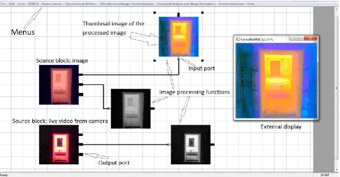
Figure 1 shows the GUI of the software. The user can easily select different image processing algorithms like filters, shape detection, edge detection etc. from the menu and connect the blocks to create some sophisticated algorithm. The software also supports multiple input sources such as: video streams, external cameras and images at the same time.
[image:3.595.125.473.434.615.2]The properties of each individual block can be set in real-time for fine tuning of the developed algorithms. For example, when the user changes the threshold function settings on a real-time video stream, the user can see the processed image and the effect of this change on other blocks. The processed image can also be displayed in an external window if required. The user can also set the initial value of each individual block separately. If any type of error or exception occurs when processing the input image, the program automatically holds the latest valid result, sets the output to zero or a null image or stops the program based on the settings specified by the user. The source of the error is also displayed to the user in real-time.
Figure 1. The GUI of the developed software.
3. Imaging Processing Capabilities
Cooke, National Instruments and PixelSmart. Using OpenCV the program supports all common image manipulations, including reading/writing of image files and videos, and operations on individual pixels, image regions or the whole image. It can perform basic operations such as convolution, edge detection, corner detection, line detection, shape detection, Fourier transform, histogram matching, and colour manipulation. It can also perform more sophisticated operations such as dilation, erosion, opening and closing of structures, mathematical operations on sets of images such as multiplication, colour space conversions (like converting from RGB to HSL and HSV). One of the strong points of the developed software is its ability to integrate with different industrial scale packages that support ActiveX.
4. General Architecture of the Software
[image:4.595.171.424.413.605.2]The software package has an internal doc/view architecture. It can be used in both dialog and doc/view applications due to the separation between the editor and data. The software has no dependencies other than MFC (Microsoft Foundation Classes) [7]. MFC provides an easy way to achieve portability among different operating systems and portability among different processors. If UNIX systems have the UNIX version of MFC, the developed code should port with the UNIX system without difficulty. We chose MFC to develop the target software to ensure its compatibility with recent and legacy industrial software that support ActiveX.
Figure 2. The hierarchical architecture of the software.
operations such as copying, pasting, undoing and serializing the data. It is completely separated from CMainEditor to allow doc/view architecture [7].
The graphical objects are all derived from a class called CImgaeBlocks. All the image processing blocks are derived from CImgaeBlock. CImgaeBlock object provides basic functionality for running image progressing functions, handling input and the processed data and generating a thumbnail from the processed data. Each graphical block is linked internally to an image processing function written in C++. Most of the underlying image processing functions are written using OpenCV.
To transfer data between blocks void pointers were used. Void pointers can point at objects of any data type. Using this method it is possible to transfer other data types like vectors, images and numbers between blocks. When connecting blocks together the software automatically casts the void pointer (output of the first block) into an appropriate type (input of the second block).
Every block is responsible for processing the input data and passing a void pointer of the processed data to the next connected block. If there is more than one processor available on the host target, the software will automatically use multithreading approaches (using OpenMP) to decrease the processing time.
The top layer vector graphics editor transfers the processed data between blocks and commands each block to process the new input data.
The drawing functionality of the software allows the user to see the processed image of each block in real-time. A thumbnail of the processed image is created and is displayed over the graphical block or on an external window (sees Figure 1). The user can switch the display functionality on or off for every individual block. Each block automatically creates a new thumbnail of the processed image every time new data arrives. This could increase the overall processing time significantly if many blocks try to display the thumbnail images. This functionality is mainly used in designing and testing the image processing algorithm and it is recommended to be switched off when using the software in real-time.
The software also provides debugging functionality to reduce the number of bugs or defects in the designed algorithm. The user can run the underlying C++ function of every single block separately or run the algorithm for only one cycle. The GUI also highlights the current active block for the user.
5. Testing the Software
Non-contact dimensional measurements of forging parts is desirable in real-time process control [8]. Accurate dimensional measurement can significantly improve the part handling when using robots to automate the process. To test the developed software a Sony camera was installed on an M-710IC series Fanuc robot. The robot was connected to a PC using GE Proficy software which is a universal development environment for operator interface, motion and control applications. The position of the robot was controlled through GE Proficy and the image processing platform was integrated into GE Proficy using ActiveX technologies. The acquired images were analysed in the developed software and the object location was reported to GE Proficy before the robot position was adjusted.
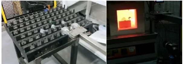
The whole system was tested for handling both at room temperature and hot (+1100ºC) parts. For the room temperature test, parts were place on a table as shown in Figure 3. The robot scanned the table and if a part was detected it adjusted its position to pick the identified part. In the hot test an object was placed inside a hot furnace (+1100ºC) for 30minutes and the object orientation was manually changed (15°) to simulate the object displacement inside the furnace. In both cases the robot vision system operated successfully proving the system was capable of detecting differences in position, adjusting it path to accommodate before picking the component (Figure 3).
6. Future Work
[image:6.595.145.450.336.443.2]Though the core of the software already exists, further work is required to develop new features especially machine learning algorithms and the addition of more functionality to control the robot movement based on captured images.
Figure 3. Left- Room temperature test. Right- Hot (1100ºC) test.
References
[1]ASM International, ASM Handbook: Volume 14A Bulk Forming. American Society for Metals.
[2]Appleton, E. H., Open die forging with industrial robots. Industrial Robot: An International Journal. Vol.
6(4), 191-194, 1979.
[3]Aksakal B., Analysis on a flexible forging cell. Indian Journal of Engi neering & Materials Sciences. Vol.
10, 113-122, 2003.
[4]Harrison, C. S., A review of automation in manufacturing illustrated by a case study on mixed-mode hot
forging. Manufacturing Rev. Vol. 15(1), DOI: 10.1051/mfreview/2014012. 2014.
[5]Togni, I. P., Automation of forging by means of robots. Industrial Robot: An International Journal. Vol
5(3), 121-122, 1978.
[6]Matuska, S., Hudec, R., & Benco, M., 2012. The comparison of CPU time consumption for image processing algorithm in Matlab and OpenCV. ELEKTRO, IEEE: Rajeck Teplice, 75–78. DOI:10.1109/ELEKTRO.2012.6225575, 2005.
[7]Shepherd G., Scot Wingo., MFC internals: inside the Microsoft foundation class architecture. Addison Wesley Longman Publishing Co., Inc. Redwood City, CA, USA, 1996.
[8]Zhenyuan Jia, B. W., An improved image acquiring method for machine vision measurement of hot formed