1876-6102 © 2017 The Authors. Published by Elsevier Ltd. This is an open access article under the CC BY-NC-ND license (http://creativecommons.org/licenses/by-nc-nd/4.0/).
Peer-review under responsibility of the organizing committee of GHGT-13. doi: 10.1016/j.egypro.2017.03.1810
Energy Procedia 114 ( 2017 ) 6800 – 6812
ScienceDirect
13th International Conference on Greenhouse Gas Control Technologies, GHGT-13, 14-18
November 2016, Lausanne, Switzerland
Considerations in the development of flexible CCS networks
Ben Wetenhall
a*, Julia Race
b, Hamed Aghajani
a, Eva Sanchez Fernandez
c, Mark Naylor
d,
Mathieu Lucquiaud
eand Hannah Chalmers
e*
a School of Marine Science and Technology, Newcastle University, Armstrong Building, Newcastle-upon-Tyne, NE1 7RU, UK. b Department of Naval Architecture, Ocean and Marine Engineering, University of Strathclyde, Glasgow, G4 0LZ, UK.
c School of Engineering & Physical Sciences, Heriot Watt University, Edinburgh EH14 4AS, UK.
d School of Geosciences, University of Edinburgh, The King's Buildings, James Hutton Road, Edinburgh EH9 3FE, UK. e School of Engineering, University of Edinburgh, Edinburgh EH9 3FB, UK.
Abstract
This paper discusses considerations for the design of flexibly operated Carbon Capture and Storage (CCS) pipeline networks and is based on the findings of the Flexible CCS Network Development project (FleCCSnet), funded as part of the UK CCS Research Centre. The project considered the impact of flexibility across the whole CCS chain, as well as studying the interfaces between each element of the system; e.g. at the entry to the pipeline system from the capture plant and at the exit from the pipeline to the storage site. The factors identified are intended to allow CCS network designers to determine the degree of flexibility in the system; allowing them to react effectively to short, medium and long term variations in the flow of CO2 from
capture plants and the constraints imposed on the system by CO2 injection and storage.
The work of the project is reviewed in this paper which explores the flexibility of power plants operating with post combustion capture systems; quantifies the available time to store (line pack) CO2 in the pipeline as a function of pipeline size,
the inlet mass flow rate and operating pressure; and explores the influence that uncertainty in injection and storage parameters have on the design of the pipeline. In addition, parameters influencing short and longer term network designs are discussed in terms of varying flow rates. Two practitioner workshops [1, 2] contributed to the direction of the project. The first workshop identified and confirmed key questions to be considered in order to understand the most likely impacts of variability in both the
* Corresponding author. Tel.: +44 191 208 5532
CO2 sources and CO2 sinks on CO2 transport system design and operation. The second workshop focused on transient issues in
the pipeline and storage site.
Although the case studies in the work are UK based, this work is applicable to other situations where large and small sources of CO2 are expected to be feeding into a CCS transportation system. The work is expected to inform a broad range of
stakeholders and allow network designers to anticipate potential problems associated with the operation of a CCS network. For an effective design of CCS infrastructure, all of the factors that will have a substantial impact on CO2 flow will have to be
analysed at an early stage to prevent possible bottle necks in the whole chain.
© 2017 The Authors. Published by Elsevier Ltd.
Peer-review under responsibility of the organizing committee of GHGT-13.
Keywords: Carbon Capture and Storage; flexibility; whole chain; storage interface; capture interface
1.Introduction
During normal operating conditions in a CCS system, the flow of CO2 from a point source (e.g. a power station) is expected to be governed by the load cycle of the source. For early CCS projects it is likely that the CO2 capture plant will run predominantly under steady state conditions. In this case, interruption to the flow of CO2 can occur in a controlled manner, e.g. during a planned outage, or in an uncontrolled manner, e.g. during a plant trip. As the energy and CCS market develops, it is likely that CO2 transportation networks will develop and CO2 capture plants will have to operate more flexibly. This will lead to a variability in CO2 flow into the CCS transport network, e.g. in response to increased usage of intermittent renewable energy in the electricity system. Storage sites can impose additional variability and constraints on the network through fluctuating injection volumes and potential upset conditions and/or maintenance requirements at the injection points. The aim of the FleCCSnet project was to investigate the effect that these constraints and variabilities could have on CCS pipeline network systems.
One important factor in the flexibility of a CCS system is the amount of temporary storage available in the system. FleCCSnet looked at the available temporary storage in the capture and pipeline transportation systems. A capture plant offers some degree of flexibility in a CCS system with potential for temporary CO2 storage available in, for example, CO2 absorbents. Findings of the project on the flexibility of post combustion capture systems are summarised in Section 2.1 which demonstrate that the flexibility of a post combustion capture plant is often oversimplified. To quantify the available storage in the pipeline network, the project looked at the influence of pipeline design on using the pipelines as a temporary storage vessel (known as line packing). The findings are shown in Section 2.2.
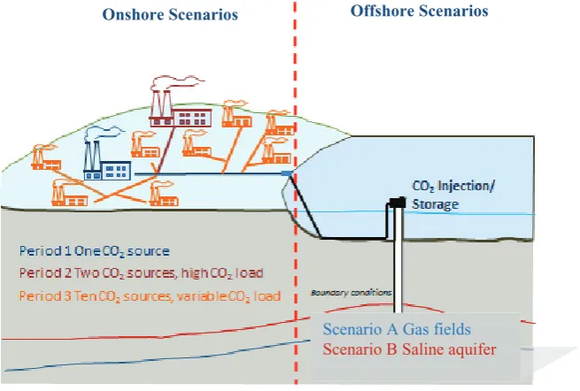
Constraints can also be imposed on a CCS pipeline network by offshore storage infrastructure. The store is typically a relatively inflexible part of the CCS chain since the possibility of modifying its characteristics is either limited or not possible. Behaviour of the storage site is split into two categories of boundary conditions at the wellhead (Scenarios A and B) as shown in Figure 1. Scenario A represents depleted open and closed hydrocarbon fields, while Scenario B represents saline formations. In an open reservoir, the average reservoir pressure is hydrostatic and the average pressure in the reservoir remains hydrostatic through the life time of the reservoir. In a closed reservoir, the average pressure is below hydrostatic. Saline formations have some similarities with open hydrocarbon reservoirs; however, there is more uncertainty on the characteristics of the store. The project looked at constraints caused by the storage site in terms of the influence that uncertainties in reservoir performance have on pipeline flexibility [3]. A summary of the findings is given in Section 2.3.
In order to be able to take into account flexibility requirements in pipeline network design, the project considered the effect that fluctuating volumes of CO2 entering a pipeline transportation network can have on the network during the evolution of a CCS system. To facilitate this, three periods (Periods 1, 2 and 3) were proposed to represent potential stages of CCS pipeline network development. Period 1 is a single source to sink pipeline (and represents, for example, a full scale demonstration project), Period 2 adds more complexity into the system by connecting two sources to a single sink via a trunk line pipeline and Period 3 has multiple sources connected to multiple sinks and is a representation a potential future CCS pipeline network. An illustration of the periods is shown in Figure 1.
© 2017 The Authors. Published by Elsevier Ltd. This is an open access article under the CC BY-NC-ND license (http://creativecommons.org/licenses/by-nc-nd/4.0/).
Figure 1 Schematic representation of the scenarios considered for FleCCSnet
The structure of the paper is as follows: previous findings of the project on the flexibility available in post combustion capture systems, the amount of line packing time available in terms of pipeline design and the effect that uncertainty of storage site parameters has on pipeline design are briefly reviewed in Section 2. Then in Section 3 the potential evolution of CCS systems is considered in terms of the impact that fluctuating volumes of CO2 entering the transportation system can have on network operation. This is presented in terms of three different time periods of CCS network development (Periods 1, 2 and 3). Finally in Section 4, the findings of the project (including the outputs from the workshops) are discussed in terms of the potential impact on flexibility in a CCS system.
2.Previous findings of the FleCCSnet project
This section briefly reviews previous findings of the project in order that their implications on designing a flexible CCS system can be considered.
2.1.Operational flexibility in power plants with post combustion capture
The capture plant plays a key role in governing the flexibility available in a CCS system as well as determining the quantity and quality of CO2 entering a transportation (and storage) system. The project looked at the available flexibility of supercritical coal power plants with amine based CO2 capture [4, 5] using a rigorous, fully-integrated model along with accurate assumptions about the capabilities of power plants to operate at part load and to regenerate additional solvent. Rigorously validated guidelines were published for the increasing number of techno-economic studies on power plant flexibility and CO2 flow profiles for studies on integrated CO2 networks. The work characterises the operating envelope, the performance and the corresponding compressed CO2 flow of coal power plants for a range of loads, with or without voluntary by-pass of the capture unit. For CCS power plants specifically designed for operational flexibility optimised part-load operating strategies are provided giving insights into additional flexibility. Further work could focus on different power plant and/or CO2 capture options and it is also
Onshore Scenarios Offshore Scenarios
important that CO2 capture from large industrial sources is considered when analysing the development of CCS networks.
2.2.Line packing time
Another way of introducing temporary storage in a CCS system is by using any pipelines as storage vessels whilst maintaining flow into the pipelines, this process is known as line packing and is commonplace in the operation of natural gas pipelines. The line packing capacity of a pipeline can be increased by increasing the internal volume of the pipeline, reducing the mass flow rate into the pipeline, increasing the wall thickness, increasing the yield stress properties of the pipeline material and by managing the inlet pressure and outlet pressures. The project studied the available line packing time of CO2 pipelines in terms of pipeline geometry, mass flow rate and line pressure and will publish relationships between these variables. These relationships allow an estimation of the line packing capability of a CCS pipeline network in terms of pipeline design and operation.
The work conducted indicates that a pipeline, with dimensions typical of those considered for CCS schemes, can provide short term storage of CO2 for around 10 hours. Because of the potential difficulties in storing CO2 in buffer storage for CCS systems (see Section 3.2), the level of flexibility for the pipeline to act as short-term storage in the network is very important and should be included in the design of a CCS network system.
2.3.Impact of storage uncertainty
The storage site can also impose constraints on a CCS pipeline transportation system. In terms of the North Sea, the FleCCSnet project looked at how uncertainty in CCS store properties (such as pressure, temperature, depth and permeability) can affect injectivity and lead to variations in CO2 flow that can impact transportation infrastructure [3]. The methodology used is also applicable to other locations and can be used for site screening to identify storage sites that offer greater flexibility in terms of uncertainty in store performance. The proximity of wellhead conditions to the CO2 equilibrium line and a maximum limit on velocities inside the well constrain the operational envelope of the storage site and may limit the ability of the storage site infrastructure to handle variations in CO2 flow coming into the store. These factors, which may be highly influenced by variations in subsurface conditions, can have an impact on the design of the pipeline infrastructure; for instance, being able to accommodate changes in pressure delivery requirements. The paper concludes that there is greater flexibility in stores with an initial pressure greater than 20MPa.
3.CCS network development in terms of the quantity of flow into the network
The amount of flow entering the transportation system is determined by the capture plant which, in turn, is governed by the operating pattern of the CO2 source. Important factors include operating cycle, plant efficiency (which may vary through the lifetime of the plant), plant configuration, amount of CO2 captured, equipment efficiency, intermediate process power requirements, such as for solvent regeneration, and also the type of fuel combusted, see for example [6]. The pipeline transportation system needs to be designed to accommodate the fluctuations in CO2 flow which are expected as a CCS system evolves. To investigate the effect of varying flow rate on pipeline networks on the timescales of Periods 1 and 2 (an initial source-to-sink pipeline followed by two sources connected to a single sink using a trunk line), three kinds of flow patterns were modelled on simple pipeline networks where power plant boiler ramp rates are assumed to be controlling the quantity of CO2 flow.
1) Case 1: Constant flow rate of 150kg/s then a smooth ramp down in flow to zero over 4500s (75 minutes) . 2) Case 2: A full cycle consisting of a smooth ramp up to 150kg/s over 4500s, constant flow at 150kg/s and
then ramp down to zero flow over 4500s†.
To explore the effect of varying loads on a Period 2 type network a ramp down of one of the sources is considered with the other source contributing a steady flow of CO2. The findings are then discussed in terms of how varying loads of CO2 can be accommodated in Period 3 type networks.
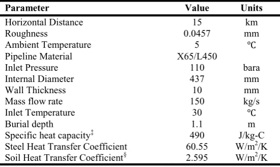
[image:5.544.130.405.226.390.2]To represent a Period 1 type network, a single source to sink pipeline transporting pure dense phase CO2 from a capture site along a flat terrain was chosen. A pipeline length of 15km was selected to show the effect of varying flow rates at a local level. The pipeline was designed to accommodate peak steady state flow, to avoid two phase flow and to comply with allowable stress and erosional velocity limits using the procedure as outlined in [9]. The top of the pipeline was buried 1.1m below the ground level and the surrounding soil temperature is 5oC which represents a UK winter scenario. Full details of the pipeline are given in Table 1.
Table 1: Period 1type network pipeline properties.
Parameter Value Units
Horizontal Distance 15 km
Roughness 0.0457 mm
Ambient Temperature 5 Ԩ
Pipeline Material X65/L450
Inlet Pressure 110 bara
Internal Diameter 437 mm
Wall Thickness 10 mm
Mass flow rate 150 kg/s
Inlet Temperature 30 Ԩ
Burial depth 1.1 m
Specific heat capacity‡ 490 J/kg-C
Steel Heat Transfer Coefficient 60.55 W/m2/K Soil Heat Transfer Coefficient§ 2.595 W/m2/K
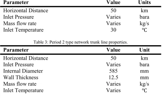
To illustrate the effect of varying flow on a Period 2 type network, a pipeline network consisting of two emitters connected to a single sink by three pipelines was chosen. This type of network is illustrated inFigure 2. Again, the pipelines are designed to accommodate peak steady state flow following the same procedure as above. Details of the pipelines are shown in Tables 2 and 3 (properties that are identical to those of the source to sink pipeline are omitted). The pipelines in the Period 2 network were selected to be 50km in length to be more representative of what could be found in CCS systems.
Figure 2: Schematic of Period 2 type network containing two sources, two feeder pipelines and one trunk line pipeline.
†The ramp down and ramp up rates were confirmed by experts and are based on typical ASC PC boiler ramp rates.
Modelling of the pipeline networks was conducted using the transient flow package OLGA [10, 11] using the single-component, two-phase (liquid and gas) CO2 module with the Span and Wagner equation of state [12]. OLGA solves the conservation equations for mass, momentum and energy for the gas, liquid droplet and liquid film phases at discrete points in time and distance. The numerical procedure uses the finite difference method with the pipeline divided into segments and a solution is sought at the centre of each segment. Following a sensitivity analysis, the source to sink (Period 1 type) and two emitter (Period 2 type) pipeline networks, were discretised in OLGA into 10,000 and 50,000 segments respectively.
To show the effect that the loading patterns have on the pipeline networks, readings of mass flow rate and pressure were taken at the inlet and outlets of the source to sink pipeline as well as the inlets and outlets of each branch of the two emitter network.
Table 2: Period 2 type network feeder pipeline properties.
Parameter Value Units
Horizontal Distance 50 km
Inlet Pressure Varies bara
Mass flow rate Varies kg/s
[image:6.544.134.411.205.373.2]Inlet Temperature 30 Ԩ
Table 3: Period 2 type network trunk line properties.
Parameter Value Unit
Horizontal Distance 50 km
Inlet Pressure Varies bara
Internal Diameter 585 mm
Wall Thickness 12.5 mm
Mass flow rate Varies kg/s
Inlet Temperature Varies Ԩ
3.1.The effect of constant CO2 flow followed by a ramp down on a Period 1 network
Figure 3: Mass flow rate profile at the inlet and end of the pipeline for a ramp down type load.
3.2.Modelling one shift in flow on a Period 1 network
On the same source to sink pipeline network, a shift (ramp up in flow, then constant flow followed by a ramp down) loading pattern was simulated (Case 2). The flow rate starts at close to zero and then gradually (increases to the full load of 150kg/s at a rate of 2kg/s per 60s. After 2400s, when the flow has reached steady state, the mass flow rate decreases gradually at the same rate. The ramp up and ramp down takes 4500s to complete and the full simulation time is 36000s (600 mins).
[image:8.544.68.476.276.545.2]Figure 5 shows the mass flow rate profile at the inlet and outlet of the pipeline as the flow into the pipeline follows the loading pattern. Because the pipeline is full of fluid when the simulation begins, the mass flow rate of the outlet of the pipeline temporarily increases above 150kg/s to around 170kg/s. The flow then becomes steady state at about 1680s (280mins) and during the ramp down both the inlet and outlet show the same flow patterns with the outlet again lagging the inlet. Figure 6 shows the pressure distribution at the inlet and outlet of the pipeline over the simulation time. The pressure at the inlet is again maintained at 110bara and the outlet pressure close to 110bara (when the mass flow rate is close to zero). As the mass flow rate is increased the pressure drop across the pipeline increases accordingly and, as steady state operation is reached, the outlet pressure approaches 107.5bara. During the ramp down, the outlet pressure climbs up to 110bara again, as the mass flow rate reaches approaches 0kg/s.
Figure 6: Pressure profile at the inlet and end of the pipeline for a cyclic type of load pattern.
This demonstrates that a pipeline will follow the flow of the capture plant with a slight delay and that there will be some residual CO2 left in the pipeline after the flow rate drops to zero. Single phase operation can be maintained as long as the pressure in the pipeline is maintained (for example using shut in valves). Reducing the flow will reduce pressure loss through the pipeline and flow velocity.
For this source to sink case, a complete drop in flow into the pipeline means that flow to the storage site will be interrupted. To mitigate for this flow could be choked at the storage site. There is also some potential to line pack the pipeline, although not as much margin as in natural gas pipelines (see Section 2.2). It is important to note that it is also difficult to mitigate for this using compressors as compressors are generally inflexible in terms of the range of flow rates and pressures they can accept. If CO2 needs to be recirculated this also has large implications for cost and energy requirements due to extra cooling and pressure control [13]. Another way around this is to use buffer storage along the pipeline route. However to do this in pressure vessels, onshore and at the necessary scale could prove very difficult because of space and safety requirements. Additionally, some studies have concluded that buffer storage in a saline aquifer offshore is also unadvised [14].
3.3.The effect of varying flow patterns on a Period 2 type network and the Repercussions for larger networks
flow in the network is shown in Figure 7 at the inlets and outlets of all three sections of pipeline. The flow from the second source flows at 150kg/s for 1200s (20mins) to allow for steady state conditions to be reached, reduces to 30kg/s at a rate of 1kg/s per 60s and then then stays at 30kg/s for 3000s (50mins) so that the flow can return to a steady state condition. The whole flow cycle takes 60000s (1000mins) to complete. The pressure profile at the same locations in the network is shown in Figure 8. The flow patterns of the reducing source and the trunk pipelines show similar patterns with an (expected) lag. After the ramp down of the second source, the flow in and out of the trunk line starts to approach the same value as steady state is reached (around 55000s). The outlet pressure of the trunk line is maintained at 94bara in order to be able to maintain single phase flow, while the inlet pressures of the first and second sources drop with the drop in flow of the second source to balance the pressures in the network with both having an initial pressure of 110bara, the first source’s inlet pressure dropping to 104bara and the second source’s inlet pressure dropping to 96bara. There is a corresponding smooth drop in pressure of the trunk line from an inlet pressure of 101bara to an inlet pressure of 96bara. This illustrates the importance of having some control over pressure management in CCS systems in order to be able to compensate for fluctuating volumes of CO2. It is also interesting to note that once the flow into the second line has ceased and steady state conditions have been reached (which takes around 47000s) CO2 is being stored in the second line. The quantity of CO2 that can be stored in this way is dependent on the line packing capability of the pipeline (see Section 2.2).
Figure 7: The mass flow rates in the Period 2 type network at various locations in the network.
This case demonstrates that, with more active sources connected into a CCS network, network management in terms of maintaining flow into the storage site is made easier. As would be expected, the flow is dominated by the emitter with the highest flow rate and flow can be easily maintained as long as both emitters are not shut off at the same time. However, the pressure in the system has to be carefully managed in order to keep the network flowing smoothly.
but would prove more difficult in more congested areas. It is expected that changes in load will affect mainly compression operation in terms of changing pressure delivery requirements as illustrated in the Period 2 network example.
[image:11.544.56.479.182.520.2]Longer CO2 pipelines give longer response times even though the project has demonstrated that there is not as much scope as in natural gas pipelines for line packing if CO2 is being transported in the dense or supercritical phase. Also, there may be scope for bigger networks to have fewer problems in terms of flexibility, particularly where the use of multiple sources/sinks allows several viable operating options to be identified. As noted earlier, interim CO2 storage could prove difficult and the use of the pipeline as a means of temporary storage is therefore a key consideration in the design of a CCS system. It is also noted that if there is to be any reuse of infrastructure the extent of flexibility in the system should be considered (e.g. the amount line packing that is available).
Figure 8: The pressure profile of the Period 2 type pipeline network at various locations in the network.
4. General considerations for the operation of a flexible CCS network
In this section some further considerations that should be taken into account when designing a CCS system are presented, including the phase in which the CO2 is transported and the flexibility of the system.
difficulties in operation. For example, a booster station designed for a compressible fluid can be damaged by using gaseous phase CO2. Two phase flow occurs in a pipeline when the fluid crosses a phase boundary; this is dependent on the composition of the CO2 stream (see, for example, [15]). There are a number of possibilities than can cause the crossing of a phase boundary [16]. In dense phase pipelines it can be caused by having too large a mass flow rate which increases pressure drops in the pipeline in order to continue to drive the flow forward. If the pressure drops are too large the bubble point line will be crossed. This can be mitigated by increasing the inlet pressure, as long as the allowable stress design limits for the pipeline are not exceeded. It is also possible for dense or gaseous phase flow to become two phase due to the fluid changing temperature. It is important to know the expected pipeline surrounding temperatures so that this can be mitigated. In gaseous phase transportation, temperature plays a more important role due to the proximity of the dew point line to ambient temperatures.
The work of this paper was conducted using pure CO2; however the composition of the CO2 stream is extremely important and will affect each part of the CCS chain (see for example [9, 15, 16]) and how they interact with one another.
As discussed earlier, in general the larger the transportation network, the greater the amount of flexibility exists in the whole CCS chain and the more options could be available to manage the interfaces between the transportation network and the capture and storage sites. This can be in terms of amount of line packing time but also because of the increased number of wells and increased flow in the network. In larger networks, there are more options for dealing with the effects of capture plant shut-down or storage shut-down since it would be easier to maintain partial operation of the CCS network.
CCS systems need to be able to accommodate maintenance cycles for all aspects of the CCS chain. For example, well maintenance is typically carried out on a 12 monthly or 6 monthly basis and maintenance at power plants is generally staggered (which would result in lower impact on the CO2 flow into the transportation network). There is a need to anticipate expected transportation volumes of CO2 as accurately as possible to ensure an efficient design of a transportation network; this includes the need to consider the impact of renewable energy on the electricity grid and the potential CO2 load profiles that will be seen.
Flexibility will be impacted if the network is designed with trunk lines. In this case there are greater constraints regarding where the CO2 flow can be directed. Also, the greater the flow into the trunk line, the less line packing time there will be available. Designers and planners will need to consider the pros and cons of laying one large pipeline or smaller pipelines, potentially at different times.
5. Conclusions
The FleCCSnet project considered the sources of potential flexibility in whole chain CCS systems, including the interfaces between the transportation system and the capture plant and storage sites. In Section 2.1, work on post combustion capture plant flexibility was highlighted and the project showed levels of flexibility are often understated. As discussed in Section 3, as size of a CCS system increases there are more options to manage the system in terms of flow of volumes of CO2 given that adequate pressure management options exist in the system (for example, flexibility in the delivery pressure of a compressor). With more flow in the system it is likely that it will be easier to manage flow into storage sites as it will be easier to maintain minimum flow in the majority of the CO2 transportation system.
In Section 2.3 it was stated that the capability of the store is affected by uncertainties in the characteristics of the store. One way of mitigating these uncertainties is to use intermediate temporary storage in the system. Section 2.2 showed that there is some capability to store CO2 in the pipeline in the form of line packing but at reduced levels as compared with natural gas. Buffer storage of CO2 in the system either in pressurised vessels onshore or saline formations along the pipeline route is possible but could be very difficult to implement .Therefore, the capability of the pipeline system to act as short-term storage in the network is very important and should be considered in the design of system. It is highlighted that this capability should also be considered if there is to be any reuse of pipeline infrastructure.
can develop organically with the use of a properly sized trunk pipeline with the fluctuations in volumes of CO2 being dealt with using pressure management. However, it is important to note that the fluctuations in flow can still impact on storage side operation; this needs to be considered in more detail in future work.
Acknowledgements
This work was funded by the UK CCS Research Centre through its Call 1 for project proposals (UKCCSRC-C1-40). The UKCCSRC is supported by the EPSRC as part of the Research Councils UK Energy Programme. The authors are grateful to the Research Centre for providing this funding. Financial support for Dr. Mathieu Lucquiaud through the Royal Academy of Engineering Research Fellowship is gratefully acknowledged. The authors would also like to thank Schlumberger for the donation of the OLGA software program through the Schlumberger University Donation scheme and all the workshop attendees for their contributions to the project.
References
[1] Developing CO2 networks: Key lessons learnt from the first Flexible CCS Network Development (FleCCSnet) project workshop. Report from
the first Flexible CCS Network Development (FleCCSnet) project workshop, Edinburgh, 30/04/2014, https://ukccsrc.ac.uk/resources/ccs-projects-directory/flexible-ccs-network-development-fleccsnet.
[2] Developing CO2 networks: Scenarios building on the first Flexible CCS Network Development (FleCCSnet) project workshop. Report from
the first Flexible CCS Network Development (FleCCSnet) project workshop, Edinburgh, 30/04/2014, https://ukccsrc.ac.uk/resources/ccs-projects-directory/flexible-ccs-network-development-fleccsnet.
[3] E. Sanchez Fernandez, M. Naylor, M. Lucquiaud, B. Wetenhall, H. Aghajani, J.M. Race, H. Chalmers, 2016. Impacts of geological store uncertainties on the design and operation of flexible CCS offshore pipeline infrastructure. International Journal of Greenhouse Gas Control Volume 52, September 2016, Pages 139–154.
[4] M. Lucquiaud, E. Sanchez Fernandez, H. Chalmers, N. Mac Dowell, J. Gibbins Enhanced, 2014. Operating Flexibility and Optimised Off-design Operation of Coal Plants with Post-combustion Capture, Energy Procedia Volume 63, 2014, Pages 7494–7507.
[5] E. Sanchez Fernandez, M. Sanchez del Rio, H. Chalmers, P. Khakharia, E.L.V. Goetheer, J. Gibbins, M. Lucquiard, 2016. Operational Flexibility Options in Power Plants with Integrated Post-Combustion Capture. International Journal of Greenhouse Gas Control, Volume 48, Part 2, May 2016, Pages 275–289.
[6] J. Gibbins and H. Chalmers, 2008. Carbon capture and storage. Energy Policy, 36, 4317-4322.
[7] E. Sanchez Fernandez, E.LV. Goetheer, G. Manzolini, E. Machhi, S. Rezvani, T.JH. Vlugt, 2014. Thermodynamic assessment of amine based CO2 capture technologies in power plants based on European Benchmarking Task Force methodology. Fuel, 129, 318-329.
[8] A.R.W. Bruce, G.P. Harrison, J. Gibbins, H. Chalmers, 2014. Assessing Operating Regimes of CCS Power Plants in High Wind and Energy Storage Scenarios. Energy Procedia, Volume 63, 2014, Pages 7529-7540, 12th International Conference on Greenhouse Gas Control
Technologies, GHGT-12.
[9] B. Wetenhall, H. Aghajani, H. Chalmers, S.D. Benson, M-C. Ferrari, J. Li, J.M. Race, P. Singh, and J. Davison, 2014b. Impact of impurity on CO2 compression, liquefaction and transportation. Energy Procedia, 63, 2764-2778.
[10] SCHLUMBERGER, 2014. OLGA software version, 7.3.4.
[11] M. Havelsrud, 2012. Improved and verified models for flow of CO2 in pipelines. The 3rd International Forum on the Transportation of CO2
by Pipeline, Clarion Technical Conferences, Newcastle, UK.
[12] R. Span R and W. Wagner, 1996. A new equation of state for carbon dioxide covering the fluid region from the triple-point temperature to 1100K at pressures up to 800MPa. J Phys Chem Ref Data 1996; 25(6): 1509-1596.
[13] IEAGHG, 2012. Operating Flexibility of Power Plants with CCS, 2012/6, June, 2012.
[14] R. Kaufmann, I. Aavatsmark, P. Helge Nøkleby, T.A. Aurdal, 2016. Using an aquifer as CO2 buffer storage. International Journal of
Greenhouse Gas Control Volume 53, October 2016, Pages 106–116.
[15] B. Wetenhall, J.M. Race, M. Downie, 2014. The effect of CO2 purity on the development of pipeline networks for carbon capture and
storage schemes. International Journal of Greenhouse Gas Control, 30, p. 197-211.
[16] J.M. Race, B. Wetenhall, P.N. Seevam, M.J. Downie, 2012. Towards a CO2 Pipeline Specification: Defining Tolerance Limits for