Designing for Damage Stability beyond Design Level
Dracos Vassalos
1, Evangelos Boulougouris
2, Donald Paterson
3and Markku Kanerva
41
University of Strathclyde, [email protected]
2
University of Strathclyde, [email protected]
3
University of Strathclyde, [email protected] 4
Consultant, [email protected]
ABSTRACT
This paper describes the background and provides the rationale and the framework to embrace all feasible measures (passive/design and active/operational – nor-mal and emergencies) for improving the damage sur-vivability of RoRo Passenger ships. The ideas elaborat-ed in the paper is an attempt to elucidate and assess the impact on options for new and existing ships of increas-ing the required subdivision index R, the former in re-sponse to the higher damage stability standards recom-mended following the conclusion of the EMSA III pro-ject and the latter in case IMO decided to apply higher damage stability requirements retrospectively, particu-larly in the aftermath of an accident. Such a framework would provide the motivation for instigating and estab-lishing novel damage stability enhancing paradigms in line with IMO Circular 1455 on equivalents, for alter-native compliance. This, in turn, would enable the in-dustry to focus on all credible measures for damage stability enhancement in case of a flooding accident. This represents a step change both in the mind-set of naval architects and in safety legislation but the impact will be immense and mostly positive. This paper paves the way in this direction by providing the background and rationale for such a framework and by introducing an alternative system for damage stability enhancement that involves injecting highly expandable foam in the compartment(s) undergoing flooding during the intimal post-accident flooding phase thus enhancing damage stability and survivability of RoPax vessels well beyond the design levels in the most cost-effective way currently available. This is a mind-set changing innovation that is likely to revolutionise design and operation of most ship types and RoPax, in particular. A number of applica-tions are considered in the paper for a range of ship sizes with impressive results that will challenge the cur-rent established practice.
INTRODUCTION
Back in 1912 when RMS Titanic was sailing from South-ampton, UK to New York, USA, the airplane had just been invented 9 years ago by the Wright brothers and ships were still using coal. The tragic loss of 1,513 people onboard a state-of-the-art for its time ship was a shock for the society and the maritime industry. This led to the adoption of the first International Convention for the Safety of Life at Sea (SOLAS) of 1914, which over the last century is constantly improved and enhanced in its latest 1974 form. As a result, the shipping losses have been reduced from 1 ship per 100 per year back in 1912 to about 1 ship per 672 per year in 2014 (Allianz, 2015). Still, the societal outcry that follows every accident, especially in the case of passenger ships is tremendous with more recent examples the loss of Costa Concordia and Sewol. Tragedies such as these remind to both industry and academia that we have to do more in order to reduce the vulnerability of our ships in case of flooding. Unfortunately, our “arsenal” is still an enhanced version of the one that the naval architects had back in the dawn of the 20th century. Furthermore, due to the “grandfa-ther clause”, major changes to SOLAS are applied mainly to newbuildings, which represent obviously a small fraction of the existing fleet. Thus, the state-of-the-art knowledge on damage stability inoculates very slowly the fleet at risk, leaving most of the ships with severe vulnerabilities and their passengers and crew unnecessarily to higher risk. This becomes even more woeful considering the continuously accelerating pace of today’s scientific and technological developments. As a result, our regulatory framework is becoming progressively less relevant and unable to keep up with this pace of development.
designed with regards to their damage stability characteris-tics.
This paper presents an alternative system for damage stabil-ity enhancement that involves injecting highly expandable foam in the compartment(s) undergoing flooding during the initial post-accident flooding phase thus enhancing damage stability and survivability of ships and especially RoPax vessels well beyond the current design levels in the most cost-effective way possible.
BACKGROUND
Since the introduction of the probabilistic model for the assessment of the survivability of ships and especially dur-ing the last 15 years there have been multiple attempts from the industry and the academia to optimise the design of RoPax ships with multi-criteria design optimisation, using survivability after damage as an objective (Boulougouris, 2004). In R&D projects such as ROROPROB (2000-2003), GOALDS (2009-2012) and more recently in the EMSA 3 study (EMSA, 2015), the designers attempted to maximise the attained subdivision index for RoPax vessels of vari-ous sizes. In most of these cases, the designers had to in-crease the breadth or the freeboard of the vessel by few centimetres, add bulkheads under the main deck, subdivide the car deck or add cross flooding devices in order to achieve tangible improvements in the attained subdivision index (EMSA, 2015). The problem is that many of these design changes proved to be not cost effective risk control options (RCOs) due to their high cost or their low risk re-duction, surpassing the Net Cost of Averting a Fatality (NCAF) of 8mil USD (≈5.9mil€) which is widely accepted nowadays in the maritime industry (EMSA, 2015). These solutions have a significant impact on the CAPEX, OPEX, FUELEX, loss of revenues, but they may also have impact to the costs related to air emissions, upstream processes, climate change, harbour fees, salvage and loss of cargo. It is therefore obvious that the designers need new ‘tools’ in order to optimise their designs in a cost-effective way. Damage Stability Recovery System (DSRS) is such a solu-tion.
VULNERABILITY
"Vulnerability" as concept is used extensively in the sur-vivability assessment of naval ships (Boulougouris et.al., 2016) but in merchant shipping is used as a term in the 2nd Generation of Intact Stability Criteria without been directly associated to probability. Hence, a definition here is in order. The way this term has been used for merchant ships at Strathclyde relates to "the probability that a ship may capsize or sink within a certain time when subjected to a feasible extreme flooding case" (Vassalos, 2014). In the probabilistic framework, it could be defined as:
vi = 1 – si (1)
where si is the probability of survival of the vessel in a
particular damage case i. Therefore, vulnerability contains (and provides) information on every parameter that affects damage ship survivability. As a consequence, vulnerability is directly linked to risk. Using the probabilities of
occur-rence of each damage case, the total risk of losing the ves-sel in case of damage can be calculated:
Total Risk =∑( ∙ ) (2)
Similarly, the local risk associated with a particular damage case i can be calculated as:
Local Risk = ∙ = ∙ (1 − ) (3)
[image:2.595.314.546.282.424.2]Vassalos (2012) underlines that the ship, as a system with multiple operational modes and conditions, has some de-sign (nominal) characteristics and a number of operational ones which may modify its survivability at any given time (e.g. loading condition, open watertight doors, addition of cross flooding valves etc.). In that respect we should dis-tinguish the design vulnerability of the ship to the opera-tional one. An excellent example is the vulnerability distri-bution of MV Estonia shown at her design condition (Fig. 1) and at the time of her accident (Fig. 2).
Fig. 1 MV Estonia - Design Vulnerability distribution (Vassalos, 2012)
Fig. 2 MV Estonia - As Operated at the Time of her Loss (Vassalos, 2012)
Reducing the vulnerability beyond the levels achievable by adding another bulkhead, closing the watertight doors or using cross flooding, requires a system that can provide some of lost buoyancy. DSRS is that system.
DAMAGE STABILITY RECOVERY SYSTEM (DSRS)
[image:2.595.311.544.450.612.2]post-accident flooding phase. It has been developed (patent pending) by the University of Strathclyde with the support from Scottish Enterprise. It can be fitted to new or retrofit-ted to existing ships in order to reduce the likelihood of capsize/sinking and progressive flooding following a major flooding accident.
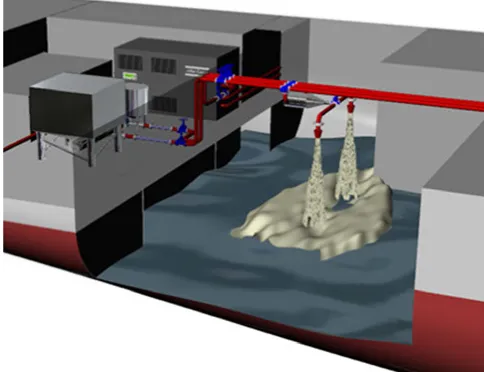
The working principle of the proposed system is simple: when a vessel is subjected to a critical damage, stability is recovered through the reduction of floodable volume within the vessel’s high risk compartment(s). This is achieved by rapidly distributing fast setting, high expansion foam to the protected compartment(s), regaining lost buoyancy whilst also eliminating free surface effects and forming a near watertight seal over unprotected openings. Moreover, with water being constrained low in the ship, it actually increas-es damage stability (higher GM).
[image:3.595.41.283.404.590.2]The system itself consists of a fixed supply of both foam resin and hardener agents; each stored within an individual tank and connected to a piping network for distribution. Different foam types have been considered and can be used depending on the specification of the system and the re-quirements of the owner. For generic version of the system (see Fig. 3 and 4) the operation starts when two distribution pumps supply a flow of filtered sea water into individual resin and hardener lines. Both streams are then dosed with concentrated resin and hardener agents, before they each pass through a static mixer in order to produce a homoge-neous solution of each component.
Fig. 3 System Representation
The two lines are then fed to the protected compartment where they meet and enter a foam generator. Here both streams mix and compressed air is introduced into the sys-tem for the in situ production of foam. The foam is then passed in to a branched piping network within the vulnera-ble compartment where both port and starboard side branches allow the foam distribution to the flooded room.
The whole process is monitored and controlled by a central system linked to vital components and sensors. The system can cover one or multiple compartments and may have sufficient capacity for one or more compartments. The use
of the system is under the full control of the crew, with a decision support system (DSS) available to help the ship’s master decide where and when the system will act as well as inform all concerned of the ensuing actions.
The foam compound, the resin and the hardener meet all the environmental and health criteria, they is not harmful to humans and the foam’s release does not pose any danger to the people onboard or the environment. Furthermore the foam is non-flammable and in this respect could reduce risk by other event sequences such as a fire ignited in collision. The residual clean-up post system discharge is also aided by a foam dissolving agent ensuring minimal business in-terruption.
METHODOLOGY
For the purposes of this study two ROPAX vessels, cur-rently operating in European waters, have been investigated with a view to assess the effectiveness of the proposed Damaged Stability Recovery System (DSRS) as a risk re-duction technology. The probabilistic approach to damage stability (SOLAS 2009) has been used as a means of estab-lishing the initial level of risk associated with the designs. The effects of the DSRS have then been modelled and the vessels were re-examined in order to assess the risk reduc-tion achieved by the system.
DSRS IMPLEMENTATION & MODELLING
In order to ascertain the impact of the proposed system on vessel safety, the designer has to identify the overall risk level associated with the vessel. From Eq. 2 we can easily associate the attained index A with the overall risk as:
= 1 − (4)
This provides a benchmark to gauge any improvements on the vessel’s safety achieved by the use of the DSRS.
[image:3.595.315.548.587.734.2]In order to ensure the system is designed in the most effi-cient manner, the system must target those compartments which represent the “Achilles heel” for the vessel i.e. con-stitute the greatest risk. As such, a risk profile of the vessel is created in order to aid in the identification of design vul-nerabilities.
The results from the probabilistic damage stability assess-ment provide a straightforward way of determining the vessel’s risk profile by firstly considering the local risk associate with each damage scenario, as calculated by Eq. 3. These local risk values are then mapped across the vessel according to damage centre, in order to form the risk profile as shown in Fig. 4.
In the above risk profile, risk is plotted on the vertical axis and the damage position along the horizontal. Differing lengths of damage, as measured by multiples of adjacent zones, are distinguished by marker type and colour. This enables the identification of both safety critical design spots and opportunities where safety could be improved most significantly and efficiently. Two cases in particular, circled in Fig. 4, are identified as large risk contributors. As such, it can be reasoned that the DSRS would be best applied in the protection of one if not both of the compartments which give rise to this risk. Following this methodology for the sample vessel, the system could be applied in the most efficient and effective manner.
For the analysis, the vessel should initially be modelled accurately according to its nominal (design) conditions. Data such as lines and general arrangement plans are re-quired. The relevant stability documentation is used in order to ensure that all unprotected and weather tight open-ings are taken into account. Loading condition information within the vessel’s stability booklet is used in conjunction with the damage stability metacentric height (GM) limiting curves in order to select the SOLAS 2009 initial loading conditions.
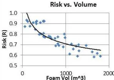
The required volume for the DSRS system is calculated through trade-off analysis of protected compartments’ per-meability. The required volume of foam is then estimated based on the minimum volume required to save the ship in the most demanding high risk damage scenario. The opti-mum volume can be estimated based on an Cost-Benefit Analysis (CBA) taking into account the cost of the system, the additional weight, the loss of carrying capacity (if any), and the achieved reduction of the risk as a function of foam volume, up to the threshold of the NCAF. Benefits from e.g. changing the payload distribution (e.g. more passengers) or increase in the earning potential of the ship due to im-provements to the hotel arrangements should also be in-cluded. An example of the trade-off between foam volume and risk is shown in Fig. 5.
Fig. 5. Trade-off analysis between foam volume and Risk
Following the analysis of a significant number of existing designs it has been proven that in the large majority, using the foam in one and two compartment would be sufficient for reducing substantially the risk of capsizing or founder-ing in case of damage. Two of these studies will be pre-sented here below.
CASE STUDY: LARGE ROPAX
Overview
Starting from the most demanding in terms of foam volume requirements case, the DSRS team studied a large ROPAX with a central cased ro-ro deck suitable for drive-through operations, with a large lower hold spanning eight com-partments under the main deck (see Fig. 6). The vessel is equipped with a hoistable car deck suitable for additional car storage.
[image:4.595.317.554.392.709.2]The vessel was built in 1998 to a two-compartment subdi-vision standard according to SOLAS 90’ along with Stock-holm agreement compliance with a significant wave height of 2.9m. Below the bulkhead deck the vessel is divided into a total of twenty water tight compartments and has pro-nounced B/5 subdivision spanning almost the entire length of the vessel and cross flooding ducts fitted to enable sym-metrical flooding. The vessel’s principal particulars and general arrangement are provided in Table 1 and Fig. 6.
Table 1. Principal Particulars
Fig. 6 General Arrangement
Length o.a (m) 200.65
Length b.p (m) 185.4
Breadth (m) 25.8
Draught MLD. (m) 6.8
Displacement (t) 19468
Deadweight (t) 5830
Crew Number 200 persons
[image:4.595.43.234.608.742.2]DSRS impact assessment
[image:5.595.42.286.117.187.2]In order to assess the damage stability performance of the vessel a total of 942 damage cases have been analysed under three loading conditions as outlined in Table 2.
Table 2. Loading Conditions
Displacement (t) Draft (m) GM (m)
LC1 (dl) 19468 6.8 2.226
LC2 (dp) 17412 6.4 2.003
LC3 (ds) 15087 5.733 3.191
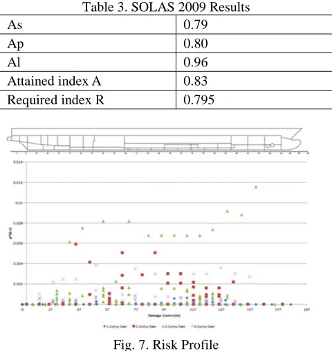
[image:5.595.312.553.130.370.2]The results of the SOLAS 2009 damage stability assess-ment along with the required index value calculated for this vessel can be found in Table 3 below. The risk profile de-rived for the vessel is also provided in Fig. 7. It is obvious that the SOLAS 90 + WOD requirements provide the ves-sels with sufficient survivability in order to fulfil easily the SOLAS 2009 requirements.
Table 3. SOLAS 2009 Results
As 0.79
Ap 0.80
Al 0.96
Attained index A 0.83
Required index R 0.795
Fig. 7. Risk Profile
Still, a closer inspection of the vessels risk profile reveals several vulnerabilities existing within the vessel’s design. This risk is founded primarily by damages that penetrate beyond the B/5 longitudinal bulkhead of the lower hold. Damages involving this space were not covered by the regulations in place at the time although they do however present a significant threat to the vessel’s safety.
Damage to the lower hold gives rise to large scale flooding leading to a significant reduction in the vessel’s residual stability. Having been identified as the largest risk contrib-utor this space was selected for the application of the sys-tem.
The volume of foam required in this case was defined as that required to mitigate the risk stemming from two com-partment damages involving the lower hold, equating 2000 m3 expanded volume. The damage stability performance
was then re-assessed following a permeability change to the lower hold to account for the effects of the foam.
The new attained index values calculated in this case can be found in Table 4 along with the updated risk profile of the vessel highlighted in Fig. 8.
Table 4. Attained Index after DSRS usage in 1-comp
Al 0.96
Ap 0.85
As 0.84
New Attained Index A 0.87
Fig. 8. Updated Risk Profile
It is clear from the newly calculated results that the effects of the system have resulted in a substantial reduction of risk. This is evident in the eradication of the risk contribution made by one and two compartment damages involving the vessel’s lower hold. The risk stemming from three com-partment damages to this space has also been mitigated, particularly in those damages located closer to amidships. However, there still exists a series of high risk three com-partment damages towards the fore of the lower hold and mitigation of these risks would call for a larger volume of foam to be utilised. In total the system has resulted in a 24% risk reduction from 0.17 to 0.13 for a 1-compartment DSRS application.
Selection of the second compartment for system protection involved re-evaluation of the vessel’s risk profile. Through doing so, the vessel’s main engine room was identified as the largest of the remaining risk contributors. This particu-lar space has a particu-large volume coupled with a high permea-bility value leading to large scale flooding when damaged and serious diminishment of the vessel’s residual stability.
[image:5.595.43.283.290.544.2]The damage stability results following this process are provided in Table 5 and the vessel’s updated risk profile is provided in Fig. 9.
Table 5. Attained Index after DSRS usage in 2-comp
Al 0.97
Ap 0.86
As 0.85
[image:6.595.321.544.44.377.2]New Attained Index A 0.88
Fig. 9. Updated Risk Profile
The results in this case show that the protection of two compartments has worked to mitigate the risk stemming from damages to the main engine room but failed to eradi-cate these risks. In total, there has been a relative 5% addi-tional risk reduction afforded by this further protection. In order to generate a more meaningful reduction in risk, ei-ther a larger volume of foam would be required or the range of compartments served by the system would have to be increased. The system was however able to produce an overall risk reduction of almost 30% from 0.17 to 0.12.
CASE STUDY: SMALL ROPAX
Overview
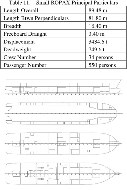
Investigating the effectiveness of the DSRS on the other end of the scale, a small ROPAX vessel was studied. It has side casings that run its length and the aft portion is open to allow the transportation of hazardous cargo. The vessel can accommodate a maximum of 550 passengers and is operat-ed by a total of 30 crew members. The vessel was launchoperat-ed in 2010 fulfilling the probabilistic SOLAS 2009 standard along with the “water on deck” deterministic requirements mandated by the EU passenger ship directive 2003/25/EC (EC, 2003). The vessel is divided into three main vertical fire zones and subdivided into 12 watertight compartments below the bulkhead deck. Lifesaving appliances are pro-vided for all 584 persons on board for domestic voyage, as a Class B vessel according the EU passenger ship directive 2009/45/EC. The vessel is not equipped with life boats. The principal particulars of the vessel are provided in Table 11 below along with the GA in Fig. 10.
Table 11. Small ROPAX Principal Particulars
Fig. 10. Small ROPAX GA
DSRS impact assessment
For the assessment of the vessel’s damage stability perfor-mance a total 533 damage cases were considered at three loading conditions. The results of the risk profile generated for the vessel in Fig. 11.
[image:6.595.43.285.95.337.2]The results from the damage stability assessment show a large disparity between the attained index value calculated and the required index value for the vessel (see Table 12). In this case the vessel’s is GM is limited dominantly across the three loading conditions by the requirements of the 2008 IS code and as such the attained index value is much higher than that required by SOLAS 2009 regulation 7.
Fig. 11. Small ROPAX original risk profile
Still, vulnerabilities are identifiable within the vessel’s design. Observation of the vessel’s risk profile reveals that the stabiliser compartment and damages involving this
Length Overall 89.48 m
Length Btwn Perpendiculars 81.80 m
Breadth 16.40 m
Freeboard Draught 3.40 m
Displacement 3434.6 t
Deadweight 749.6 t
Crew Number 34 persons
[image:6.595.322.540.576.707.2]space give rise to the large risk contributions. This particu-lar space has a particu-large volume coupled with a high permea-bility value leading to large scale flooding when damaged and a serious diminishment of the vessel’s residual stability. As such, it was decided that this space should be investi-gated for the 1-compartment application of the system.
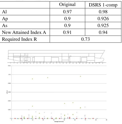
[image:7.595.41.288.201.452.2]With a goal of eradicating the risk associated with 2 com-partment damages to this space, the volume of foam af-forded to the system was set at 365 m3. The damage stabil-ity assessment was then re-conducted producing the results given in Table 12 and the updated risk profile in Fig. 12.
Table 12. Attained Index before and after DSRS
Original DSRS 1-comp
Al 0.97 0.98
Ap 0.9 0.926
As 0.9 0.925
New Attained Index A 0.91 0.94
Required Index R 0.73
Fig. 12. Small ROPAX new risk profile with DSRS 1-comp
The system has again proven here to be greatly effective in increasing the vessel’s safety level. Observation of the vessel’s updated risk profile shows that the risk stemming from two compartment damages to the stabiliser compart-ment has been eradicated. Furthermore, the risk associated with three compartment damages involving this space has been considerably reduced. In total the DSRS has achieved a risk reduction from 0.09 to 0.06 or 33%.
In case a second compartment is protected by the system with additional foam, the updated risk profile suggests that this should be the shaft alternator room and the fin stabiliser compartment. Assuming that the foam could be delivered to either of the given compartments if damaged, a new 2 DSRS compartment protection risk profile has been pre-pared and the new total risk has been estimated to 0.047 or 48% reduction from its original value.
CONCLUSIONS
The challenge faced by the maritime industry in the 21st century is to reduce drastically the loss of life in maritime transportation. The approach used in the 20th century has reached its plateau and a step change is required. The
au-thors argue that DSRS is the solution to this problem. This has been proven by the results presented herein. By com-bining expertise in ship damage stability and specialist knowledge in expanding foams, a non-intrusive cost-effective solution to the damage stability problem of ROPAX vessels has been identified that does not interfere with the existing characteristics of the vessel, its functional-ity or business model, enabling the vessel to remain com-petitive while being above all safer. The system can be easily installed in new and existing ships and its technology is proven and reliable.
REFERENCES
Allianz Global Corporate & Specialty SE (2015), Safety and Shipping Review 2015
https://www.allianz.com/v_1427190309000/media/press/do cument/other/Shipping-Review-2015.pdf (accessed 7 July 2016).
Boulougouris, E., Winnie, S. and Papanikolaou, A. (2016), “Assessment of survivability of surface combatants after damage in the sea environment”, J. Ship Production and Design 32/3, pp. 1–10.
Boulougouris, E.K., Papanikolaou, A. and Zaraphonitis G., (2004), “Optimisation of arrangements of Ro-Ro passenger ships with genetic algorithms”, Ship Technology Research 51/3, pp.99-105.
EC (2003), “DIRECTIVE 2003/25/EC of the European Parliament and of the Council on 14 April 2003 on specific stability requirements for ro-ro passenger ships”, Official J. of the European Union
EMSA (2015), EMSA/OP/10/2013 (EMSA 3), “Impact assessment compilation part 1; Impact assessment in ac-cordance with the EC IA”, Report No. 2015-1194, Rev. 3.
GOALDS (2009-2012). “Goal-based Damage Stability”, Project funded by the European Commission, FP7-DG Research, 233876.
IMO MSC.1/Circ. 1455 (2013), “Guidelines for the ap-proval of alternatives and equivalents as provided for in various IMO instruments”, 24 June 2013.
IMO MSC.Res.216(82) (2006), “Adoption of Amendments to the International Convention for the Safety Of Life At Sea, 1974, As Amended”, IMO, London
ROROPROB (2000-2003), “Probabilistic Rules-Based Optimal Design of Ro-Ro Passenger Ships”, FP5-DG Re-search, Contract Number G3RD-CT-2000-00030.
Vassalos, D. (2012), “Damage stability of passenger ships – Notions and truths”, STAB 2012, Athens pp.775-789.