City, University of London Institutional Repository
Citation
:
Mishra, J. K., Rahman, B. M. and Priye, V. (2016). Rectangular Array Multicore
Fiber Realizing Low Crosstalk Suitable for Next-Generation Short-Reach Optical
Interconnects With Low Misalignment Loss. IEEE Photonics Journal, 8(4), doi:
10.1109/JPHOT.2016.2591002
This is the published version of the paper.
This version of the publication may differ from the final published
version.
Permanent repository link:
http://openaccess.city.ac.uk/16550/
Link to published version
:
http://dx.doi.org/10.1109/JPHOT.2016.2591002
Copyright and reuse:
City Research Online aims to make research
outputs of City, University of London available to a wider audience.
Copyright and Moral Rights remain with the author(s) and/or copyright
holders. URLs from City Research Online may be freely distributed and
linked to.
Rectangular Array Multicore Fiber
Realizing Low Crosstalk Suitable for
Next-Generation Short-Reach Optical
Interconnects With Low
Misalignment Loss
Volume 8, Number 4, August 2016
Jitendra K. Mishra, Student Member, IEEE
B. M. A. Rahman, Fellow, IEEE
Vishnu Priye, Senior Member, IEEE
Misalignment Loss
Jitendra K. Mishra,1,2Student Member, IEEE,
B. M. A. Rahman,2Fellow, IEEE, and Vishnu Priye,1Senior Member, IEEE
1Department of Electronics Engineering, Indian School of Mines, Dhanbad 826 004, India 2
Department of Electrical and Electronic Engineering, City University London, London EC1V 0HB, U.K.
DOI: 10.1109/JPHOT.2016.2591002
1943-0655Ó2016 IEEE. Translations and content mining are permitted for academic research only. Personal use is also permitted, but republication/redistribution requires IEEE permission. See http://www.ieee.org/publications_standards/publications/rights/index.html for more information.
Manuscript received February 29, 2016; revised July 5, 2016; accepted July 6, 2016. Date of publica-tion July 18, 2016; date of current version July 26, 2016. This work was supported by the European Commission under the AREAS+ Erasmus Mundus mobility programme. Corresponding author: J. K. Mishra (e-mail: [email protected]).
Abstract:Toward the next-generation exa-scale short-reach optical interconnects (OIs) supporting large-capacity data transmission, a compact computer-compatible 8-core heterogeneous trench-assisted multicore fiber (TA-MCF) is proposed, in which cores are arranged in a rectangular array. To analyze the crosstalk (XT) between adjacent cores of TA-MCF OI, a rigorous full-vectorialH-field finite element method (FEM) and coupled power theory are applied. The impact of various trench design parameters on the mode-coupling coefficientCmn and the coupling length Lc is discussed in detail. An accurate explicit condition for the achievement of low XT in an 8-core heterogeneous TA-MCF OI is obtained through numerical simulations. A rigorous modal solution approach based on the computationally efficient FEM and the least squares boundary residual method is employed to analyze the coupling loss caused by the misalignment to a butt-coupled TA-MCF OI.
Index Terms:Optical interconnects (OIs), multicore fibers (MCFs), crosstalk (XT), coupling loss.
1. Introduction
to respond to the severe requirements of future short-reach optical transmission systems [4]. The space division multiplexing (SDM) technology realized by MCF is expected to overcome the imminent capacity crunch of short-reach OIs [5]. Besides increasing the transmission ca-pacity, MCF OI shows promise for coping with the cable size limitation in bandwidth intensive box-to-box, rack-to-rack, board-to-board and chip-to-chip interconnect applications which ne-cessitate high fiber count and high density cable [6]. Among other motivations, MCF with SDM is also less susceptible to optical power limitations imposed by the fiber non-linear ef-fects due to small power concentration per core [7]. However, suppression of intercore cross-talk (XT) is a primary concern in interconnection technology for efficient usage of MCF as OI [8]–[10].
Recently, various types of MCFs such as homogeneous MCFs [11], heterogeneous MCFs [12], and hole assisted MCFs [13] have been intensively investigated for high-capacity long-distance transmissions with the goal of suppressing the XT between the adjacent cores. Furthermore, it has also been proved that trench-assisted MCF (TA-MCF) realizes low inter-core XT with high inter-core density comparing to MCF with step-index profile [14]–[18]. Most of the results reported pertain to hexagonal or ring structures of MCF but their use as an OI is rela-tively less investigated. By keeping this in mind, a holey microstructured MCF based OI is re-cently proposed to realize low XT with dense core arrangement [4]. Furthermore, a ring structure of an 8-core homogeneous TA-MCF has been recently published for OI applications [19]. The hexagonal geometry of MCF can also support 2-D arrays of low cost vertical-cavity surface emitting lasers [20]. Although, hexagonal or ring arrangement of cores in MCF are more tightly packed but these are not compatible with number of parallel lanes in data buses re-quired in high performance computers, as well as on-chip integrated photonic systems. For such specific applications, rectangular array 8-core homogeneous MCF has been recently re-ported for OI applications [21], but homogeneous step-index MCF will result in a large XT be-tween adjacent cores [22]. Furthermore, research on 8-core heterogeneous MCF has also been published recently [6], [23]. So, in order to minimize the intercore XT, rectangular arrayed het-erogeneous TA-MCF can be a viable solution. However, to the best of our knowledge there has been no report yet on the rectangular arrayed heterogeneous TA-MCF for short reach OI applications.
The next daunting issue associated with the practical use of MCF as OI is the coupling of MCF to standard single-mode single core fibers (SCFs). So far, several fan-in fan-out (FIFO) schemes have been proposed, such as fiber bundled type [24], physical contact method [25], and coupling with lens optics [26]. Even though these proposals exhibited high coupling effi-ciency, their large size and mechanical instability would be concerns. In order to realize a pre-cise alignment between MCF and SCF, grating coupler array based FIFO [27] and V-groove type FIFO [28] have been recently reported. However, to obtain a low-loss coupling is particu-larly challenging due to the versatile core distribution geometries of MCFs. In this context, lami-nated polymer waveguide has been designed to allow efficient butt-coupling to the seven-core MCF [29]. However, it has also been suggested that the least squares boundary residual (LSBR) [30] method would be more efficient and accurate to use to determine the modal excita-tion coefficients at the butt-coupled juncexcita-tions. As far as we know, there has been no report ap-plying LSBR method to a butt-coupled MCF OI.
In this paper, an 8-core heterogeneous TA-MCF with rectangular arrangement is being pro-posed to meet the requirements of next-generation exa-scale short reach OIs and on-chip inte-grated photonic systems. The effects of quantitative and qualitative trench design parameters on the mode coupling coefficientCmnin the 8-core TA-MCF are investigated by using a rigorous
2. Theory
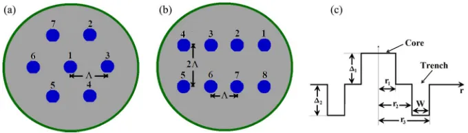
Fig. 1(a) shows a schematic cross section of hexagonally arranged 7-core MCF with a step-index profile. The design concept model of proposed MCF based OI, inside of which cores are arranged in rectangular arrays, as shown in Fig. 1(b) and the index profile of a core with trench, is shown in Fig. 1(c). All cores in TA-MCF OI are arranged with core to core pitchðÞ and distance between the two rows is 2. In Fig. 1(c), r1, r2, r3, 1, 2, and W represent the
core radius, the distance between the center of core and the inner edge of trench, the dis-tance between the center of core and the outer edge of trench, the relative refractive-index dif-ference between core and cladding, the relative refractive-index difdif-ference between trench and cladding, and the width of the trench layer, respectively.
2.1. Calculation of C
mnand XT Between TA-MCF OI Cores
In order to obtain the XT between two adjacent cores in TA-MCF, coupled power theory [10] is employed, but before that the value of mode coupling coefficientCmn between two
neighbor-ing cores of MCF OI with trench index profile is investigated first. The expression of couplneighbor-ing co-efficient between two cores is given as [32]
Cmn¼
!"0 þ1R 1
R þ1
1
N2N2 n
Em:Endxdy
2 ffiffiffiffiffiffiffiffiffiffiffiffiffiffiffiffiffiffiffiffiffiffiffiffiffiffiffiffiffiffiffiffiffiffiffiffiffiffiffiffiffiffiffiffiffiffiffiffiffiffiffiffiffiffiffiffiffiffiffiffiffiffiffiffiffiffiffiffiffiffi R þ1 1 R þ1
1 EmxH
myEmyHmx
dxdy s : ffiffiffiffiffiffiffiffiffiffiffiffiffiffiffiffiffiffiffiffiffiffiffiffiffiffiffiffiffiffiffiffiffiffiffiffiffiffiffiffiffiffiffiffiffiffiffiffiffiffiffiffiffiffiffiffiffiffiffiffiffiffiffiffiffiffiffi R þ1 1 R þ1
1 EnxH
nyEnyHnx
dxdy
s (1)
where!is an angular frequency of sinusoidally varying electromagnetic fields, and"0is the per-mittivity of free space. The pairm andn is either (1, 2) or (2, 1).E andH represent the electric and magnetic fields respectively. The refractive-index distribution in the entire coupled region is expressed as [32]
N2¼N12þN22n2 (2)
whereN1 and N2 represent the refractive index distribution of each core with trench index
pro-file, andn represents the refractive index distribution outside the cores respectively.N2N2
2 is
zero except inside the core 1, whileN2N2
1 is zero everywhere except inside core 2 [32].
A rigorous full-vectorialH-field finite element method (FEM) [31] is used in this work to calcu-late the mode coupling coefficientCmn. The FEM, based on the vector-H-Field formulation has
been established as one of the most accurate and numerically efficient approaches to obtain the modal field profiles and mode propagation constants of the arbitrarily-shaped waveguides with curved boundaries [31]. The full-vectorial formulation is based on the minimization of the fullH-field energy functional [31]
!2¼ R R
ðr HÞ:"1ðr HÞ þpðr:HÞðr:HÞ
dxdy R R
H:
Hdxdy (3) [image:5.594.128.468.59.156.2]whereHis the full-vectorial magnetic field, * denotes a complex conjugate and transpose,!2is
the eigenvalue (! being the angular frequency), p is a weighting factor for the penalty term to eliminate spurious modes, and"and
are the permittivity and permeability tensors, respectively. The mode coupling coefficients between the cores are used to calculate the power coupling coef-ficient [10]. Analytical approach based on exponential autocorrelation function and coupled power theory is employed to realize the accurate evaluation of intercore XT [10]. The power coupling coefficient based on an exponential autocorrelation function can be given as [10]hmn¼
2K2 mndc
1þ ðmndcÞ2
(4)
wherem,n represent the core m andn;Kmn is the average value of mode coupling coefficient
Cmn andCnm; dc is the correlation length; andmn is the propagation constant difference
be-tween the fundamental modes of cores m and n. Here, considering the bend-induced random perturbations that can occur while practical situation or during their usage as interconnects, the MCF is divided into finite segment of correlation length dc. In order to calculate the average
value of intercore XT,dc ¼0:05 m is used in this work, because this value agreed better with
the measured results [9]. The XT between two cores of TA-MCF OI over a lengthLis estimated by the coupled power theory as [10]
XT¼tanhðhmnLÞ (5)
wherehmnrepresents the average power coupling coefficient. The full-vectorial field obtained by
using theH-field based FEM is utilized to calculateCmnandhmnand, finally, the XT.
2.2. Calculation of Coupling Loss due to Misalignment
A powerful numerical approach, the LSBR [30] method is employed to analyze the power cou-pling between a MCF OI and a standard SCF. When butt-coucou-pling to a MCF OI, it is desirable that the beam divergence from the MCF is matched to the spot size of the standard SCF for pre-cise core alignment and low loss coupling. To undertake the analysis proposed, computationally efficient vector FEM [31] is used to obtain the modal field profiles over the cross section of the discontinuity plane. Subsequently, the LSBR method has been used here, which rigorously sat-isfies the continuity of the tangential electric and magnetic fields at the junction interface in a least-squares sense, to find the transmission and reflection coefficients at the butt-coupled junction interfaces. The LSBR method looks for a stationary solution to satisfy the continuity conditions by minimizing the error energy functionalJ, as given by [30]
J ¼ Z
EtIEtII 2
þ:Z02 HtIHtII 2d (6)
where Z0 is the free-space impedance; EtI, EtII, HtI, and HtII are the transverse components of
the electric and magnetic fields in side I and side II; and is the dimensionless weighting factor to balance the electric and magnetic components of the error functional J. The integration is carried out at the junction interfacebetween a straight MCF OI and a conventional SCF.
3. Numerical Results
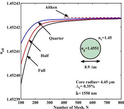
Before calculating theCmn values, numerical accuracy of theH-field based finite element modal
solutions is tested. The variations of the effective index,neff with the number of mesh divisions
Nused is shown in Fig. 2 for the fundamental mode of a SCF (see the inset of Fig. 2) designed with core refractive index ng¼1:4551, cladding refractive index nc¼1:45, and core diameter
directions. From the results depicted in Fig. 2, it can be inferred that, as the value ofNincreases,
neff first increases rapidly and then reaches a constant value asymptotically. From Fig. 2, it is
noted that when one-fold symmetry is used, shown by a red solid line, convergence is much faster than when the full structure is simulated, shown by a black solid line. However, it can be easily observed that as mesh refinement is carried out for two-fold symmetry, neff rapidly
con-verge to their exact solutions, as shown by a blue solid line. It should be noted that when a 100100 mesh is usedneffis accurate to fourth decimal place for two-fold symmetry, and the
accuracy is increased to 6th decimal place when mesh size is increased to 400400. A pow-erful Aitken’s extrapolation technique [33] can also be used to improve the solution accuracy of modal solution for this SCF structure. From three successive values ofneff with fixed geometric
mesh division ratio in both the transverse directions of SCF, final solutions can be extrapolated for a possible infinite mesh refinement as given as
neff1 ¼neffðrþ1Þ
neffðrþ1ÞneffðrÞ
2
neffðrþ1Þ2neffðrÞþneffðr1Þ: (7)
Aitken’s extrapolated values of n1eff for two-fold symmetry are plotted in Fig. 2 by a red-dashed line. Using (7), for instance, we calculate Aitken’s value from three neff values of 1.45241317,
1.45242148, and 1.45242332 forN¼100, 200, and 400, respectively. From these three values, the extrapolated more accurate value is obtained as 1.452424045. Fig. 2 clearly demonstrates the advantage of using Aitken’s extrapolation technique as shown by a red dashed line.
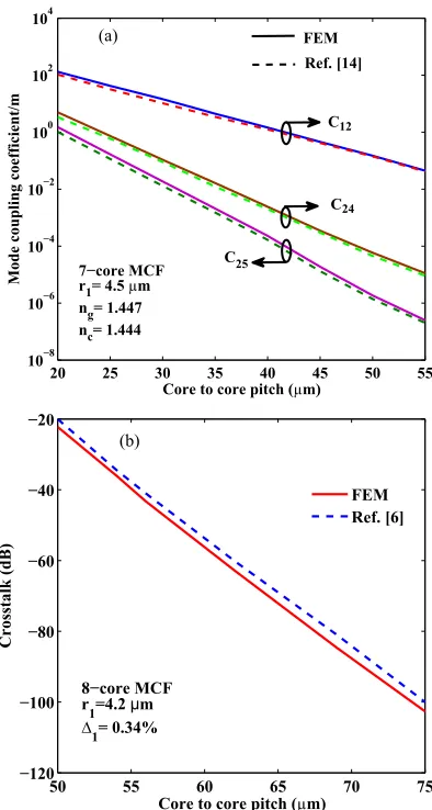
In order to demonstrate the accuracy of mode coupling coefficientCmn, numerical simulations
based on the rigorous vectorH-field FEM [31] is used to calculate the coupling coefficient be-tween adjacent and non-adjacent cores in 7-core MCF. The cross section of the homogeneous 7-core MCF with step index profile is shown in Fig. 1(a). For hexagonal MCF, individual cores are of radius r1¼4:5
m with refractive index of coreng ¼1:447 and cladding refractive indexnc ¼1:444, are taken, identical as in [14], to make a fair comparison. The operating wavelength of the optical signal is 1550 nm. The variations of theCmn between adjacent and non-adjacent
cores in hexagonal structure of 7-core MCF with core to core pitch are shown in Fig. 3(a). The dashed line represents the results of coupling coefficient between adjacent (C12) and
non-adjacent (C24 and C25) cores, which were reported in [14]. On the other hand, solid line
repre-sents the results of C12, C24, and C25 obtained by using the H-field based FEM [31]. It can be
observed from Fig. 3(a), the Cmn estimations based on the rigorous vector H-field FEM are in
[image:7.594.193.401.57.240.2]good agreement with the results reported in [14].
Fig. 2. Variations ofneffof the fundamental mode with the number of mesh in both the transverse
Afterwards, the accuracy of the analytical formula given in (5) for intercore XT calculation is tested. A rectangular array 8-core MCF is used here as a model to carry out this comparison. The schematic cross section of the homogeneous 8-core MCF with step index profile is shown in Fig. 1(b). The cladding index is taken as 1.45 and the relative refractive-index difference be-tween core and cladding is 0.34%, and the radii of the cores are 4.2
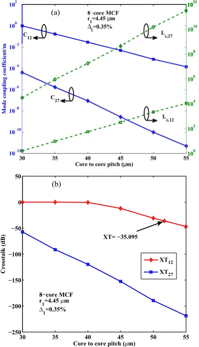
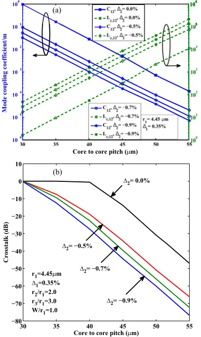
m. The index values and the radii are exactly the same as those in [6]. Variations of numerically simulated XT of step in-dex 8-core MCF with are shown in Fig. 3(b). In these simulations, the fiber length is taken as 100 m [6], and the wavelengthof the optical signal is 1550 nm. The red solid line represents the XT between core 1 and core 2, which is obtained by using (5) and optical field from the rig-orous vectorH-field FEM [31]. On the other hand, the blue dashed line relates the simulation re-sults reported in [6]. The comparison of these rere-sults shown in Fig. 3(b) clearly demonstrates that the results obtained by using the FEM field and (5) matches very well with the results of [6]. The discrepancy between the crosstalk values is very small, which proves the feasibility of ana-lytical formula used in this work.After validating the computational accuracy of the numerical approaches developed, detailed analyses of 8-core MCF are carried out. Fig. 4(a) shows variations of coupling coeffi-cients Cmn and coupling lengths Lc with core to core pitch for a step index 8-core MCF,
shown in Fig. 1(b). In this work, the radii of the cores are taken as 4.45
m and the relative [image:8.594.199.396.57.426.2]refractive-index difference between core and cladding as 0.35%, which are the structural param-eters reported in the fabricated homogeneous 8-core MCF [22]. The blue solid lines represent the results of Cmn. On the other hand, the green dotted lines represent the results of Lc. The
Cmn is determined by using the (1) and the accurate vectorH-field profile [31] to obtain the
spa-tial overlap of the electromagnetic fields of the fundamental modes for each core in isolation. It can be observed from Fig. 4(a) that the C12 (coupling coefficient between core 1 and core 2)
and C27 (coupling coefficient between core 2 and core 7) decreases with increase in . It can
also be noted that the coupling of power between core 2 and core 7 is much smaller compared to that between core 1 and core 2. The coupling lengthLc for complete mode power transfer
be-tween the adjacent core can be calculated from their propagation constants, by
Lc ¼=2ðeoÞ, wheree and o represents the propagation constants of the even and odd
supermodes, respectively. Moreover, it can be observed in Fig. 1(b), that the cores are arranged in a two different rows with linear array of four cores. Thus, coupling lengthLc can also be
cal-culated by using the coupled mode theory, i.e.,Lc ¼=2Cmn [32]. In this case,Lc calculated by
both the approaches agreed very well. The results plotted in Fig. 4(a) shows thatLc;12 andLc;27
increases with, this is because Lc is inversely proportion to the Cmn. It is also known thatLc
versus separation plotted in a semi-log scale yields a straight line, as shown here.
The Cmn and Lc serves as a measure for calculating the XT between the cores of MCF OI.
The target XT level can be set to −35 dB at 1550 nm for short reach MCF based OI
[image:9.594.193.396.60.413.2]transmission. Fig. 4(b) shows variations of XT calculated from (5) and by using accurateH-field profiles with core to core pitchfor a step index 8-core MCF. For the XT calculations, the fiber lengthLand the wavelengthof the optical signal are taken as 100 m [6] and 1550 nm, respec-tively. The red solid line represents the result of XT12 (XT between core 1 and core 2). On the
other hand, the blue solid line represents the result of XT27(XT between core 2 and core 7). It
can be observed from Fig. 4(b) that, as the value ofincreases, XT12has very small change at
first and then decreases rapidly. On the other hand, XT27 decreases rapidly with increasing .
Fig. 4(b) clearly illustrates that the distance between the cores in the same row should be 51.7
m to achieve the target XT level of −35 dB. From the results depicted in Fig. 4(b), it can be concluded that the XT between core 2 and core 7 is very small and can be ignored for further simulation.Earlier, trench-assisted structure was reported [14]–[16] as shown in Fig. 1(c) and next this is considered with the index profile given to suppress the power coupling between the cores of MCF. Fig. 5(a) illustrates the numerically simulatedC12 and Lc;12 of homogeneous TA-MCF OI
with the at a optical wavelength of 1550 nm where the relative trench position r2=r1 and the
relative trench width W=r1are taken as 2.0 and 1.0, respectively and the core radiusr1 and
rela-tive refracrela-tive-index difference between core and cladding are fixed at 4.45
m and 0.35%, re-spectively. The variations of C12 and Lc;12 are simulated for 2¼ 0:5%, −0.7%, and −0.9%.TheC12 and Lc;12 for normal step-index 8-core MCF structure is also included for comparison,
which can be regarded as trench-assisted structure with2¼0%, shown in Fig. 1(c). The blue Fig. 5. (a) Variations of mode-coupling coefficient and coupling length with the core to core pitch for
an 8-core TA-MCF for different 2 values, when r2=r1¼2:0, r3=r1¼3:0, and W=r1¼1:0.
[image:10.594.192.395.60.401.2]get the minimum C12 and maximum Lc;12. This shows the trench optically isolates the cores,
reduces XT and increases theLc.
Fig. 5(b) shows the variations of XT with for 8-core homogeneous TA-MCF OI for
2¼ 0:5%, −0.7%, and −0.9%. In order to compare the XT characteristics simulation results
of step-index 8-core MCF structure is also included (shown here as 2¼0%). The
homoge-neous TA-MCF OI parameters are same as that in Fig. 5(a) and XT12 is obtained by using
(5). The plot shows that for a given 2, XT12 decreases with increase in . As can be seen
from Fig. 5(b) that XT12 decreases with increasing the value of low-index trench2. Moreover,
for sameof 45
m and at the condition2¼ 0:5%, XT12in TA-MCF OI is 20 dB smaller ascompared to step-index counterpart. It can be noted from Fig. 5(b) that the XT12 reduces by
more than 10 dB if low-index trench 2¼ 0:9% rather than 2¼ 0:5% is selected at of
45
m. Fig. 5(b) clearly illustrate that the requiredfor a homogeneous TA-MCF OI is 43.7m if the trench parameter2is fixed at−0.7%, corresponding to the target XT level of −35 dB. Onthe other hand, the requiredfor a homogeneous TA-MCF OI is 42.3
m if the trench parame-ter 2 is fixed at−0.9%. This value is 9.4 m lower than the required for step index 8-coreMCF. However, the trench parameter2 of−0.7% might be the limit for TA-MCF OI fabrication
[16]. From this comparison, we can find clearly that the TA-MCF OI gives rise to better XT per-formance and arrangement can be more compact.
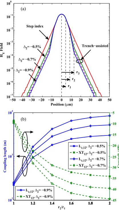
To clearly demonstrate the effect of trench onCmn,Lc and XT, dominantHY field of the
funda-mental quasi-TE,H11y mode for 8-core step index and TA-MCF is plotted in Fig. 6(a). A rigorous vector H-field FEM [31] is employed to obtain the field distributions of trench index core for
2¼0%, −0.5%, −0.7% and −0.9%, as shown in Fig. 1(c). It can be observed from Fig. 6(a)
that the deployment of trench layer around each core can depress the field distributions, far away from the core. Variation of the modal field is plotted in a semi-log scale. Here outside the core (beyondr1) field varies exponentially, which is shown by a line with a constant slope when
semi-log scale is used. The slopes betweenr1 tor2and beyond r3are the same as local index
in these regions were same. However, when refractive index in the trench region, shown here between r2 and r3 is reduced, the slope of the field variation also shows faster field reduction.
Moreover, field reduces faster between distance r2r3 (where trench is located) if low-index
trench2is higher. Therefore, the spatial overlap of the electromagnetic field between two
adja-cent cores of TA-MCF OI will be small, resulting Cmn and XT will reduce even if the is very
small. It is shown in Fig. 6(a), as low-index trench2 is increased from−0.5% to −0.9%, a
fur-ther reduction ofCmnand XT is possible.
Afterwards, in order to investigate the influence of the location of trench onLc and XT
charac-teristics, numerical simulations based on rigorous vectorH-field FEM is illustrated in Fig. 6(b). Here, the fixed values forr1,1,, andW=r1, are assumed as 4.45
m, 0.35%, 45m, and 1.0,respectively andr2=r1varied from 1.0 to 2.0 to study the impact of the location of the trench layer.
The simulations are carried out for 2¼ 0:5%, −0.7% and −0.9%. It can be observed in
Fig. 6(b), that theLc increases withr2=r1and for a given location of the trench with high value of
low-index trench2. Moreover, XT12of an 8-core homogeneous TA-MCF OI decreases with
in-creasingr2=r1and for a given location of trench with high value of low-index trench2. It can be
noticed that, whenis fixed at 45
m, it is possible to obtain XT12less than−35 dB under twoconditions—i) r2=r1¼1:6, 2¼ 0:7%, ii) r2=r1¼1:4, 2¼ 0:9%. Although the low-index
regular outside vapor deposition (OVD) and vapor axial deposition (VAD) processes, the 2
value can be limited to be around−0.7% [16]. Therefore, to find out the optimized arrangement of trench location with reducedand to make sure the trench is not overlapping with the adja-cent trenches, we can increase the value ofr2=r1to 2.0.
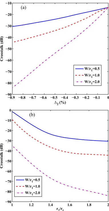
Fig. 7(a) shows the variations of XT with the2 for an 8-core TA-MCF OI for different W=r1
values. Here, the value for r1, 1, , and r2=r1 are fixed and assumed as 4.45
m, 0.35%,45
m, and 2.0, respectively and 2 is varied from 0% to −0.9% to demonstrate the effectof trench width on XT properties. The numerical results of a XT for 8-core TA-MCF OI are simu-lated based on (5) and using accurateH-field profiles [31]. It can be observed from Fig. 7(a) that the XT between core 1 and core 2 of an 8-core homogeneous TA-MCF OI decreases with in-creasing the value of low-index trench2 for a given width of the trench layer. Moreover, the
XT can be drastically reduced by employing larger width of the trench. It can be noted from Fig. 7(a) that, with2¼ 0:7%, and 2¼45
m, XT reduces by more than 10 dB if W=r1in-creased from 0.5 to 1.0. On the other hand, for the same value of 2¼ 0:7%, XT reduces
by more than 28 dB if W=r1 is increased from 1.0 to 2.0. Moreover, if 2 is fixed at −0.9%,
we can get XT of less than−80 dB forW=r1¼2:0 at¼45
m.Fig. 7(b) shows the variations of XT with ther2=r1for an 8-core TA-MCF OI for differentW=r1.
Here, the value for r1;1;2; are fixed at 4.45
m, 0.35%, −0.9%, 45 m, respectively andr2=r1value is changed from 1.0 to 2.0 to demonstrate the effect of trench width on XT properties. Fig. 6. (a)HY field of the fundamental mode for 8-core step index and TA-MCF. (b) Variation of
[image:12.594.192.400.59.424.2]From the results depicted in Fig. 7(b), it can be inferred that the XT for an 8-core homogeneous TA-MCF OI decreases with increasing the valuer2=r1. Moreover, the XT can be drastically
im-proved by means of sufficiently large trench width. It can be noted from Fig. 7(b) that, with
r2=r1¼2:0, and¼45
m, XT reduces by more than 12 dB ifW=r1 increased from 0.5 to 1.0.On the other hand, for the same value ofr2=r1¼2:0, XT reduces by more than 39 dB if W=r1is
increased from 1.0 to 2.0.
Afterwards, in order to design a more compact arrangement an 8-core heterogeneous TA-MCF OI is considered, where the delta of the core 2 is changed by 2% [see Fig. 1(b)]. Fig. 8 illustrates the variations of XT with for an 8-core heterogeneous TA-MCF OI for
2¼ 0:7%,r2=r1¼1:3,r3=r1¼2:0, andW=r1¼0:7. In order to compare the XT characteristics
simulation results of an 8-core homogeneous TA-MCF OI are also included. The homogeneous TA-MCF OI parameters are same as that in Fig. 5(b). It can be observed from Fig. 8 that the XT for heterogeneous TA-MCF OI decreases with increase inand exhibits very low XT compared to 8-core homogeneous TA-MCF. It can also be noted that for same of 35
m and with2¼ 0:7%, XT in heterogeneous TA-MCF OI is 63 dB smaller as compared to homogeneous
counterpart. Fig. 8 clearly illustrate that the required for a heterogeneous step-index MCF OI is 25.3
m, corresponding to the target XT level of−35 dB. On the other hand, the required for a heterogeneous TA-MCF OI is 22.1m if the trench parameter2 is fixed at −0.7%. ThisFig. 7. (a) Variations of XT with the2for an 8-core TA-MCF OI for different widths of the trench.
[image:13.594.202.393.57.427.2]value is 21.6
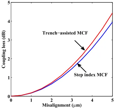
m lower than therequired for a homogeneous TA-MCF; therefore, the core ar-rangement can be more compact than MCF reported recently [6], [19], [23] with high density core for OI applications.Whenever we couple a MCF to a standard SCF, it may not be perfectly aligned and effect of possible misalignment is studied next. Fig. 9 illustrates the variations of coupling loss caused by the misalignment for step index MCF and TA-MCF OI. Here, we fixed the value for r1, 1,2,
r2=r1,r3=r1, andW=r1, which are assumed as 4.45
m, 0.35%,−0.7%, 1.3, 2.0, and 0.7,respec-tively. Here, we still assume 2¼0%, shown in Fig. 1(c) for step index MCF. Simulations are
based on full-vectorial modalH-field [31] and the LSBR [30] approach to accurately analyze the coupling loss on small variations in the facet’s position along the optical axis of step index MCF and TA-MCF OI. In Fig. 9 the blue solid line represent the coupling loss for step index MCF and the red solid line represent the coupling loss for TA-MCF OI. It can be noticed that the 3 dB coupling loss for TA-MCF and step index MCF is obtained at the misalignment of 4.1
m and 4.3 m, respectively. As it can be observed in Fig. 9, coupling loss increases exponentially with misalignment for the both structure, 2¼0% and 2¼ 0:7%. However, for TA-MCF [image:14.594.200.393.57.238.2]ð2¼ 0:7%Þ, the coupling loss is only slightly higher compared to step index MCF Fig. 8. Variations of XT with the core-to-core pitch for an 8-core heterogeneous TA-MCF when
2¼ 0:7%,r2=r1¼1:3,r3=r1¼2:0, andW=r1¼0:7.
[image:14.594.202.391.288.467.2]next generation exa-scale high performance computers and silicon photonic transceiver chips. A rigorous full-vectorialH-field FEM is used to calculate accurate modal field to obtain the cou-pling coefficientCmn and coupling lengthLc between the adjacent cores as a function of the
im-portant TA-MCF design parameters. The critical issue of crosstalk in the step index MCF and TA-MCF is quantified using the coupled power theory. In order to establish accuracy of this approach used here, comparisons are also made with the earlier reported results of 7-core hexagonal MCF and 8-core homogeneous MCF with same structural parameters. To design a TA-MCF OI, there are six important parameters that determine the profile—r1,1, 2,r2=r1, ,
and W=r1. The impact of various TA-MCF OI design parameters on Cmn, Lc, and XT are
thor-oughly investigated. Although, the low-index trench2¼ 0:9% is preferable for XT reduction
but in the view point of fabrication using regular OVD and VAD processes,2¼ 0:7% is
ap-proximately suitable value. Through simulations, we have confirmed that OI based on 8-core heterogeneous TA-MCF can greatly reduce the crosstalk with more compact arrangement by adjusting the trench parameters. It is shown here that the required for an 8-core homoge-neous TA-MCF is 43.7
m, corresponding to the target XT level of −35 dB. On the other hand, the required in heterogeneous TA-MCF OI can be reduced to 22.1m, if the parameters are fixed asr2=r1¼1:3,W=r1¼0:7, and2¼ 0:7%.Subsequently, the vector FEM is employed to obtain the modal propagation properties and the LSBR method is used to calculate the coupling loss caused by the misalignment between TA-MCF OI and SCF. The results are compared with the coupling loss between step index MCF and SCF to ascertain the trade off incurred by adding a trench layer to suit next generation OI specifications. The deployment of trench layer around each core increases the modal field con-finement. Due to this fact, the spot size decreases and the coupling loss in TA-MCF OI is slightly higher than that of a step index MCF. This marginal increase in coupling loss can be traded off with drastic XT reduction in heterogeneous TA-MCF OI. The reported results clearly substantiate the potential of this technology for use in designing future practical OIs and silicon photonic transceivers.
References
[1] M. A. Taubenblatt, “Optical interconnects for high-performance computing,” J. Lightw. Technol., vol. 30, no. 4, pp. 448–457, Feb. 2012.
[2] S. Abrateet al.,“10Gbps POF ribbon transmission for optical interconnects,”inProc. IEEE Photon. Conf., Arlington, VA, USA, Oct. 9–13, 2011, pp. 230–231.
[3] J. A. Kashet al.,“Optical interconnects in future servers,”presented at the Opt. Fiber Commun. Conf./Nat. Fiber Optic Eng. Conf., Los Angeles, CA, USA, Mar. 6–10, 2011, Paper OWQ1.
[4] V. Francois and F. Laramee, “Multicore fiber optimization for application to chip-to-chip optical interconnects,”
J. Lightw. Technol., vol. 31, no. 24, pp. 4022–4028, Dec. 2013.
[5] J. K. Mishra, V. Priye, and B. M. A. Rahman,“Error probability performance of a short-reach multicore fiber optical interconnect transmission system,”Opt. Lett., vol. 40, no. 19, pp. 4556–4559, Oct. 2015.
[6] M. J. Li, B. Hoover, V. N. Nazarov, and D. L. Butler,“Multicore fiber for optical interconnect applications,”in Proc. 17th Opto-Electron. Commun. Conf., Busan, South Korea, Jul. 2–6, 2012, pp. 564–565.
[7] T. Morioka, Y. Awaji, R. Ryf, P. Winzer, D. Richardson, and F. Poletti,“Enhancing optical communications with brand new fibers,”IEEE Commun. Mag., vol. 50, no. 2, pp. s31–s42, Feb. 2012.
[8] S. Matsuoet al.,“Crosstalk behavior of multi-core fiber with structural parameter drift in longitudinal direction,”IEICE Electron. Exp., vol. 8, no. 17, pp. 1419–1424, Sep. 2011.
[10] M. Koshiba, K. Saitoh, K. Takenaga, and S. Matsuo,“Analytical expression of average power-coupling coefficients for estimating intercore crosstalk in multicore fibers,”IEEE Photon. J., vol. 4, no. 5, pp. 1987–1995, Oct. 2012. [11] K. Takenaga, S. Tanigawa, N. Guan, S. Matsuo, K. Saitoh, and M. Koshiba, “Reduction of crosstalk by
quasi-homogeneous solid multi-core fiber,”presented at the Opt. Fiber Commun. Conf., San Diego, CA, USA, Mar. 21–25, 2010, Paper OWK7.
[12] M. Koshiba, K. Saitoh, and Y. Kokubun,“Heterogeneous multi-core fibers: Proposal and design principle,”IEICE Electron. Exp., vol. 6, no. 2, pp. 98–103, Jan. 2009.
[13] K. Saitoh, T. Matsui, T. Sakamoto, M. Koshiba, and S. Tomita, “Multi-core hole-assisted fibers for high core density space division multiplexing,”inProc. 15th Opto-Electron. Commun. Conf., Sapporo, Japan, Jul. 5–9, 2010, pp. 164–165.
[14] S. Zheng, G. Ren, Z. Lin, and S. Jian,“Mode-coupling analysis and trench design for large-mode-area low-cross-talk multicore fiber,”Appl. Opt., vol. 52, no. 19, pp. 4541–4548, Jul. 2013.
[15] J. Tu, K. Saitoh, M. Koshiba, K. Takenaga, and S. Matsuo,“Design and analysis of large-effective-area heterogeneous trench-assisted multi-core fiber,”Opt. Exp., vol. 20, no. 14, pp. 15157–15170, Jul. 2012.
[16] K. Saitoh, M. Koshiba, K. Takenaga, and S. Matsuo,“Crosstalk and core density in uncoupled multicore fibers,”
IEEE Photon. Technol. Lett., vol. 24, no. 21, pp. 1898–1901, Nov. 2012.
[17] J. Tu, K. Long, and K. Saitoh,“An efficient core selection method for heterogeneous trench-assisted multi-core fiber,”
IEEE Photon. Technol. Lett., vol. 28, no. 7, pp. 810–813, Apr. 2016.
[18] B. Liet al., “The role of effective area in the design of weakly coupled MCF: Optimization guidance and OSNR improvement,”IEEE J. Sel. Topics Quantum Electron., vol. 22, no. 2, Mar./Apr. 2016, Art. no. 4401407.
[19] T. Hayashi et al., “125-m-Cladding 8-core multi-core fiber realizing ultra-high-density cable suitable for O-band short-reach optical interconnects,”presented at the Opt. Fiber Commun. Conf., Los Angeles, CA, USA, Mar. 22–26, 2015, Paper Th5C.6.
[20] B. G. Leeet al.,“End-to-end multicore multimode fiber optic link operating up to 120 Gb/s,”J. Lightw. Technol., vol. 30, no. 6, pp. 886–892, Mar. 2012.
[21] D. L. Butleret al.,“Multicore optical fiber and connectors for high bandwidth density, short reach optical links,”in
Proc. IEEE Opt. Interconnects Conf., Santa Fe, NM, USA, May 5–8, 2013, pp. 9–10.
[22] T. Hayashi, T. Nakanishi, T. Sasaki, K. Saitoh, and M. Koshiba, “Dependence of crosstalk increase due to tight bend on core layout of multi-core fiber,”presented at the Opt. Fiber Commun. Conf., San Francisco, CA, USA, Mar. 9–13, 2014, Paper W4D.4.
[23] J. K. Mishra and V. Priye,“Design of low crosstalk and bend insensitive optical interconnect using rectangular array multicore fiber,”Opt. Commun., vol. 331, pp. 272–277, Nov. 2014.
[24] K. Watanabe, T. Saito, K. Imamura, and M. Shiino,“Development of fiber bundle type fan-out for multicore fiber,”in
Proc. 17th Opto-Electron. Commun. Conf., Busan, South Korea, Jul. 2–6, 2012, pp. 475–476.
[25] Y. Abe, K. Shikama, S. Yanagi, and T. Takahashi,“Physical-contact-type fan-out device for multicore fibre,”Electron. Lett., vol. 49, no. 11, pp. 711–712, May 2013.
[26] Y. Tottori, T. Kobayashi, and M. Watanabe,“Low loss optical connection module for seven-core multicore fiber and seven single-mode fibers,”IEEE Photon. Technol. Lett., vol. 24, no. 21, pp. 1926–1928, Nov. 2012.
[27] Y. Ding, F. Ye, C. Peucheret, H. Ou, Y. Miyamoto, and T. Morioka,“On-chip grating coupler array on the SOI platform for fan-in/fan-out of MCFs with low insertion loss and crosstalk,”Opt. Exp., vol. 23, no. 3, pp. 3292–3298, Feb. 2015. [28] Y. Abe, K. Shikama, H. Ono, S. Yanagi, and T. Takahashi,“Fan-in/fan-out device employing v-groove substrate for
multicore fibre,”Electron. Lett., vol. 51, no. 17, pp. 1347–1348, Aug. 2015.
[29] T. Watanabe, M. Hikita, and Y. Kokubun,“Laminated polymer waveguide fan-out device for uncoupled multi-core fibers,”Opt. Exp., vol. 20, no. 24, pp. 26317–26325, Nov. 2012.
[30] B. M. A. Rahman and J. B. Davies,“Analysis of optical waveguide discontinuities,”J. Lightw. Technol., vol. 6, no. 1, pp. 52–57, Jan. 1988.
[31] B. M. A. Rahman and J. B. Davies,“Finite-element solution of integrated optical waveguides,”J. Lightw. Technol., vol. 2, no. 5, pp. 682–688, Oct. 1984.
[32] K. Okamoto,Fundamentals of Optical Waveguides. Tokyo, Japan: Corona, 1992, ch. 4.