This is a repository copy of
Enhancement of collisionless shock ion acceleration by
electrostatic ion two-stream instability in the upstream plasma
.
White Rose Research Online URL for this paper:
http://eprints.whiterose.ac.uk/145255/
Version: Published Version
Article:
Kumar, Rajesh, Sakawa, Youichi, Döhl, Leonard N.K. et al. (2 more authors) (2019)
Enhancement of collisionless shock ion acceleration by electrostatic ion two-stream
instability in the upstream plasma. Physical Review Accelerators and Beams. 043401.
ISSN 2469-9888
https://doi.org/10.1103/PhysRevAccelBeams.22.043401
[email protected] https://eprints.whiterose.ac.uk/ Reuse
This article is distributed under the terms of the Creative Commons Attribution (CC BY) licence. This licence allows you to distribute, remix, tweak, and build upon the work, even commercially, as long as you credit the authors for the original work. More information and the full terms of the licence here:
https://creativecommons.org/licenses/
Takedown
If you consider content in White Rose Research Online to be in breach of UK law, please notify us by
Enhancement of collisionless shock ion acceleration by electrostatic ion
two-stream instability in the upstream plasma
Rajesh Kumar,1,*Youichi Sakawa,2Leonard N. K. Döhl,3Nigel Woolsey,3and Alessio Morace2
1
Graduate School of Science, Osaka University, Toyonaka, Osaka 560-0043, Japan 2
Institute of Laser Engineering, Osaka University, Suita, Osaka 565-0871, Japan 3
Department of Physics, University of York, Heslington, York YO10-5DD, United Kingdom (Received 1 October 2018; published 5 April 2019)
Ion acceleration in electrostatic collisionless shocks is driven by the interaction of the high-power laser with specially tailored near-relativistic critical density plasma. 2D EPOCH particle-in-cell simulations show that the ion acceleration is dependent on the target material used. In materials with low charge-to-mass ratiohZ=Ai, proton beams with high flux and low energy spread are generated. In multi-ion plasmas the ions with differenthZ=Aiacquire different velocities under a non-oscillating component of electrostatic field in the upstream region. This relative drift between the protons (hZ=Ai ¼1) and the lowerhZ=Aiions
leads to the excitation of electrostatic ion two-stream instability. This in turn generates a low-velocity component in the upstream expanding protons. The velocity distribution of the upstream expanding protons is further broadened toward the higher velocity by the electrostatic ion two-stream instability between reflected protons, which results in large number of protons being accelerated by the shock.
DOI:10.1103/PhysRevAccelBeams.22.043401
I. INTRODUCTION
The development of high-intensity laser systems has opened a new era for laser-driven ions acceleration and there are several promising mechanisms for laser-driven ion acceleration. The energetic ion beams driven by laser-plasma interaction have many potential applications such as accelerator physics, cancer therapy, proton radiography,
and inertial confinement fusion[1–3]. However, producing
a proton beam with high energy, high flux, and low energy-spread proved to be the major challenge for practical
applications [4,5]. Several mechanisms have been
studied for laser-driven acceleration. At present, the most widely understood mechanism is Target Normal Sheath
Acceleration (TNSA). This mechanism [6] and a related
radiation-pressure hybrid-scheme [7]can drive protons to
energies approaching 100 MeV. Alternative acceleration schemes, such as radiation-pressure acceleration that can achieve monoenergetic and higher energy suitable for applications impose strict and challenging conditions in experiments, such as the target thickness and laser contrast
[8–10]. We describe a method to circumvent such constraints
whilst providing methods to achieve higher ion energies.
Collisionless shock acceleration (CSA) has been
pro-posed separately by Denavit [11] and Silva [12], with a
detailed theoretical investigation complemented by Fiuza
[13]. These studies suggest that a special near-critical
density profile, Ncr, is important in order to control the
sheath electric field, ETNSA, at the plasma-vacuum
inter-face. This in turn affects the ion spectrum in CSA. The
ETNSAamplitude can be reduced by using an exponentially
decreasing density profile on the rear-side of the target[14],
finally resulting in a quasimonoenergetic distribution for the CSA ions. CSA experiments using a linearly polarized
CO2 laser with near-Ncr gas-jet targets produced 20 MeV
proton beam [15]. A number of experiments have been
carried out over the last few years to understand and
characterize ion acceleration via CSA[16–21]. One aspect
of CSA that is currently not well understood for accel-erating mono-energetic ions to high energies is the effect of the target material used.
In this paper we used the EPOCH particle-in-cell (PIC)
open source code[22]to study the generation of electrostatic
(ES) collisionless shocks and proton acceleration from shocks formed in plasmas of different material composition. Our results show that a low average charge-to-mass ratio
(hZ=Ai) plasma produces a higher proton beam flux with a
higher laser-to-proton energy conversion efficiency, and these differences become smaller at higher laser intensities. In the plasma with multi-ion species the ions with lower
hZ=Ai compared to the protons (with hZ=Ai ¼1) gain
different velocities. This results in difference between
relative drift velocities of the protons and lowerhZ=Aiions
in the upstream region of the shock. This leads to the *[email protected]
excitation of an electrostatic ion two-stream instability (EITI)
[23], which in turn enhances the number of the
shock-accelerated protons[24]. To our best knowledge, most of the
previous work has focused on shock formation[25–27]and
ion heating[28–30]. This paper is the first investigation on
the material (orhZ=Ai) dependence of EITI on CSA.
II. SIMULATIONS
We used 2D EPOCH simulations to investigate proton acceleration via CSA mechanism by modeling plasmas with different multi-ion compositions used commonly in experiments as target materials. The simulation box is
300×6 μm in size and composed of 9000×180 cells
along the x- and y-axis respectively. Each cell contains
24–30 particles depending upon the material being studied.
Open and periodic boundary conditions are used along the x- andy-axis respectively for both fields and particles.
The laser pulse and target in the PIC simulations use the parameters achievable at the Institute of Laser Engineering, Osaka University. An experiment would use the high intensity LFEX for the main interaction and the Gekko XII laser to preionize the target rear surface and create the necessary density profiles for CSA mechanism. The high intensity beam irradiated on the target front surface is linearly p-polarized with a temporal Gaussian profile of 1.5 ps full-width at half-maximum and peak intensity of
1.4×10¹⁹ W=cm2 (a
0¼3.35). The target consists of a
tailored density profile increasing exponentially for30μm
with5μm density scale length atNcron laser side, a5μm
region of constant density at the relativistic critical density
a0Ncr, and an exponentially decreasing density with30μm
scale-length on the rear extending for 125μm. The initial
density profile is shown in Fig. 1(a), t¼0. The
corre-sponding ion densities are configured to ensure quasineu-trality. The density profile and laser parameters are the same for all materials. The different material compositions
and associatedhZ=Aiused in this study are summarized in
TableI. The simulations are timed to reach peak irradiance
at 1.5 ps and have an initial electron and ion temperature
of Te ¼Ti¼500eV.
A. Collisionless shock formation
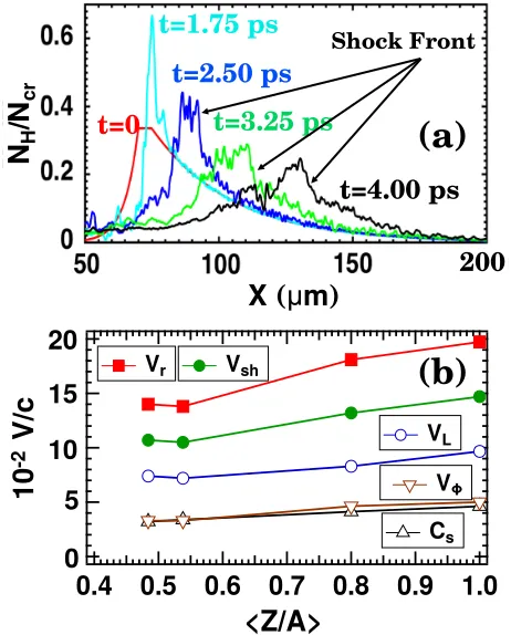
Figure1(a)shows the temporal evolution ofNH=Ncr in
C2H3Cl for a number of times after the peak of the laser
pulse, which enter the particle grid at 1.5 ps. During the
time from t¼0 to t¼1.75ps the laser interaction with
plasma results in uniform electron heating viaJ×B [31].
This compresses the plasma in front of the exponentially decreasing density on the rear target side, as shown by the
peak in the density profile in Fig. 1(a). As time evolves,
the density on the target rear side is expanding, resulting in the formation of the ES collisionless shock. The shock
propagates at velocity Vsh in the forward direction. The
exponentially decreasing density profile in the upstream
plasma, the region ahead of the shock results in a uniform
ES sheath field ahead of the shock, ETNSA¼Te=eLg,
where Te is the upstream electron temperature, e is the
electric charge, andLgis the exponentially decreasing
rear-side scale-length [14]. This ETNSA field gives a uniform
velocityV0 to the upstream expanding protons.
For an ES collisionless shock to accelerate protons by
ion reflection the ES potentialϕat the shock must satisfy
the relation Zeϕ≥12AmpðVsh−V0Þ
2, where
Z¼A¼1
for protons, andmpis the proton mass[32]. Shock reflected
protons have a velocity Vr¼2Vsh−V0. ϕ can be
esti-mated by subtracting the non-oscillating component of
ETNSAfrom the overall ES field (Ex) and integrating along
the x-axis, ϕ¼Rx
∞ðEx−ETNSAÞdx. At t¼2.5ps, ϕ is large, as a result, acceleration of upstream protons via FIG. 1. (a) The temporal evolution ofNH=Ncr in C2H3Cl at t¼0, 1.75, 2.50, 3.25, and 4.00 ps. (b)hZ=Aidependence of the ion acoustic speedCs, the lower thresholdVL, the shock speed
Vsh,Vϕ¼
ffiffiffiffiffiffiffiffiffiffiffiffiffiffiffiffiffi
2eϕ=mp
p , and the velocity of the shock reflected
protonsVr att¼4.0ps.
TABLE I. The charge-to-mass ratio for different targets. Note, all ions are fully ionized except chlorine which hasZCl¼15.
Material C2H3Cl CH He
3H Hydrogen
hZ=Ai 0.4839 0.5385 0.8 1
hZi 30 7 4 1
hAi 62 13 5 1
KUMAR, SAKAWA, DÖHL, WOOLSEY, and MORACE PHYS. REV. ACCEL. BEAMS 22,043401 (2019)
[image:3.612.322.553.45.332.2] [image:3.612.315.560.656.715.2]shock reflection occurs. By t¼4.0ps, ϕ is gradually dissipating and reflection of protons becomes negligible.
Figure1(b)compares thehZ=Aidependence of a number
of velocities relative to the speed of light, c. Here Vϕ¼
ffiffiffiffiffiffiffiffiffiffiffiffiffiffiffiffiffi
2eϕ=mp
p
andVL¼Vsh−Vϕ is the lower threshold for
the proton reflection. The velocitiesVr,Vsh,VL,Vϕand the
ion acoustic speedCSshow a general increase withhZ=Ai.
The increasing velocities result from a ffiffiffiffiffiffiffiffiffi
Z=A
p
dependence
in the hole-boring velocityVHB¼c
ffiffiffiffiffiffiffiffiffiffiffiffiffiffiffiffiffiffiffiffi
Z
2A me
mp
Ncr
Nea
2 0
q
with the
nonrelativistic limit[33]. This is a good approximation for
the lowa0used. Heremeis the electron mass,a0andNeare
the same for all the materials. The shock front moves
forward at velocity Vsh, which is powered by the
laser-driven hole boring process at the target front. As there is
a rear surface density drop,Vshincreases in time. Protons
with velocities V0 that lie between VL and Vsh are
accelerated via shock reflection.
A 2D-relativistic MaxwellianfðEÞ∝Eexpð−E=TeÞ is
used for the electron energy spectrum in the upstream
region. For all materials,Te∼2.0MeV. This implies that
the ion acoustic speed is given by Cs¼
ffiffiffiffiffiffiffiffiffiffiffiffiffiffiffiffiffiffiffiffi
ZTe=Amp
p
is
only a function of hZ=Aias shown in Fig. 1(b).
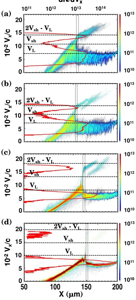
Figures2(a)–2(d)show the proton phase-space at 4.0 ps
for each of the materials shown in TableI. The red solid line
overlaid on each of the plots corresponds to the proton velocity distribution in the upstream region ahead of the shock front. This is integrated from the velocities within the vertical box in the phase-space plots, which spans across a
range ofΔx¼3μm. The horizontal lines are the material
dependent velocities Vr,Vsh, andVL. Protons that satisfy
the inequality VL ≤V0≤Vsh are shock reflected. For
target materials with lower hZ=Ai, such as C2H3Cl and
CH, a significantly larger number of protons satisfy this
inequality when compared to He3H and H. As a result, a
larger number of protons are shock accelerated. This is
deduced by comparing Figs. 2(a)and2(b)with Figs.2(c)
and 2(d). The proton velocity distribution is broader at
lowerhZ=Aidue to the presence of the lowerhZ=Aiions.
A broad velocity distribution results in a variation of the Mach number (M). To account for this we define
M¼ ðVsh−VmeanÞ=Cs, whereVmeanis a mean value ofV0
in the distribution. In our calculations, we obtain M¼
1.6–1.7 for all materials. This is in agreement with the
critical Mach number (Mcr¼1.6), which has been
pre-viously validated in PIC simulations for linearly polarized
laser pulse[11,13]. Therefore, the particle acceleration, and
thus shock dissipation, is expected when the ions are being reflected. The maximum velocity of the reflected protons
from the shock front is expected to reach 2Vsh−VL.
Simulations show that the velocity distribution just ahead of the shock peaks around this maximum velocity. In the
upstream plasma, protons with higherhZ=Aiare
preferen-tially accelerated in thex-direction by the ES fieldETNSA,
which in turn drives the EITI.
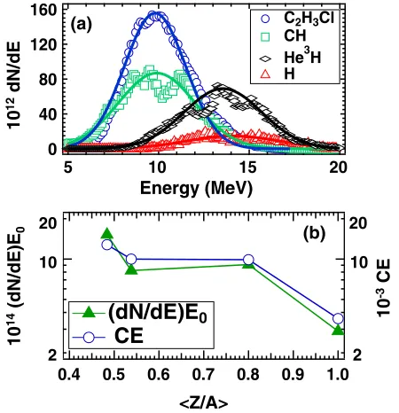
Figure 3(a)shows the energy distribution of accelerated
protons in the whole upstream region. We find that the energy
spread increases with increasinghZ=Ai. Simulations show
that this occurs at early times whenϕis relatively weak. This
is due to hole-boring on the front side of the target. These protons have a different velocity distribution and lower energies compared to the shock reflected protons, which results in the larger energy spread. The differences are
apparent in Figs.2(c)and2(d).
FIG. 2. A phase-space and velocity spectrum of the protons taken at Δx¼3μm in the upstream of the shock front at t¼4.0ps are shown for (a) C2H3Cl, (b) CH, (c) He3H, and
[image:4.612.328.547.52.536.2]The energy distribution of the shock reflected protons
multiplied by the peak energy in the distribution, E0, is
shown as a function of hZ=Ai in Fig. 3(b). The
laser-to-proton energy conversion efficiency (CE) is compared to the distribution in the same figure. Material with the lowest
hZ=Ai(C2H3Cl) show a CE almost an order of magnitude
higher than a pure proton target with the highest hZ=Ai.
In comparison, the peak energy of the distributions is
increasing by a comparatively small factor of ∼1.4from
C2H3Cl to H as shown in Fig.3(a).
Figures 4(a) and 4(b) show the x-y spatial profile of
the ES field, Ex, for the C2H3Cl upstream plasma. The
simulation box size is y¼6 and 20μm, respectively.
Both cases show a wavelike structure propagating in the x-direction, with increasing wavelength for largerx. TheEx
profile along the x-axis is averaged along the y-axis and
overlaid on the phase-space of the corresponding proton
velocity distribution in the upstream shown in Fig4(c). The
modulation inEx shows comparative correlation with the
proton phase-space distributions. These modulations are caused by the EITI in the upstream plasma. This is excited
by the relative drift velocity (vd) between the two ion
populations in plasmas with multi-ion species [23]. Our
simulations show that this relative drift is driven by the
ETNSA in the upstream plasma which results in slower
moving heavier ions with low hZ=Ai and faster moving
protons with highhZ=Ai. Simulations done by Zhang[26]
have shown that in the transverse size-reduced simulation
EITI propagates in the x-direction, whereas in the large
transverse size simulation it propagates obliquely. In our
case, since the propagation directions of EITI are in the x-direction both for the small and the large
transverse-size simulations [Figs.4(a)and4(b)], the instability is not
oblique but longitudinal.
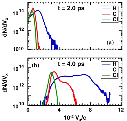
Temporal evolution of the upstream ion velocity
distri-bution dN=dVx in the C2H3Cl plasma is compared in
Figs.5(a)and5(b). These plots were captured just ahead
of the shock att¼2.0ps and 4.0 ps respectively. Initially,
vdis small and the instability has not established. As time
160
120
80
40
0
20 15
10 5
Energy (MeV)
C2H3Cl CH
He3H
H
2 4 6 8
10
2
1.0 0.9 0.8 0.7 0.6 0.5 0.4
<Z/A>
2 4 6 810 2
(dN/dE)E
0CE
(a)(b)
2 10 20
2 10 20
10
14
(dN/
dE
)E
0
10
-3
CE
10
12
dN/
dE
FIG. 3. (a) The energy spectra of the reflected protons in C2H3Cl (circles), CH (rectangles), He3H (diamonds) and,
H (triangles). (b) hZ=Ai dependencies of the ðdN=dEÞE0 and laser to the reflected protons conversion efficiency (CE) taken in the whole upstream region att¼4.0ps.
Y(
µ
m)
Y
(
µ
m)
X (
µ
m)
log
10[k
x(
µ
m
-1)]
log
10
[E
k
2
]
log
10
[E
k
2
]
E
x(10
11
V/m)
-0.4
1010 1011 1012 1013
2 4 6 8 10 12
10
-2
V
x/c
FIG. 4. 2D ES field (Ex) distribution averaged over two
laser-cycles in the upstream region at t¼4.0ps in C2H3Cl for the
simulations box size of (a) y¼6μm and (b) y¼20μm.
(c) Phase-space of the upstream expanding protons and 1D profile ofEx. Derived power spectrum ofExatt¼4.0ps taken
in the region of (d)x¼135–145μm and (e)x¼165–175μm.
KUMAR, SAKAWA, DÖHL, WOOLSEY, and MORACE PHYS. REV. ACCEL. BEAMS 22,043401 (2019)
[image:5.612.63.288.45.278.2]evolves, vd increases, which leads to a growth in the
instability. This results as shown in Fig. 5(b), in a
high-velocity tail in the C-ion and a low-high-velocity component to the proton distributions. We note that the chlorine distri-bution does not broaden in time. This observation suggests that the broadening of proton distributions discussed in
relation to Fig. 2results from the EITI.
Temporal evolution of the velocity at the peak of the dN=dVx distribution for Cl-ions, VCl (from the C2H3Cl
target) is plotted in Fig. 6. VCl shows a logarithmic
dependence with time indicating that VCl is determined
by the upstreamETNSA. By taking a derivative of a fit to the
VCldistribution withhZ=Ai ¼0.429, we infer that the time
dependentETNSAevolves with a1=tdependence as shown
in Fig. 6. The temporal variations for VCl and ETNSA
relationship described by Mora[34]. The time dependence
of the C-ion velocity (VC) at the peak ofdN=dVx agrees
well with calculations of VCbased on the inferred ETNSA
andhZ=Ai ¼0.5(VC−TNSA). Att¼2.5ps, a high-velocity
tail (VH
C) appears inVC. This results from acceleration by
an electric field associated with the EITI. The calculated
velocity for H-ions fromETNSA(VH−TNSA) withhZ=Ai ¼1,
which gives the maximum possible velocity for H-ions
caused byETNSA, is included for the comparison in Fig.6.
We approximate the simulated velocity distributions for
protons as a sum of the three 1D-shifted Maxwellian’s.
These velocities, the lower (VL
H), mean (VMH), and higher
(VH
H) velocity Maxwellian distributions are shown in Fig.6.
We note that VH
C and VLH represent the EITI accelerated
and decelerated C-ion and proton populations, respectively, and these populations have similar velocities. This occurs as an additional EITI develops due to the relative drift between the shock reflected proton population moving at
approx-imately2Vsh−V0, through the upstream expanding proton
population moving atV0. This further increases the number
of protons satisfying the condition for CSA.
B. Electrostatic ion two-stream instability In the cold plasma approximation, the dispersion relation
for EITI is given by [30]
1þ 1
k2
xλ2De¼ ω2
p1
ω2 þ
ω2
p2 ðω−kxvdÞ2
: ð1Þ
wherekx is the wave number in thex-direction,λDe is the
Debye length,ωp1 andωp2 are the proton and heavy ion
plasma frequencies, andvdis the relative drift between the
two ion populations. In multi-ion plasmas,ωp1is the proton
plasma frequency ωpp, and ωp2 is the heavy-ion plasma
frequency, as in,ωp2 is the carbon plasma frequencyωpc
for C2H3Cl and CH.
For C2H3Cl att¼4.0 ps, the maximum amplitude of the
modulation inExin the region ofx¼135–145 μm occurs at
kx ¼4.7×10⁶ m−1 [dashed line in Fig.4(d))], andλDe¼
0.4μm (for Ne ¼6.5×1020cm−3 and
Te ¼2 MeV) at
x¼140 μm in the upstream region. This results in
kxλDe>1, enabling us to neglect the second term on the
left-hand side of Eq. (1). At x¼140 μm, the carbon ion
and proton number densities areNC¼4×10
19 cm−3 and
Np¼1.3×1020 cm−3givingωpc¼ωpp¼1.5×10¹³sec−1.
Equation(1) has an unstable solution with the maximum
growth rate of ∼ωpc=2 at kx∼
ffiffiffi
3 p
ωpc=vd. We take vd¼
VH
H−VC¼0.042c att¼4.0ps. This gives,kx∼2.1×10
6m−1,
10
10 1012 1014 dN/dV x12
8
4
0
V
x/c (x10
-2)
H C Cl t = 2.0 ps
1010 1012 1014 dN/dV x 12 8 4 0 H C Cl t = 4.0 ps
1010
(a)
(b)
10-2V x/c
FIG. 5. Velocity spectrum of the expanding ions taken atΔx¼
3μm in the upstream region at (a)t¼2.0ps and (b)t¼4.0ps
in C2H3Cl.
8
6
4
2
0
2x100 3 4
VHH
VH L VH M VH-TNSA VC-TNSA ETNSA VCl
f t_VCl
VC
VC H
1.7 2.0 2.5 3.0 3.5 4.0
0.5 1 2 ETNSA (10 11 V/m) 10 -2 V0 /c Time (ps)
FIG. 6. Time evolution of the expanding ion speed in C2H3Cl.
The velocity of Cl-ionsVCl (open circles) is derived from the
peak of the velocity spectrum (dN=dVCl) taken atΔx¼3μm in
the upstream region and fitted to logarithmic curveVCl (solid
line).ETNSA(dotted line) is derived fromVCl and follows a1=t
dependence. Temporal variation of VC (filled triangles) agrees
well with the calculatedVC(VC−TNSA, dashed line) fromVCl.VHC
(open triangles) shows the high-velocity tail of C-ions, which appears att¼2.5ps, and overlaps with the lower-velocity (VL
H)
(open rectangles) component of H-ions. VH
H (filled rectangles)
represents the higher-velocity component of H-ions, which is larger than the velocity calculated fromETNSA [VH−TNSA,
[image:6.612.68.283.43.248.2] [image:6.612.328.547.45.170.2]which agrees relatively well with the value of kx¼4.7×
106m−1 extracted from simulation. We refer to this as
heavy-ion EITI.
Atx¼160μm,NC¼1×1019cm−3, which gives
ωpc¼
7.2×10¹² sec−1, and
vd¼0.040c at t¼4.0ps. Thus,
kx∼1.0×10⁶m−1, which is comparable to kx∼1.6×
106m−1 as shown in simulation in Fig.4(e). Hence, it is
clear from Figs.4(d)and4(e),kx decreases asxincreases
because the plasma density decreases as shown in
Fig.1(a) (t¼4.0 ps).
At t >2.5ps, the number of protons reflected by the shock front increases, which contributes to the excitation of the EITI between the expanding and the reflected protons. This is referred to as reflected-proton EITI. This
leads to the generation of a high-velocity tail inVH
H in the
upstream plasma. In the case of reflected-proton EITI,
ωp1¼ωpp and ωp2 is the reflected proton plasma
fre-quency ωpref. As shown in Fig. 2(a), the number of
reflected protons is smaller than that of the expanding
protons even at t¼4.0ps. Hence, ωpref<ωpp. The
maximum growth rate of reflected-proton EITI [30] is
∼ð3pffiffiffi3ðNref=NexpÞ=16Þ1=3ωppatkx∼ωpp=vrd. The relative
drift between the reflected and expanding protons isvr
d¼
0.064c at x ¼ 140μm and t¼4.0ps. Therefore,
kx∼6.8×10
5m−1, which is comparable to the
kx value
for the maximum growth rate of heavy-ion EITI at x ¼
140μmby a factor of 0.31. As a result, this suggests both that
heavy-ion and reflected-proton EITIs occur with similar growth rates and wave numbers.
VH−TNSA or the maximum possible velocity of H-ions
accelerated by ETNSA in C2H3Cl is shown in Fig.6. We
infer that a large number of protons is accelerated by the wave electric field of reflected-proton EITI and obtain
the expansion velocity V0 larger than VH−TNSA. This
acceleration generates a significant number of expanding
protons with the velocities larger thanVL, and results in
the enhancement of the shock accelerated protons.
Simulation studies done by Grassiet al.[35], have shown
that the development of ion turbulence in H plasma leads to the heating of upstream ions, which allows a fraction of ions to exceed the threshold for ion reflection from the shock front.
To confirm the effect ofhZ=Aion EITI, PIC-simulations
with the same laser and density properties used throughout are compared to fully ionized carbon deuterium (CD)
plasma. As shown in Fig. 7(a), since both C and D-ions
have the same hZ=Ai ¼0.5, both ions are accelerated by
ETNSAin the upstream plasma, and there is no relative drift
between them, as in, vd¼0. Therefore, no instability is
excited, and no broadening of the upstream ions occurs. In multi-ion plasmas, a high-velocity tail and a low-velocity
component appear in the smaller and larger hZ=Ai ions,
respectively. Figure7(b) represents upstream ion velocity
distribution for CCl2 plasma with fully ionized C and
ZCl¼10. A high-velocity tail in Cl-ions and a low-velocity
component of C-ions appear because of heavy-ion EITI.
III. DISCUSSION AND SUMMARY
We further generalize our results by finding the depend-ence of the peak energy of the reflected protons and proton
flux on the laser intensity corresponding to thea0¼3.35,
10, and 33. In order to compensate for relativistically induced transparency, the initial electron density is varied
1012
1014
10
8
6
4
2
0
V
x/c (x10
-2)
D C
1010
1012
1014
10 8
6 4
2 0
C Cl
dN/dV
x
dN/dV
x
(a)
(b)
10-2Vx/c
1010
FIG. 7. Velocity spectrum of the expanding ions in (a) CD and (b) CCl2 targets taken at Δx¼3μm in the upstream region at t¼4.0ps.
1 2 4 10
2 4 100
0
()
3 4 5 6 7
10
2 3 4a
0C2H3Cl H
1013
1014
1015
3 4 5 6 7
10
2 3 4a0
1 10 100
3
dN/dEC2H3Cl
dN/dEH
CEC2H3Cl
CEH
dN/
dE
10
-3
CE
3 10 40
E0
(MeV)
(a)
(b)
FIG. 8. (a) The peak energyE0of the shock reflected protons (b) the laser to proton conversion efficiency (CE) and the number of the shock accelerated protonsdN=dEat E0 in C2H3Cl and
H plasmas.
KUMAR, SAKAWA, DÖHL, WOOLSEY, and MORACE PHYS. REV. ACCEL. BEAMS 22,043401 (2019)
[image:7.612.320.553.44.272.2] [image:7.612.322.552.464.662.2]for different laser intensities by a0Ncr for all plasmas.
Figure 8 represents the peak energy (E0), conversion
efficiency (CE), and number (dN=dE atE0) of the shock
accelerated protons for different laser intensities
corre-sponding to a0¼3.35, 10, and 33 in C2H3Cl and H
plasmas. For C2H3Cl plasma,E0,dN=dE, and CE increase
with increasing laser intensity. However for H plasma,E0
and dN=dE increase but CE first increases and then
decreases with increasing laser intensity. The E0,
dN=dE, and CE are always larger for C2H3Cl plasma
compared to H plasma. As shown in Fig. 8(b), the
incre-ment in thedN=dEand CE for the higher laser intensity is
different from the lower laser intensity, whereas dN=dE
and CE of the shock accelerated protons are always higher
in lower hZ=Ai (C2H3Cl) plasma than pure H plasma.
At lower laser intensity (a0¼3.35), these increments are
found to be ∼8.6 and ∼4, while at higher laser intensity
(a0¼33), these increments are found to be∼2and∼1.3.
We have performed the 2D PIC simulations in a plane wave approximation with an infinite spot-size. In the 3D scenario a smaller amplitude TNSA field will appear on the
rear-side of the target according to Xiaoet al.[36], which
results in a quasimonoenergetic distribution for the CSA
ions[14]. Even with this small amplitude TNSA field, the
ions with differenthZ=Aiwill be accelerated to the different
velocities. This leads to the development of EITI in multi-ion species plasma.
In summary, we have presented a PIC simulation study of the ES collisionless shock proton acceleration in differ-ent target materials. Protons with high flux and narrower
energy spread can be produced using the lower hZ=Ai
materials. The excitation of heavy-ion EITI leads to a large velocity spread in the upstream region of protons in multi-ion materials. The velocity distributmulti-ion of the upstream expanding protons is further broadened toward the higher velocity by the EITI between reflected protons. As a result, a larger number of protons are driven by collisionless shock acceleration mechanism. This work supports future exper-imental work and investigations to a complete understand-ing of EITI and collisionless shocks usunderstand-ing accessible experimental parameters.
ACKNOWLEDGMENTS
This research was partially supported by Japan Society for the Promotion of Science (JSPS) KAKENHI Grant No. 15H02154 and by funding from Engineering and Physical Science Research Council (EPSRC) grant [EP/ L01663X/1] and Science and Technology Facilities Council (STFC).
[1] H. Daido, M. Nishiuchi, and A. S. Pirozkhov, Review of laser-driven ion sources and their applications,Rep. Prog. Phys.75, 056401 (2012).
[2] A. Macchi, M. Borghesi, and M. Passoni, Ion acceleration by superintense laser-plasma interaction,Rev. Mod. Phys.
85, 751 (2013).
[3] M. Roth, T. E. Cowan, M. H. Key, S. P. Hatchett, C. Brown, W. Fountain, J. Johnson, D. M. Pennington, R. A. Snavely, S. C. Wilks, K. Yasuike, H. Ruhl, P. Pegoraro, S. V. Bulanov, E. M. Campbell, M. D. Perry, and H. Powell, Fast Ignition by Intense Laser-Accelerated Proton Beams,Phys. Rev. Lett.
86, 436 (2001).
[4] S. V. Bulanov, T. Z. Esirkepov, V. S. Khororshkov, A. Z. Kuznetsov, and F. Pegoraro, Oncological hadron-therapy with laser ion accelerators,Phys. Lett. A299, 240 (2002).
[5] U. Linz and J. Alonso, What will it take for laser driven proton accelerators to be applied to tumor therapy?,Phys. Rev. ST Accel. Beams10, 094801 (2007).
[6] F. Wagner, O. Deppert, C. Brabetz, P. Fiala, A. Kleinschmidt, P. Poth, V. A. Schanz, A. Tebartz, B. Zielbauer, M. Roth, T. Stohlker, and V. Bagnoud, Maxi-mum Proton Energy above 85 MeV from the Relativistic Interaction of Laser Pulses with Micrometer Thick CH2 Targets,Phys. Rev. Lett.116, 205002 (2016).
[7] A. Higginson, R. J. Gray, M. King, R. J. Dance, S. D. R. Williamson, N. M. H. Butler, R. Wilson, R. Capdessus, C. Armstrong, J. S. Green, S. J. Hawkes, P. Martin, W. Q. Wei, S. R. Mirfayzi, X. H. Yuan, S. Kar, M. Borghesi, R. J. Clarke, D. Neely, and P. McKenna, Near-100 MeV protons via a laser-driven transparency-enhanced hybrid acceler-ation scheme,Nat. Commun. 9, 724 (2018).
[8] I. J. Kim, K. H. Pae, W. Choi, C. L. Lee, H. T. Kim, H. Singhal, J. H. Sung, S. K. Lee, H. W. Lee, P. V. Nickles, T. M. Jeong, C. M. Kim, and C. H. Nam, Radiation pressure acceleration of protons to 93 MeV with circularly polarized petawatt laser pulses,Phys. Plasmas23, 070701 (2016).
[9] F. Dollar, C. Zulick, A. Raymond, V. Chvykov, L. Willingale, V. Yanovsky, A. Maksimchuk, A. G. R. Thomas, and K. Krushelnick, Enhanced laser absorption from radiation pressure in intense laser plasma interactions, New J. Phys.19, 063014 (2017).
[10] A. Henig, S. Steinke, M. Schnurer, T. Sokollik, R. Horlein, D. Kiefer, D. Jung, J. Schreiber, B. M. Hegelich, X. Q. Yan, J. Meyer-ter-Vehn, T. Tajima, P. V. Nickles, W. Sandner, and D. Habs, Radiation-Pressure Acceleration of Ion Beams Driven by Circularly Polarized Laser Pulses,Phys. Rev. Lett.103, 245003 (2009).
[11] J. Denavit, Absorption of High-Intensity Subpicosecond Lasers on Solid Density Targets,Phys. Rev. Lett.69, 3052 (1992).
[12] L. O. Silva, M. Marti, J. R. Davies, R. A. Fonseca, C. Ren, F. S. Tsung, and W. B. Mori, Proton Shock Acceleration in Laser-Plasma Interactions, Phys. Rev. Lett. 92, 015002 (2004).
[13] F. Fiuza, A. Stockem, E. Boella, R. A. Fonseca, L. O. Silva, D. Haberberger, S. Tochitsky, C. Gong, W. B. Mori, and C. Joshi, Laser-Driven Shock Acceleration of Monoenergetic Ion Beams,Phys. Rev. Lett.109, 215001 (2012). [14] T. Grismayer and P. Mora, Influence of a finite initial ion
[15] D. Haberberger, S. Tochitsky, F. Fiuza, C. Gong, R. A. Fonseca, L. O. Silva, W. B. Mori, and C. Joshi, Collision-less shocks in laser-produced plasma generate monoener-getic high-energy proton beams,Nat. Phys.8, 95 (2012). [16] P. Antici, E. Boella, S. N. Chen, D. S. Andrews, M. Barberio, J. Bker, F. Cardelli, J. L. Feugeas, M. Glesser, P. Nicola, L. Romagnani, M. Scisci, M. Starodubtsev, O. Willi, J. C. Kieffer, V. Tikhonchuk, H. Ppin, L. O. Silva, E. d Humires, and J. Fuchs, Acceleration of collimated 45 MeV protons by collisionless shocks driven in low-density, large-scale gradient plasmas by a 1020W/cm2,
1μm laser,Sci. Rep.7, 16463 (2017).
[17] A. Pak, S. Kerr, N. Lemos, A. Link, P. Patel, F. Albert, L. Divol, B. B. Pollock, D. Haberberger, D. Froula, M. Gauthier, S. H. Glenzer, A. Longman, L. Manzoor, R. Fedosejevs, S. Tochitsky, C. Joshi, and F. Fiuza, Collision-less shock acceleration of narrow energy spread ion beams from mixed species plasmas using1μm lasers,Phys. Rev.
Accel. Beams21, 103401 (2018).
[18] H. Zhang, B. F. Shen, W. P. Wang, S. H. Zhai, S. S. Li, X. M. Lu, J. F. Li, R. J. Xu, X. L. Wang, X. Y. Liang, Y. X. Leng, R. X. Li, and Z. Z. Xu, Collisionless Shock Accel-eration of High-Flux Quasimonoenergetic Proton Beams Driven by Circularly Polarized Laser Pulses,Phys. Rev. Lett.119, 164801 (2017).
[19] O. Tresca, N. P. Dover, N. Cook, C. Maharjan, M. N. Polyanskiy, Z. Najmudin, P. Shkolnikov, and I. Pogorelsky, Spectral Modification of Shock Accelerated Ions Using a Hydrodynamically Shaped Gas Target, Phys. Rev. Lett.
115, 094802 (2015).
[20] H. Zhang, B. F. Shen, W. P. Wang, Y. Xu, Y. Q. Liu, X. Y. Liang, Y. X. Leng, R. X. Li, X. Q. Yan, J. E. Chen, and Z. Z. Xu, Collisionless shocks driven by 800 nm laser pulses generate high-energy carbon ions, Phys. Plasmas
22, 013113 (2015).
[21] M. Liu, S. M. Weng, Y. T. Li, D. W. Yuan, M. Chen, P. Mulser, Z. M. Sheng, M. Murakami, L. L. Yu, X. L. Zheng, and J. Zhang, Collisionless electrostatic shock formation and ion acceleration in intense laser interactions with near critical density plasmas,Phys. Plasmas23, 113103 (2016). [22] T. D. Arber, K. Bennett, C. S. Brady, A. L. Douglas, M. G. Ramsay, N. J. Sircombe, P. Gillies, R. G. Evans, H. Schmitz, A. R. Bell, and C. P. Ridger, Contemporary particle-in-cell approach to laser-plasma modelling, Plasma Phys. Controlled Fusion57, 113001 (2015). [23] H. Karimabadi, N. Omidi, and K. Quest, Two‐dimensional
simulations of the ion/ion acoustic instability and electro-static shocks,Geophys. Res. Lett.18, 1813 (1991). [24] G. Sarri, G. C. Murphy, M. E. Dieckmann, A. Bret,
K. Quinn, I. Kourakis, M. Borghesi, L. Drury, and A.
Ynnerman, Two-dimensional particle-in-cell simulation of the expansion of a plasma into a rarefied medium,New J. Phys.13, 073023 (2011).
[25] H. G. Rinderknecht, H. S. Park, J. S. Ross, P. A. Amendt, D. P. Higginson, S. C. Wilks, D. Haberberger, J. Katz, D. H. Froula, N. M. Hoffman, G. Kagan, B. D. Keenan, and E. L. Vold, Highly Resolved Measurements of a Developing Strong Collisional Plasma Shock, Phys. Rev. Lett.120, 095001 (2018).
[26] W. S. Zhang, H. B. Cai, and S. P. Zhu, The formation and dissipation of electrostatic shock waves: the role of ion–ion
acoustic instabilities,Plasma Phys. Controlled Fusion60, 055001 (2018).
[27] M. King, R. J. Gray, H. W. Powell, R. Capdessus, and P. Mckenna, Energy exchange via multi-species streaming in laser-driven ion acceleration, Plasma Phys. Controlled Fusion59, 014003 (2017).
[28] J. S. Ross, H.-S. Park, R. Berger, L. Divol, N. L. Kugland, W. Rozmus, D. Ryutov, and S. H. Glenzer, Collisionless Coupling of Ion and Electron Temperatures in Counter-streaming Plasma Flows, Phys. Rev. Lett. 110, 145005 (2013).
[29] T. N. Kato and H. Takabe, Electrostatic and electromag-netic instabilities associated with electrostatic shocks: Two-dimensional particle-in-cell simulation, Phys. Plas-mas17, 032114 (2010).
[30] Y. Ohira and F. Takahara, Oblique ion two-stream insta-bility in the foot region of a collisionless shock,Astrophys. J.688, 320 (2008).
[31] W. L. Kruer and K. G. Estabrook, J×B heating by very intense laser light,Phys. Fluids28, 430 (1985).
[32] D. A. Tidman and N. A. Krall, Shock Waves in Collisionless Plasmas (Wiley-Interscience, New York, 1971).
[33] A. P. L. Robinson, D. Neely, P. McKenna, and R. G. Evans, Spectral control in proton acceleration with multi-ple laser pulses,Plasma Phys. Controlled Fusion49, 373 (2007).
[34] P. Mora, Plasma Expansion into a Vacuum,Phys. Rev. Lett.
90, 185002 (2003).
[35] A. Grassi, L. Fedeli, A. Sgattoni, and A. Macchi, Vlasov simulation of laser-driven shock acceleration and ion turbulence, Plasma Phys. Controlled Fusion 58, 034021 (2016).
[36] K. D. Xiao, C. T. Zhou, K. Jiang, Y. C. Yang, R. Li, H. Zhang, B. Qiao, T. W. Huang, J. M. Cao, T. X. Cai, M. Y. Yu, S. C. Ruan, and X. T. He, High Z neoclassical trans-port: Application and limitation of analytical formulae for modelling JET experimental parameters,Phys. Plasmas25, 012303 (2018).
KUMAR, SAKAWA, DÖHL, WOOLSEY, and MORACE PHYS. REV. ACCEL. BEAMS 22,043401 (2019)