Research Article Vol. 27, No. 19 / 16 September 2019 /Optics Express26799
Efficiency improvements in a dichroic
dye-doped liquid crystal Fresnel lens
ETHAN
I. L. JULL,
1,*MARKUS
WAHLE,
1PETER
J. M.
WYATT,
1COLIN
ELLIS,
2STEPHEN
J. C
OWLING,2JOHN
W.
GOODBY,
2KIYOAKI
USAMI
,
3 ANDHELEN
F. GLEESON
11School of Physics and Astronomy, University of Leeds, LS2 9JT, UK
2Department of Chemistry, University of York, Heslington, York YO10 5DD, UK 3Osaka Sangyo University, 3-1-1 Nakagaito, Daito-shi, Osaka 574-8530, Japan
*py12ej@leeds.ac.uk
Abstract: A dichroic dye-doped liquid crystal Fresnel lens was fabricated and investigated to
observe the combination of phase and amplitude modulation based focusing. An anthraquinone dichroic dye was doped into a liquid crystal host, which when in the Fresnel lens configuration, generates a Fresnel zone plate with alternating “transparent” and “opaque” zones. The zones were induced by using photo-alignment of a light-sensitive alignment layer to generate the alternating pattern. The voltage dependency of efficiency for the dye-doped and pure liquid crystal Fresnel devices were investigated. Incorporation of dyes into the device yielded a significant 4% improvement in relative efficiency in the lens, giving a maximum of 37% achieved in the device, much closer to the theoretical 41% limit when compared with the non-dye-doped device. The input polarization dependence of efficiency was also investigated, showing very small fluctuations (±1.5%), allowing further insight into the effect of fabrication method on these liquid crystal Fresnel devices.
Published by The Optical Society under the terms of theCreative Commons Attribution 4.0 License. Further distribution of this work must maintain attribution to the author(s) and the published article’s title, journal citation, and DOI.
1. Introduction
The electro-optical properties of liquid crystals [1] (LC) make them incredibly efficient and versatile light manipulators, so that they are ubiquitous in display and non-display technologies. The ease of refractive index modulation, through the application of electric fields (E-field) or external light stimuli, makes them ideal for use in Fresnel technology. The lack of moving parts in LC devices is a clear advantage allowing for simple and direct control of light. Switchable Fresnel lenses are utilised in optical communications, display systems, optical information processing, imaging, and projection. LC Fresnel lens technology has been previously demonstrated through a multitude of methods including; electrode patterning [2–8], polymer-stabilisation [9–14], polymer-relief structures [15–17], polymer-dispersed LCs [18,19], light induced phase effects of azo-doped LCs [20,21], alignment microrubbing [22], UV modification of alignment anchoring strength [23,24], photo-alignment through azo-dopant alignment layer absorption [25–27], and direct substrate photo-alignment [28–33].
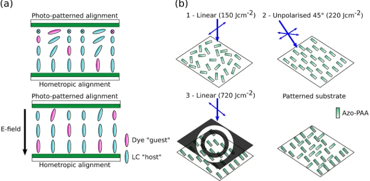
The LC Fresnel lens reported here was fabricated using direct substrate photo-alignment [34]. Alternating zones of orthogonal director alignment were created on one surface, which generated the Fresnel pattern, with the other surface treated for homeotropic alignment, Fig.1(a). This device geometry creates an alternating hybrid aligned nematic (HAN) director field inside the device. Previous dye-doped LC Fresnel lens devices have focused on the use of doped dyes either to generate alternating alignment directions [25–27] or to photo-induce zone specific phase transitions [20,21], and have not investigated their potential impact on efficiency. Use of the dichroic dyes in the LC will generate alternating “opaque” and “transparent” zones which is in
effect a Fresnel zone plate. Fresnel zone plates focus light via amplitude modulation (similar to a standard diffraction grating). However, when considering a dye doped LC Fresnel lens the amplitude modulation focusing will combine with the phase focusing effects of the birefringent material. This report investigates the direct effect of an anthraquinone dichroic dye [35] amplitude modulation based focusing on the efficiency of a switchable dye-doped guest-host LC Fresnel lens.
Fig. 1.(a) Schematic of the HAN director field inside the photo-patterned LC Fresnel lens.
(b) The photo-patterning process used to generate the Fresnel director pattern in the LC device.
Anthraquinone dichroic dyes have a transition moment approximately parallel to the molecular long axis, which results in a polarization angle dependent absorption. When doped into a LC (host) the dichroic dye (guest) will be oriented by the bulk LC director [36], with the dye long-axis parallel to the director. Therefore, when a LC Fresnel device configuration is considered, a Fresnel zone plate with alternating strongly absorbing and weakly absorbing zones is generated. Fresnel zone plates have a maximum theoretical relative efficiency (ratio of the focused spot intensity to the total transmitted intensity, used commonly in LC Fresnel characterization [4, 10, 16, 19, 20, 23, 25, 30 & 33]) of∼21% (∼10.5% absolute efficiency). The light transmitted through this LC Fresnel device will therefore undergo amplitude modulation based focusing due to the alternating absorption caused by the dichroic dye guest-host effect, determined by components of the parallel and perpendicular absorption coefficients,a| |anda⊥. Under application of a sufficiently large E-field (the threshold voltage of the device must be exceeded) the director will re-orient and approach the homeotropic (HT) alignment state. This will remove the contrast between zones and the dye absorption will become constant across the device, removing the amplitude-focusing effect. The LC Fresnel device will also focus light due to the inherent birefringence of the LC that causes a phase-shift between alternate zones,Φ=2π∆nd/λ, where∆n is the birefringence, d
is the cell gap, andλthe wavelength. The peak in efficiency due to the phase effect occurs when
Φ=π(maximum theoretical efficiency∼41%). The refractive index difference between zones can also be controlled via E-field application, and eventually reduced to zero when the device approaches the HT state.
Research Article Vol. 27, No. 19 / 16 September 2019 /Optics Express26801
2. Materials and methods
The LC Fresnel lens described here was fabricated using a masked photo-alignment technique. The photomask was designed with rings of radii;Rn =
q
nλ f +nλ4 , whereλ=532 nm, n is
the ring number (156 total rings, Rmax=5 mm), and f the focal point is 0.3 m. A polyamic
acid-containing azobenzene in the backbone structure (Azo-PAA, obtained from JNC Petrochemical Co.) [34] was spin coated onto indium tin oxide (ITO) glass before being treated with a 3-step patterning technique, depicted in Fig.1(b). Initial irradiation of the substrate with linearly polarised light (150 Jcm−2) gives homogenous planar alignment perpendicular to the irradiation polarization. The substrate is then irradiated with unpolarised UV light at 45 ° incidence angle (220 Jcm−2), inducing a pre-tilt angle of∼2 °. The pre-tilt is induced due to the affinity for the Azo-PAA to orient perpendicular to the UV irradiation polarization. In this case it is unpolarised and therefore results in a preferred orientation into the irradiation direction, more information on this alignment technique can be found in [34]. This step is introduced into the fabrication process to remove defect lines generated by reverse-splay HAN domains which would occur for 0 ° pre-tilt and cause scattering in the final implementation of the device. Finally, a chrome photomask is placed in contact with the substrate and then irradiated with linear polarised light at 90 ° to the first irradiation (720 Jcm−2). This generates orthogonal alignment in the photomask transparent zones with a 0 ° pre-tilt angle. The substrate is then baked at 250 °C for 2 hours to fix the alignment. To create the bottom HT aligned substrate, a side-chain-containing AZO-PAA [37] was spin coated onto ITO glass and then baked. The device was then assembled using 50 µm spacer film, chosen to give optimal contrast between orthogonal dye doped zones, calculated from 15NB3 guest-host absorption coefficients and the Beer-Lambert law (a//=0.11%−1µm−1 and a⊥=0.0087%−1µm−1).
The LC host chosen for this study was MLC-7023 (∆n=0.0609 and∆=7.9) obtained from
Merck Chemicals Ltd.. This LC was doped, close to the solubility limit, with 0.50%(w/w) 15NB3 anthraquinone dye (λmax=540 nm) synthesized at the University of York [38]. Both pure
and dye doped devices were fabricated for direct comparison.
3. Results and discussion
The effective birefringence (∆neff) for each sample was measured in the HAN device (λ=589 nm)
configuration with varying voltage from 0 to 20 Vrms(Fig.2(a)). For MLC-7023,∆neffvaries
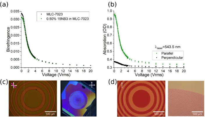
from 0.034→0.001, whilst 15NB3-doped MLC-7023 has a slightly lower birefringence, varying from 0.031→0.001, due to the difference in composition. The measurements of birefringence allow the phase shift in the device to be calculated, allowing a direct comparison of efficiency measurements between samples. The absorption of green laser light (λ=543.5 nm) polarised parallel and perpendicular to the bulk director (A// and A⊥) was characterized as a function of voltage through use of a photodiode, Fig.2(b). At 0 VrmsA//=(0.95±0.02) OD, much larger compared to A⊥=(0.372±0.005) OD. Upon increasing voltage, the contrast in absorption, ∆A=A//-A⊥, decreases as each zone approaches the HT state, going from∆A=(0.57±0.02) OD to∆A=(0.029±0.001) OD. Thus, a continuous reduction in amplitude modulation focusing is generated in the dye doped LC Fresnel lens device.
Polarizing optical microscopy (POM) was used to image the LC Fresnel lens, as shown in Figs.2(c) and 2(d). Excellent alignment in each device is observed. Figure2(c) is the MLC-7023 sample viewed between crossed polarisers, with aλ-plate allowing the orthogonal alignment to be observed. Figure2(d) shows the dye doped sample viewed with a single input polariser, clearly demonstrating the alternating zone absorption effects that are under investigation here. The colour intensity alternates between zones due to orthogonal director alignment.
The focusing efficiency of the device was measured as a function of voltage (0 - 20 Vrms,
Research Article Vol. 27, No. 19 / 16 September 2019 /Optics Express26802
when Φ=π (Φ
the small (~3 will impact th
Φ/π=1; nonet focusing effic to maximum d
Fig doped parall MLC bulk s of Figure 3(a 15NB3 doped The dye dope which corresp 3.5 % improv addition of th demonstrates pure LC Fres device imperf clear improve When compar ~4 % can pro low voltages ordered at the and relative dichroic dye therefore a low
Φ/π=1), with Φ
%) wavelength he calculated p
theless this ca ciency compon dye contrast, an
g. 2. (a) The birefr d MLC-7023. (b) T
lel and perpendicu C-7023 between cro shown between cro f the LC Fresnel de 0/90 °)
a) shows how d MLC-7023 d ed sample pro pond to the pe vement is also he amplitude-fo how these va nel lens demo fections e.g. s ement, moving
ring devices th vide quite an a
due to the sc ese lower volta efficiencies of in the system wer absolute e
Φ continuously h dispersion an phase shift, and alculation give nent will theore nd will then de
ingence as a funct The absorption of ular light polarisati ossed polarisers w ossed polarisers. ( evice 15NB3 dope ). All data can be f
w the relative e devices (this p ovides a 4 % i eaks in efficien o observed. Th ocusing effects alues for effici nstrated here i cattering from the device tow his close to the
advantage over cattering at the ages. Figure 3(b f the dye dop m results in a l
fficiency.
decreasing wi nd temperature d therefore the s a facile com etically start at ecrease continu
tion of voltage is sh 15NB3 doped ML ions. (c) POM ima with a λ-plate (direc d) POM image sho ed MLC-7023 with
found at https://do
efficiency vari parameter vari increase in eff ncy. Away from
he improveme s, which are in iency compare is slightly low m zone bounda wards the top e
maximum theo r other devices e zone bounda b) demonstrate ped Fresnel de lower overall
ith increasing v e dependence o
peak in efficie mparison of de t a maximum a uously with inc
hown for MLC-70 LC-7023 as a funct age showing the LC
ctor(s) at ±45 °). E owing the central h a single polariser oi.org/10.5518/588
ies with Φ/π f ies as the appl ficiency in the m the phase-fo ents to efficien ndependent of t
e with previou wer than similar
aries), the dye end of currently
oretical efficie s. The measure aries where th es the differenc evice. The abs transmission t
voltage. It is n of the LC bire ency vary sligh evices. The am at 0 Vrms, corre
creasing voltag
023 and 15NB3 tion of voltage for C Fresnel devices Example device in and radial regions r (director(s) at 8.
for the MLC-7 lied voltage in e phase-focusin ocusing states, ncy are a resu the phase shift us literature. W
r devices (like doped device y achieved eff ency an improv ed efficiency is he director fiel ce between the sorption cause through the de
noted that fringence htly from mplitude-esponding ge. r s 7023 and ncreases). ng states, , Φ≠nπ, a ult of the t. Table 1 Whilst the ely due to shows a ficiencies. vement of s lower at ld is less e absolute ed by the
[image:4.612.130.482.92.294.2]evice and
Fig. 2.(a) The birefringence as a function of voltage is shown for MLC-7023 and 15NB3
doped MLC-7023. (b) The absorption of 15NB3 doped MLC-7023 as a function of voltage for parallel and perpendicular light polarisations. (c) POM image showing the LC Fresnel devices MLC-7023 between crossed polarisers with aλ-plate (director(s) at±45 °). Example device in bulk shown between crossed polarisers. (d) POM image showing the central and radial regions of the LC Fresnel device 15NB3 doped MLC-7023 with a single polariser (director(s) at 0/90 °). All data can be found athttps://doi.org/10.5518/588.
efficiency () is defined as the ratio of the focused spot intensity (I) (measured using a 200 µm pinhole situated at the focal point) to the total intensity transmitted through the device (I0),=I/I0.
This definition of diffraction efficiency is commonly used in measuring Fresnel efficiency [4, 10, 16, 19, 20, 23, 25, 30, & 33] and ignores optical reflections or absorption. The absolute efficiency measured in the device will also be demonstrated. The device will exhibit losses with respect to the initial intensity due to dye absorption, and therefore lower absolute efficiency maxima as observed in other amplitude based focusing systems.
To account for the difference in the birefringence of the mixtures (Fig.2(a)), as well as the small cell gap differences between the devices (50.3 and 50.5 µm), the applied voltage was converted to the equivalent phase shift,Φ/π=2∆nd/λ, to allow a clear comparison between
measurements. The maximum phase focusing efficiency component will theoretically occur whenΦ=π(Φ/π=1), withΦcontinuously decreasing with increasing voltage. It is noted that
the small (∼3%) wavelength dispersion and temperature dependence of the LC birefringence will impact the calculated phase shift, and therefore the peak in efficiency vary slightly from
Φ/π=1; nonetheless this calculation gives a facile comparison of devices. The amplitude-focusing
efficiency component will theoretically start at a maximum at 0 Vrms, corresponding to maximum
dye contrast, and will then decrease continuously with increasing voltage.
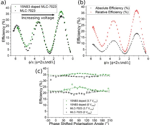
Figure3(a) shows how the relative efficiency varies withΦ/πfor the MLC-7023 and 15NB3
doped MLC-7023 devices (this parameter varies as the applied voltage increases). The dye doped sample provides a 4% increase in efficiency in the phase-focusing states, which correspond to the peaks in efficiency. Away from the phase-focusing states,Φ,nπ, a 3.5% improvement is also
Research Article Vol. 27, No. 19 / 16 September 2019 /Optics Express26803
boundaries), the dye doped device shows a clear improvement, moving the device towards the top end of currently achieved efficiencies. When comparing devices this close to the maximum theoretical efficiency an improvement of∼4% can provide quite an advantage over other devices. The measured efficiency is lower at low voltages due to the scattering at the zone boundaries where the director field is less ordered at these lower voltages. Figure3(b) demonstrates the difference between the absolute and relative efficiencies of the dye doped Fresnel device. The absorption caused by the dichroic dye in the system results in a lower overall transmission through the device and therefore a lower absolute efficiency.
The polar efficiency me polarisation a director. Typ polarization i with respect t of the alignme dependence o different type here in turn.
Fig. 3 ML do eff tilte Maximum eff 37 33 34.1 38. 35 35 34
In the case and increases towards the m is Δn=ne,ϴ-no,
refractive ind extraordinary °, a small inc
rization angle easurements a angle correspon
pically, a Fre ndependence, o input polariz ent layer pre-ti of each device es of focal effe
3. (a) The relative e LC-7023 Fresnel d
oped MLC-7023 F ficiency for each d
[image:5.612.181.435.202.413.2]d” zone director. F
Table 1. Co
ficiency (%) 7 3 14 5 5 5 4
e of the pure M s in voltage maximum. Whe
, where ne,ϴ is
ex. At 90 ° the refractive inde crease in biref
dependency t 0 Vrms (Φ≠π
nds to the align esnel device however here zation angle is m
ilt angle (~2 °) is 90 ° out o cts (phase or a
efficiency as a fun evices. (b) Compa Fresnel device. (c) device. 0 ° correspo Fit parameters can
omparison of ortho
[25] – Orthog surface. [28] – Orthogon [31] – Orthogon [32] – Orthogon [33] – Orthogon
MLC-7023 devi (decrease in p en the input po the pre-tilted e e birefringence ex. This means fringence is ob
of this devic
π) and 3.7 Vr nment of the p with orthogo a small varia measured (max
that occurs on f phase with r amplitude mod
nction of phase shi arison of absolute a
The polarization a onds to alignment n be found in the da
ogonal HAN LC F
Refere This work: (15N
This wor gonal HAN zon
nal HAN zones v nal HAN zones v nal HAN zones v nal HAN zones v
ice at 0 Vrms th phase-shift/bir olarization is a extraordinary r e between zone
s that on rotatin bserved, movin
ce was thorou rms (Φ=π) (Fig polarisation of
onal alignmen ation in the eff ximum ±1.5 % nly in the even respect to the dulation), each
ift for MLC-7023 a and relative efficie angle dependence of the polarization ataset https://doi.o
Fresnel lens efficie
ence/Comment NB3 doped MLC
rk: (MLC-7023) nes via methy
via masked phot via masked phot via masked phot via photolithogr
he device is not refringence) in at 0 ° the birefr refractive index es is simply Δn ng the input po ng the device
ughly investig g. 3(c)). Note light with the nt zones wou ficiency of eac %). This is a dir zones. The po other, the resu
of which is co
and 15NB3 doped ency for 15NB3
of the relative n with the “pre-org/10.5518/588. encies. C-7023) ) yl-red absorption to-alignment. to-alignment. to-alignment. raphy & rubbing
t in the Φ=nπ c ncreases the e ringence betwe x and no is the n=ne-no, where olarisation from
further away
gated via that 0 ° pre-tilted uld have ch device rect result larization ult of the onsidered d n onto g. condition, efficiency een zones e ordinary e ne is the m 0 to 90 from the
Fig. 3.(a) The relative efficiency as a function of phase shift for MLC-7023 and 15NB3 doped
[image:5.612.118.497.515.625.2]MLC-7023 Fresnel devices. (b) Comparison of absolute and relative efficiency for 15NB3 doped MLC-7023 Fresnel device. (c) The polarization angle dependence of the relative efficiency for each device. 0 ° corresponds to alignment of the polarization with the “pre-tilted” zone director. Fit parameters can be found in the datasethttps://doi.org/10.5518/588.
Table 1. Comparison of orthogonal HAN LC Fresnel lens efficiencies.
Maximum efficiency (%) Reference/Comment
37 This work: (15NB3 doped MLC-7023) 33 This work: (MLC-7023)
34.14 [25] – Orthogonal HAN zones via methyl-red absorption onto surface. 38.5 [28] – Orthogonal HAN zones via masked photo-alignment.
35 [31] – Orthogonal HAN zones via masked photo-alignment. 35 [32] – Orthogonal HAN zones via masked photo-alignment. 34 [33] – Orthogonal HAN zones via photolithography & rubbing.
The polarization angle dependency of this device was thoroughly investigated via efficiency measurements at 0 Vrms(Φ,π) and 3.7 Vrms(Φ=π) (Fig.3(c)). Note that 0 ° polarisation angle
measured (maximum±1.5%). This is a direct result of the alignment layer pre-tilt angle (∼2 °) that occurs only in the even zones. The polarization dependence of each device is 90 ° out of phase with respect to the other, the result of the different types of focal effects (phase or amplitude modulation), each of which is considered here in turn.
In the case of the pure MLC-7023 device at 0 Vrmsthe device is not in theΦ=nπcondition, and
increases in voltage (decrease in phase-shift/birefringence) increases the efficiency towards the maximum. When the input polarization is at 0 ° the birefringence between zones is∆n=ne,Θ-no,
where ne,Θis the pre-tilted extraordinary refractive index and nois the ordinary refractive index.
At 90 ° the birefringence between zones is simply∆n=ne-no, where ne is the extraordinary
refractive index. This means that on rotating the input polarisation from 0 to 90 °, a small increase in birefringence is observed, moving the device further away from the phase-focusing peak, effectively reducing the efficiency. This can be observed in Fig.3(c) where the MLC-7023 device efficiency without an applied voltage starts with a maximum value at 0 ° and decreases slightly to a minimum at 90 °. The same effect, although smaller due to the decrease in zone difference under applied voltage, is observed when 3.7 Vrmsis applied; the shift in birefringence
again moves away from the peak in efficiency.
In the case of the 15NB3 doped MLC-7023 device at 0 Vrms we have a large difference
between A//and A⊥. At 0 ° input polarization angle there is an effective contrast between zones ∆A=AΘ-A⊥, where AΘis the absorption parallel to the long axis of the pre-tilted director. When the input polarization is at 90 ° there is an effective contrast between zones of∆A=A//-A⊥, which is greater than the contrast at 0 °. Therefore, on rotation from 0 to 90 ° we get an increase in absorption contrast and therefore an increase in the amplitude-focusing effect. This can be observed in Fig.3(c) where the 15NB3 doped MLC-7023 efficiency starts at a minimum at 0 ° and increases towards a maximum at 90 °. The same effect is observed at 3.7 Vrms, although
with a smaller amplitude, again due to the decrease in zone difference under an applied voltage.
4. Conclusion
Development of a dye doped guest-host LC Fresnel lens has been undertaken to investigate the effect of amplitude modulation focusing on the relative efficiency of the Fresnel device. Inclusion of an anthraquinone dichroic dye into the LC host generates a clear improvement in the maximum efficiency of the device from 33 to 37%. Application of a voltage across the device allows the efficiency to be controlled, approaching 0% at voltages∼20 Vrms, offering a clear variation from focusing to non-focusing. The polarization dependence of the device was investigated and shown to vary due to device pre-tilt, by up to±1.5% depending on the input polarization angle. This can be attributed to the difference in the pre-tilt alignment of the different zones, and it is noted that the dependency can be removed if device fabrication ensures identical pre-tilt angle between zones.
Funding
Engineering and Physical Sciences Research Council (EP/N509681/1); Daiwa Anglo-Japanese Foundation (11847/12639); Merck Chemicals ltd..
Acknowledgments
We would like to thank JNC Petrochemical Co. for supplying the polyamic acid solution used in this work.
References
Research Article Vol. 27, No. 19 / 16 September 2019 /Optics Express26805
2. G. Li, P. Valley, M. S. Giridhar, D. L. Mathine, G. Meredith, J. N. Haddock, B. Kippelen, and N. Peyghambarian, “Large-aperture switchable thin diffractive lens with interleaved electrode patterns,”Appl. Phys. Lett.89(14), 141120
(2006)..
3. G. Li, D. L. Mathine, P. Valley, P. Ayras, J. N. Haddock, M. S. Giridhar, G. Williby, J. Schwiegerling, G. R. Meredith, B. Kippelen, S. Honkanen, and N. Peyghambarian, “Switchable electro-optic diffractive lens with high efficiency for ophthalmic applications,”Proc. Natl. Acad. Sci. U. S. A.103(16), 6100–6104 (2006).
4. W. Hung, Y. Chen, C. Lin, I. Jiang, and T. Hsu, “Sensitive voltage-dependent diffraction of a liquid crystal Fresnel lens,”Appl. Opt.48(11), 2094–2098 (2009).
5. Y. huang, C. Chen, and Y. Huang, “Superzone Fresnel liquid crystal lens for temporal scanning auto-stereoscopic display,”J. Disp. Technol.8(11), 650–655 (2012).
6. S. Lin, B. Huang, C. Li, K. Yu, J. Chen, and C. Kuo, “Electrically and optically tunable Fresnel lens in a liquid crystal cell with a rewritable photoconductive layer,”Opt. Mater. Express6(7), 2229–2235 (2016).
7. H. Dou, F. Chu, Y. Song, G. Li, and Q. Wang, “A multifunctional blue phase liquid crystal lens based on multi-electrode structure,”Liq. Cryst.45(4), 491–497 (2018).
8. A. Jamali, D. Bryant, Y. Zhang, A. Grunnet-Jepsen, A. Bhowmik, and P. Bos, “Design of a large aperture tunable refractive Fresnel liquid crystal lens,”Appl. Opt.57(7), B10–B19 (2018).
9. N. Rong, Y. Li, Y. Yuan, X. Li, P. Zhou, S. Huang, S. Liu, J. Lu, and Y. Su, “Polymer-stabilized blue-phase liquid-crystal Fresnel lens cured by patterned light using a spatial light modulator,”SID47(1), 1636–1638 (2016).
10. H. Yeh, M. Ke, and Y. Liu, “Electrically switchable Fresnel lenses in polymer-stabilized ferroelectric liquid crystals,” Jpn. J. Appl. Phys.56(1), 012601 (2017)..
11. H. Jashnsaz, E. Mohajerani, H. Nemati, S. H. Razavi, and I. A. Alidokht, “Electrically switchable holographic liquid crystal/polymer Fresnel lens using a Michelson interferometer,”Appl. Opt.50(17), 2701–2707 (2011).
12. Y. Fan, H. Ren, and S. Wu, “Switchable Fresnel lens using polymer-stabilized liquid crystals,”Opt. Express11(23),
3080–3086 (2003).
13. N. Avci, Y. Lee, and S. Hwang, “Switchable polarization-independent blue phase liquid crystal Fresnel lens based on phase-separated composite films,”Liq. Cryst.44(7), 1078–1085 (2017).
14. J. Tan, Y. Song, J. Zhu, S. Ni, Y. Wang, Z. Sun, J. Lu, B. Yang, and H. D. Shieh, “Blue phase LC/polymer Fresnel lens fabricated by holographics,”J. Disp. Technol.10(2), 157–161 (2014).
15. M. Wahle, B. Snow, J. Sargent, and J. C. Jones, “Embossing reactive mesogens: A facile approach to polarization-independent liquid crystal devices,”Adv. Opt. Mater.7(2), 1801261 (2019).
16. C. Lee, K. Lo, and T. Mo, “Electrically switchable Fresnel lens based on a liquid crystal film with a polymer relief pattern,”Jpn. J. Appl. Phys.46(7A), 4144–4147 (2007)..
17. Y. Fan, H. Ren, and S. Wu, “Electrically switchable Fresnel lens using a polymer-separated composite film,”Opt. Express13(11), 4141–4147 (2005).
18. H. Jashnsaz, N. H. Nataj, E. Mohajerani, and A. Khabbazi, “All-optical switchable holographic Fresnel lens based on azo-dye-doped polymer-dispersed liquid crystals,”Appl. Opt.50(22), 4295–4301 (2011).
19. H. Ren, Y. Fan, and S. Wu, “Tunable Fresnel lens using nanoscale polymer-dispersed liquid crystals,”Appl. Phys. Lett.83(8), 1515–1517 (2003).
20. Y. Kuo and H. Yeh, “Optically controllable transflective Fresnel lens in Azobenzene-doped cholesteric liquid crystals using a Sagnac interferometer,”Appl. Phys. Express5(2), 021701 (2012).
21. H. Yeh, Y. Kuo, S. Lin, J. Lin, T. Mo, and S. Huang, “Optically controllable and focus-tunable Fresnel lens in azo-dye-doped liquid crystals using a Sagnac interferometer,”Opt. Lett.36(8), 1311–1313 (2011).
22. M. Honma and T. Nose, “Liquid-crystal Fresnel zone plate fabricated by microrubbing,”Jpn. J. Appl. Phys.44(1A),
287–290 (2005).
23. S. Hwang, T. Chen, K. Lin, and S. Jeng, “Ultraviolet-light-treated polyimide alignment layers for polarization-independent liquid crystal Fresnel lenses,”Appl. Phys. B: Lasers Opt.107(1), 151–155 (2012).
24. S. Jeng, S. Hwang, J. Horng, and K. Lin, “Electrically switchable liquid crystal Fresnel lens using UV-modified alignment film,”Opt. Express18(25), 26325–26331 (2010).
25. A. Y. Fuh, J. Chen, K. Cheng, and S. Huang, “Polarization-independent and electrically tunable liquid-crystal Fresnel lenses based on photoalignment in dye-doped liquid crystals,”J. Soc. Inf. Disp.18(8), 572–576 (2010).
26. L. Lin, H. Jau, T. Lin, and A. Y. Fuh, “Highly efficient and polarization-independent Fresnel lens based on dye-doped liquid crystal,”Opt. Express15(6), 2900–2906 (2007).
27. T. Lin, Y. Huang, A. Fuh, and S. Wu, “Polarization controllable Fresnel lens using dye-doped liquid crystals,”Opt. Express14(6), 2359–2364 (2006).
28. X. Wang, W. Yang, Z. Liu, W. Duan, W. Hu, Z. Zheng, D. Shen, V. G. Chigrinov, and H. Kwok, “Switchable Fresnel lens based on hybrid photo-aligned dual frequency nematic liquid crystal,”Opt. Mater. Express7(1), 8–15 (2017).
29. X. Wang, A. K. Srivastava, V. G. Chigrinov, and H. Kwok, “Switchable Fresnel lens based on micropatterned alignment,”Opt. Lett.38(11), 1775–1777 (2013).
30. Y. Huang, S. Ko, S. Chu, and A. Y. Fuh, “High-efficiency Fresnel lens fabricated by axially symmetric photoalignment method,”Appl. Opt.51(32), 7739–7744 (2012).
32. D. Kim, C. Yu, H. Kim, S. Kim, and S. Lee, “Polarization-insensitive liquid crystal Fresnel lens of dynamic focusing in an orthogonal binary configuration,”Appl. Phys. Lett.88(20), 203505 (2006).
33. J. S. Patel and K. Rastani, “Electrically controlled polarization-independent liquid-crystal Fresnel lens arrays,”Opt. Lett.16(7), 532–534 (1991).
34. K. Sakamoto, K. Usami, M. Kikegawa, and S. Ushioda, “Alignment of polyamic acid molecules containing azobenzene in the backbone structure: Effects of polarized ultraviolet light irradiation and subsequent thermal imidization,”J. Appl. Phys.93(2), 1039–1043 (2003).
35. M. T. Sims, L. C. Abbott, S. J. Cowling, J. W. Goodby, and J. N. Moore, “Molecular design parameters of Anthraquinone dyes for guest–host liquid-crystal applications: Experimental and computational studies of spectroscopy, structure, and stability,”J. Phys. Chem. C120(20), 11151–11162 (2016).
36. M. T. Sims, “Dyes as guests in ordered systems: current understanding and future directions,”Liq. Cryst.43(13–15),
2363–2374 (2016).
37. K. Usami, K. Sakamoto, J. Yokota, Y. Uehara, and S. Ushioda, “Pretilt angle control of liquid crystal molecules by photoaligned films of azobenzene-containing polyimide with different content of side chain,”J. Appl. Phys.104(11),
113528 (2008).