DESIGN OF CONTROL AND INTEGRATION STRATEGY FOR
MULTIPLE HANDLING SYSTEM USING PROGRAMMABLE
LOGIC CONTROLLER
This report submitted in accordance with requirement of the Universiti Teknikal Malaysia Melaka (UTeM) for the Bachelor Degree of Manufacturing Engineering
(Robotics & Automation) (Hons.)
by
ABDULRAHMAN MOHSEN SALEH AL-BAKRI
B051310344
03134880
UNIVERSITI TEKNIKAL MALAYSIA MELAKA
BORANG PENGESAHAN STATUS LAPORAN PROJEK SARJANA MUDA
TAJUK: Design of Control and Integration Strategy for Multiple Handling System using Programmable Logic Controller
SESI PENGAJIAN: 2016/17 Semester 2
Saya ABDULRAHMAN MOHSEN SALEH AL-BAKRI
mengaku membenarkan Laporan PSM ini disimpan di Perpustakaan Universiti Teknikal Malaysia Melaka (UTeM) dengan syarat-syarat kegunaan seperti berikut:
1. Laporan PSM adalah hak milik Universiti Teknikal Malaysia Melaka dan penulis. 2. Perpustakaan Universiti Teknikal Malaysia Melaka dibenarkan membuat salinan untuk
tujuan pengajian sahaja dengan izin penulis.
3. Perpustakaan dibenarkan membuat salinan laporan PSM ini sebagai bahan pertukaran antara institusi pengajian tinggi.
4. **Sila tandakan (√)
SULIT
TERHAD
TIDAK TERHAD
(Mengandungi maklumat yang berdarjah keselamatan atau kepentingan Malaysiasebagaimana yang termaktub dalam AKTA RAHSIA RASMI 1972)
(Mengandungi maklumat TERHAD yang telah ditentukan oleh organisasi/badan di mana penyelidikan dijalankan)
Alamat Tetap:
Al-Nassfah street, Al-Harazat district,
Jeddah, Saudi Arabia
Tarikh: _________________________
Disahkan oleh:
Cop Rasmi:
Tarikh: _______________________
DECLARATION
I hereby, declared this report entitled “Design of Control and Integration Strategy for Multiple Handling System Using Programmable Logic Controller” is the results of my own research except as cited in reference.
APPROVAL
This report is submitted to the faculty of Manufacturing Engineering of Universityiteknikal Malaysia Melaka as a partial fulfilment of the requirements for the degree of Bachelor of Manufacturing Engineering (Robotics & Automation) (Hons.).
The members of the supervisory committee are as follow:
i
ABSTRAK
ii
ABSTRACT
iii
DEDICATION
My beloved father, Mohsen Saleh My appreciated mother, Wedad Habib
My adored brothers and sisters, Saleh, Khaled, Osamah, Aroub, Malek, Fares, Lamar and Anas
iv
ACKNOWLEDGMENT
In the name of ALLAH, the most gracious, the most merciful, with the highest praise to ALLAH that I manage to complete this final year project successfully without difficulty.
I would like to thank my respected supervisor, Dr. Muhamad Arfauz Bin A Rahman for the great mentoring that was given to me throughout the project. I would like to express my gratitude to my beloved Supervisor for his kind supervision, advice and guidance as well as exposing me with meaningful experiences throughout the study.
Last but not least, I would like to give a special thanks to my best friends who gave me much motivation and cooperation mentally in completing this report especially to cik. Muhammad Azwan and puan. Shamsiah Hasita for permission using equipment, Sharif for scientific advice. They had given their critical suggestion and comments throughout my research. Thanks for the great friendship.
v
TABLE OF CONTENT
Abstrak i
Abstract ii
Dedication iv
Acknowledgment iv
Table of Contents v
List of Tables viii
List of Figures ix
List of Abbreviations xii
List of Symbols xiii
CHAPTER 1: INTRODUCTION
1.1 Background 1
1.2 Problem Statement 3
1.3 Objectives 4
1.4 Scope 4
1.5 Significance of The Project 5
CHAPTER 2: LITERATURE REVIEW
2.1 Material Handling System 6
2.1.1 Conveyor 9
2.1.2 Slider 10
2.2 Controllers 11
2.2.1 Microprocessor-controlled system 13
2.2.2 Programmable logic controller 14
2.3 Programmable Logic Controller 15
2.3.1 Hardware 15
2.3.2 Internal architecture 17
2.3.3 Types 20
vi
2.3.5 Software 25
2.3.6 Advantages of plc 27
2.4 Input Devices 28
2.4.1 Mechanical switches 28
2.4.2 Proximity switches 29
2.5 Output Devices 31
2.5.1 Motors 31
2.6 Integration 31
CHAPTER 3: METHODOLOGY
3.1 Process Planning 35
3.1.1 Flowchart of the project 36
3.2 Preliminary System Studies 41
3.3 Requirements 44
3.4 Additional Devices 45
3.5 System Integration 46
3.6 Programming 47
3.7 Wiring 48
3.8 Testing 48
CAPTER 4: RESULTS & DISCUSSION
4.1 Testing and wiring 50
4.1.1 CP1E-N40DR-A OMRON PLC 50
4.1.2 Input devices 52
4.1.3 Output devices 53
4.1.4 System wiring 54
4.2 Ladder Diagram Programming 59
4.2.1 One cycle programming 59
4.2.2 Continuous cycle programming 64
4.3 Final Layout of the System 66
4.4 Validation of System 70
CHAPTER 5: CONCLUSION & FUTURE WORK
vii
5.2 Recommendation of Future Work 72
REFERENCES 73
APPENDICES
A Gantt Chart of FYP I 75
viii
LIST OF TABLES
2.1 Comparison of references 33
4.1 Input terminals 56
4.2 Output terminals 57
ix
LIST OF FIGURES
2.1 control levels and corresponding project stages of material 7 handling systems
2.2 Reduction of automation in some manufacturing zones, 8 according to ISI
2.3 Center or mid drive belt conveyor 9
2.4 Square rails slide 11
2.5 An automatic drilling machine 12
2.6 A packing system 12
2.7 A control circuit 13
2.8 The PLC system 15
2.9 Signals: (a) Discrete (b) Digital (c) Analogue 16
2.10 Basic communication model 17
2.11 Architecture of a PLC 18
2.12 (a) Sourcing. (b) Sinking 19
2.13 Mitsubishi MELSEC FX3U compact brick PLC 20
2.14 OMRON CPM1A PLC expansion 20
2.15 Modular type PLC, PLC-5 22
2.16 A ladder rung 23
2.17 Scanning the ladder program 23
2.18 Notation 24
2.19 Ladder diagram for start and stop a motor 24
2.20 Switch sensors A 29
2.21 Switch sensors B 29
2.22 Eddy current proximity switch 30
2.23 Read switch 30
2.24 Capacitive switch 31
3.1 Project flowchart 37
x
3.3 Conveyor 1 dimension 42
3.4 Conveyor 2 dimension 43
3.5 Slider track dimension 43
3.6 Slider dimension 44
3.7 Slider PLC 45
3.8 Limit switch 46
3.9 Proximity switch/sensor 46
4.1 PLC power supply connection 51
4.2 Input terminals connection 51
4.3 Output terminals connection 52
4.4 Sensor wires connection and testing 52
4.5 Testing of start and stop buttons with a DC light 53
4.6 Relay testing with a light bulb 53
4.7 Relay channels diagram 54
4.8 DC connector 55
4.9 AC connector 55
4.10 Electricity wiring 55
4.11 Power supply connector 56
4.12 Proximity sensor wiring diagram 58
4.13 Limit switch wiring diagram 58
4.14 AC motor wiring diagram 59
4.15 Ladder diagram programming, one-cycle 60
4.16 The additional rung 64
4.17 The replaced contact 65
4.18 The improved rung 65
4.19 Track guide 66
4.20 System layout 67
4.21 System control panel 67
4.22 Used product (water bottle 500ml) 68
4.23 Four relays. (a) represents conveyors relays 68 (b) represents slider relays
xi
4.25 Sensors final positions. (a) Sensor on green belt conveyor 69 (b) Sensor on black belt conveyor
4.26 Limit switches final positions. (a) Limit switch 1 69 (b) Limit switch 2
xii
LIST OF ABBREVIAIONS
PLC - Programmable Logic Controller
MHS - Material Handling Systems
BHS - Baggage Handling Systems
MFC - Material Flow Controller
ISI - Institut systemtechnik innovationsforschung
CPU - Central Processing Unit
AC - Alternating Current
DC - Direct Current
ALU - Arithmetic and Logic Unit
MELSEC - Mitsubishi Electric Sequence Control MELSOFT - Mitsubishi Electric Engineering Software
CPM - Compact Programming Manual
HMI - Human Machine Interface
SCU - Serial Control Unit
FDT/DTM - Field Device Tool/Device Type Manager
EMF - Electromotive Force
CP1E-N40DR-A - PLC Unit
CR30-15DN - Proximity Sensor
xiii
LIST OF SYMBOLS
MHz - Mega Hertz
V - Volt
cm - Centimeter
ml - Milliliter
1
CHAPTER 1
INTRODUCTION
1.1 Background
Referring to Mikell P .Groover (2015) manufacturing system is defined as the system that has a set of equipment and human resources which their task is to execute processing and/or assembly operations on a beginning raw material, part or collection of parts. While referring to Peter Scallan (2003) manufacturing system is defined as the system that converts raw materials from one form to another which known as a product, earning a higher or added value in the process and then making wealth in the form of a revenue.
In general, manufacturing system is defined as the system that combines both the arrangement and implementation of all aspects involved in the manufacturing process. Manufacturing system includes receiving orders or designing products, producing, assembly, storing, and transportation. The manufacturing system as a wider definition includes everything contributes in manufacturing a product.
2
is important to complete the system. The material handling system is one of the sections involved in a manufacturing system.
Material handling system is the equipment which moves between stations or buildings inside an industry to perform a task. The equipment of the handling system can be manual, semi-automated or automated. Manual handling system which uses the employees’ hands to carry or move an item or container to specific areas. Semi-automated handling system which uses both workers and automatic equipment. Semi-automated handling is most existing industries because the need of the human cannot be neglected for the tasks like loading/unloading and driving. While automated handling system is where the equipment is fully automated without the need of labor’s hands.
Material handling systems are a variety of equipment used in manufacturing field to perform a specific task. The equipment of the material handling system can be classified as transport, identification and tracking, unitizing and storage equipment. Transport equipment refers to an equipment which moves a material from one location to another. Conveyor is a one example of a transport equipment. Conveyor is an equipment designed to move materials over a fixed path between specific points usually in large quantities or volumes. Another example of transport equipment is a slider. The slider is designed to move over a specific track to transfer materials from one path to another. Sliders usually carry a robot arm which can grip a material to transfer it to the following stations.
3
The integration of manufacturing systems in an industry is a technology which the industries started focusing on it to optimize their manufacturing level. The systems integration in the industries became an important element for development. The integration reduces the number of workers needed to handle a non-integrated equipment. So, as the systems are integrated the number of workers will reduce which will minimize the cost as well, thus the profit will increase. The integration is carried out using different types of controllers such as a microprocessor or programmable logic controller, but the type that is used here is programmable logic controller.
The programmable logic controller is an apparatus which is used to integrate the systems. An operating electronic apparatus is defined as the PLC, it has a programming memory for the interior storage of its commands to implement certain purposes such as logic, sequencing, and timing (Bagad, 2007). By programming the PLC as required the multiple handling systems can be integrated. The programming is done using an application software then it is transferred to the PLC through Ethernet cabling.
Therefore, to create an automated and integrated material handling system these multiple systems (conveyors and slider) should be integrated. The integration process is carried out by programming a PLC using CX-programmer software.
1.2 Problem Statement
4
a direct current. By switching the button on the conveyor will work. While the slider currently is working using a PLC. Therefore, to create an integrated material handling system in a manufacturing environment, the three equipment should be integrated together, to call the system as an integrated manufacturing handling system. The integration of the three equipment should be done using a programmable logic controller. So, the equipment after integration will be working automatically without the need of switching to one after the other. By one switch the whole system will work instead of the current situation. The current situation can cause delays on the production line in industries. In addition, the delay of production can decrease the industry outcome which will lead to have a minimum income. Therefore, the integrated material handling system is needed.
1.3 Objectives
The main aim of this project is to design a control and integration strategy for different types of material handling system using programmable logic controllers to provide an executable material handling system for manufacturing environment. To achieve the aim, the following objectives are to be achieved:
i. To study the current control strategy and approach of integrating material handling systems.
ii. To design and develop the control and the integration strategy for the material handling systems using programmable logic controller.
iii. To test and analyze the workability of the controller with the integrated material handling system.
1.4 Scope
5
integration between them. The slider is connected to a programmable logic controller, while each conveyor is connected to an electric plug without the use of a controller. A limit switch is attached to the slider track which can limit the movement of the slider. The control strategy for the material handling system is conducted using programmable logic controller. The PLC is programmed using a software called CX-Programmer. The method of arranging the three equipment is based on the programming of the PLC. The way of programming the PLC is the way of how the system works. The integration strategy will be done using one programmable logic controller. There is already a PLC connected to the slider, so for the conveyors they can be connected to that PLC. The way of integrating the systems depends on programming the PLC. Additional devices may be added to the system such as proximity sensors and limit switches to perform special tasks. The method of programming the PLC is the method of running the system. The main point is to integrate the three equipment no matter how they are arranged or programmed. As long as the system can work, the programming method of the PLC is not limited to a specific process.
1.5 Significance of The Project
6
CHAPTER 2
LITERATURE REVIEW
2.1 Material Handling System
7
Through the simulation, the design failures of MHS can be found according to the test situations taken into account. Otherwise, the errors cannot be verified while they are absent. Therefore, the model checking gives a general means to show the adjustment of the system with consideration to its specification.
By designing and simulating the system various main performance indicators such as output, utilization and track length can be gained and examined during the facility planning phase (Seidel et al, 2012). In addition, the evaluation and comparison of moving and storage strategies can be achieved. As consequence of the facility planning phase practical definitions and requirement specifications for the material flow controller (MFC) along with the programmable logic controller (PLC) can be obtained.
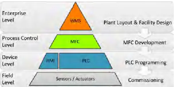
[image:24.595.153.457.565.717.2]For different control levels, the execution, examination and verification of control programs are executed individually. In present up-to-date material handling systems, there are different control levels of control components as shown in Figure 2.1 interacting with each other (Seidel et al, 2012). The lack of a common test bench leads to test the material flow controller (MFC) and programmable logic controller (PLC) programs individually. A test which combines equipment and control apparatuses can only be done on location and at a very late phase during the project duration. The outcomes of this method are conflicts between the planned behavior and the executed behavior. As result, the implementation of the system will be late due to programming faults lead to increase financial and prestige dangers for customer and contractor.
Figure 2.1: Control levels and corresponding project stages of material handling systems(Seidel et