Int. J. Electrochem. Sci., 7 (2012) 10562 - 10569
International Journal of
ELECTROCHEMICAL
SCIENCE
www.electrochemsci.org
A Simple Method of Making a Li-air Battery with Longevity
Xigui Zhang*,Li Hua, Endong Yang, Zhongxun An, Jingkun Chen, Xiaolin Chen, Xiaowei Chao, Jiafei Yu, Mingxia Wu, Xiaoli Miao
Shanghai Aowei Technology Development Co., Ltd, Shanghai 201203, China *E-mail: [email protected]
Received: 6 July 2012 / Accepted: 26 September 2012 / Published: 1 November 2012
In this paper, a simple and feasible method of making a coin-type Li-air battery (about 20mm in diameter and 28mm in height) was proposed. A special separator having function of air breathing and moisture prevention was adopted to act as a cover to let air breathe and prevent moisture invasion as well in cathode side. At the same time, a lithium ion conductive membrane was used between a Celgard membrane and a thin lithium foil to stop oxygen infiltrate into anode side. Compared with the prior art, electrochemical performance testing results showed that the cell had both better power performance and longer service life.
Keywords: Li-air battery; Air-breathing cathode; Lithium erosion; high power; longevity
1. INTRODUCTION
However, from the results reported by the previous researchers and the practical usage point of view, we notice that some key technical hinders still are required to overcome. For example, many researchers are using lithium super-ionic conductors (LISICON, LIPON or LAPT) to act as separator in lithium air batteries [6-8]. Nevertheless, these lithium ion conductors have obvious shortcomings such as chemical instability when contact with lithium metal, expensive and not-easy for fabrications. Another technical problem is moisture in air invades slowly into battery inside, erode lithium metal and degrade the battery’s electrochemical performances. The third problem is much lower kinetics reaction of the lithium air battery (the current density of the cell is commonly below 0.1mA/cm2based on calculating unit surface of the electrodes of the cell). Based on the above drawbacks, some researchers developed a different cell structure, that is Li |organic electrolyte| Li-ion conductor| inorganic electrolyte | air. Obviously, the cell’s structure is quite complex and at the same time, no feasible Li-ion conductor with both function of having li-ion conductance and impede water invading into lithium metal side is not available. So, for the practical application considerations, a new method is needed to fabricate a high power and longevity lithium air battery.
In this paper, a simple and feasible method of making a coin-type Li-air battery was proposed. A special separator having function of air breathing and moisture prevention was adopted to act as a cover to let air breathe and prevent moisture invasion in cathode side. Compared with the prior art, electrochemical performance tests showed that the cell had both better power performance and longer service life.
2. EXPERIMENTAL
2.1. Fabrication of the air-breathing electrode
30mg of Pt-Ru/C catalyst (60wt% metal content in 1:1 atom ratio, purchased from E-tek Inc.), 15mg of PTFE emulsion (60wt%, 3F company) and 0.25g NafionTM dispersion reagent(5wt% of Nafion, purchased from Dupont Company) were well mixed in DI water/isopropanol (1:1 in volume) by enough ultrasonic agitation to form a sticky slurry. Then the slurry was sputtering onto a home-made water proof carbon paper with a thickness of about 0.4mm and dried for about 4h at 100℃ to remove the organic and water substances(Fig.1a). As prepared air electrode was die-cut into circular disc with active area of about 2cm2.
2.2. Preparation of the Li-ion electrolyte
2.3. Assembly of the coin-type cell
The coin cell kit of 2025 was chosen to act as house of the Li-air battery. The positive pan of the cell kit has 45×Ф0.5mm laser drilled small holes to let air in and ensure even distribution(Fig.1b). Assist by the weight load, the circular air electrode disc was firstly bonded to inside of the positive pan of the cell kit by using special glue and dried for overnight to ensure good seal and bond between the air electrode and the pan (Fig.1c). 0.5mm lithium foil was also die-cut into circular disc with active area of about 2.5cm2. Circular polypropylene membrane of Celgard 2400 with diameter of 1.9mm was used as a separator. The Li-air battery coin cell was built by placing a piece of separator onto the air electrode bonded with the positive pan, adding an appropriate amount of as prepared electrolyte onto the separator, placing a Li-ion conductive membrane between a Celgard membrane and a thin lithium foil to stop oxygen infiltrate into aonde side, then placing a piece of as prepared lithium disc and a nickel foam disc (1.4mm in diameter), and finally placing the cover with a PP gasket. The whole assembly was crimped in argon filled MRraun glove box with moisture and oxygen content<1ppm. The crimped force of the crimper was about 10MPa. A circular rubber-like disc with a thickness of about 1.0mm was used to cover the pan facing outside. A special rubber like separator of 2cm in diameter having function of air breathing and moisture prevention in central circular area of about 1cm was adopted to act as a cover to let air breathe and prevent moisture invasion in cathode side (Fig.1d). The rubber like cover was tightly seal with outside of the positive pan by adhesive substance.
Figure1. Fabrication of a coin-type lithium-air cell
a. carbon paper with catalytic layer
c. air electrode bonded positive pan
b. positive pan with small holes
2.4. Physical-Chemical and electrochemical performances testing of the coil-type cell
X-ray diffraction (XRD) measurement of the catalytic positive electrode material (Pt/C) was carried out on a Rigaku D/max2200PC diffractometer, and the surface morphology of the electrodes was observed using a Hitachi S-4700 Scanning Electron.Microscope(SEM). Specific area and micro and mesopores were measured by Micrometrics ASAP2020. Electrochemical performance testing was carried out through an Arbin SCTs instrument. The cell’s impedance measurements were carried out using a Solartron SI1287 electrochemical analyzer combined with a Solartron 1255B frequency interface and a Zview 3.0 software. The instrument used in potentiostatic mode with amplitude 5mV over a frequency range from 0.001 Hz to 10000Hz, covered with 10 points per decade.
[image:4.596.92.508.303.497.2]3. RESULTS AND DISCUSSION
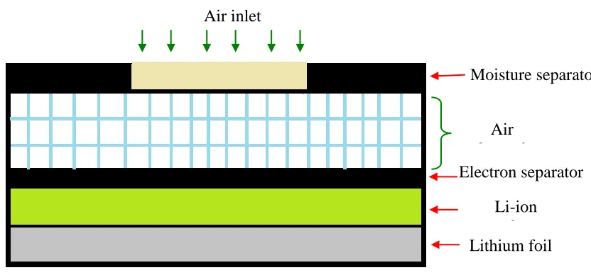
Figure 2. the schematic structure diagram of the coin-type lithium-air battery
Fig.2 shows the schematic structure diagram of the coin-type lithium-air battery we made. Its cell reaction and electrochemical potentials of Li-air battery are commonly written as 4LiO2 2Li2O E 2.91V
0
.However, from oxygen consumption measurements and experimental data analysis[5,13,14], the equation 4LiO2 2Li2O2 E 3.10V
0
was found also occur. However, the open circuit voltage (OCV) are affected by the material purity, electrode fabrication method and cell’s assembly technique, so different researching groups tends to give different OCV values[3,8]. Our cell’s OCV is 3.05V and close toE0 3.10V, which means the initial reaction main product is Li2O2.
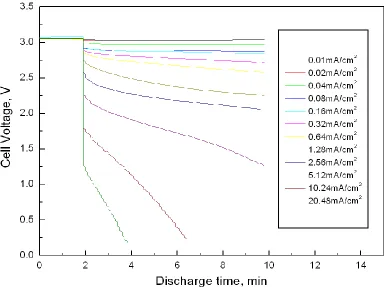
Fig.3 gives out the cell's discharge performance at different current densities. As we can see, when the cell is discharged at the smaller current densities(from 0.01-0.64mA/cm2), the discharge curves exhibits obvious higher discharge plateau, which means the cell's reaction kinetics is
Lithium foil Li-ion conductor Electron separator
Air electrode
[image:5.596.95.482.249.536.2]
controlled only by electrochemical resistance (Rct). When discharge current increases, the discharge curves tend to incline, which means the cell’s reaction kinetics is controlled both by electrochemical resistance (Rct) and Ohmic resistance(R). This phenomenon is some different from the common battery’s reaction kinetics. Likely, as the discharge current continually increases, the cell’s curves become much sharper, which mean diffusion resistance gradually controls the cell’s electrochemical reaction step at larger current. Its over voltage reaches about 1.8V at discharge current density of 20.48mA/cm2. However, compared with the prior literature, our cell showed the largest current density discharge ability, which may root from good structure design, pore size distribution(not shown) and material’s phases(not shown).
Figure 3. The cell's discharge performance at different current densities
Figure 4. The cell’s discharge power performance under constant discharge current
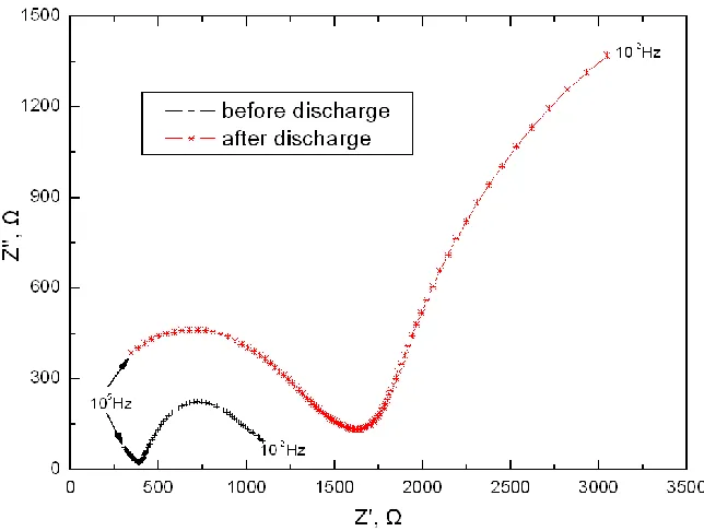
Figure 5. Nyquist plots for the cell before and after discharge
In fact, we can calculate the whole instant resistance of the cell at the beginning of constant current discharge. For example, when the cell is discharged at constant current of 40.96mA,
[image:6.596.125.447.406.649.2]
I2Rdrop=72.1mW, so total R=72.1*10-3/(40.96*10-3)2=43.0Ω. When the cell’s discharge current decreases, total R of reaction impedance reduces accordingly.
Fig.5 shows Nyquist plots for the cell before and after discharge. It can be seen that shape of the curves are quite different from that of the conventional Lithium Ion Batteries(LIBs), Nickel Hydride batteries(NHs) and also the previous reported literatures regarding to Lithium air batteries(LABs)[6,8]. The curves are some complex. We believe that structural design, properties of active materials, and assembling method could contribute lots to this characteristic but need further investigation for details. Nevertheless, we can see that after full discharge, impedance of the cell became much bigger compared with that of cell before discharge. It is evident that reaction product of Li2O2(or Li2O) clogged the pores of diffusion layer in cathode side and took up the active sites, which many researchers has pointed out[4,9-12].
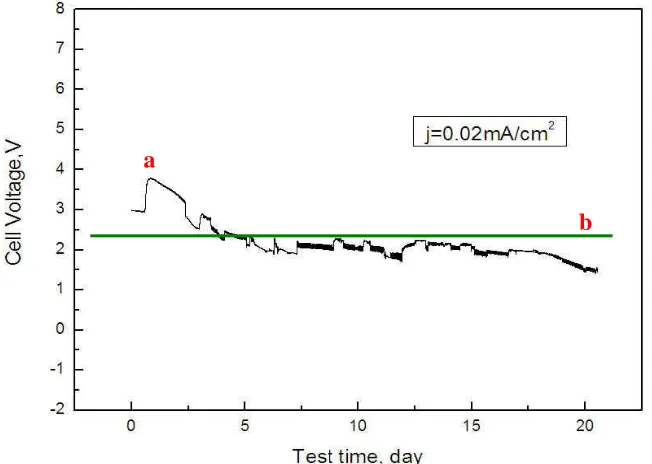
[image:7.596.131.457.394.626.2]Life performance of the coin type lithium-air battery at constant discharge current of 40µA is shown in Fig.6. It can be seen that the cell’s life performance is quite good. After 20days continuously discharge, the cell’s voltage still remains above 1.50V. Fluctuation occurred at initial stage (see point a) and then the cell’s voltage curve became some smooth. The cell’s voltage kept quite stable from the third day to the eighteenth day. Then the cell’s voltage began to drop at faster ratio. This is probably lack of enough active sites arising from the products’ clog and the cell tends to terminate quickly.
Figure 6. Life performance of the cell at constant discharge current of 40µA
4. CONCLUSIONS
A coin-type Li-air battery was fabricated by a simple and feasible method. More than 20days of continuous discharge at t 0.02mA/cm2 was obtained under the ambient conditions. In addition, the cell
a
exhibited better power performance compared with the prior published literature. Long term electrochemical test showed that the cell’s voltage violently fluctuation at the initial stage and stabilized from the third day to the eighteenth day whose further detailed investigation mechanism is still needed. The result of the electrochemical impedance experiment showed that the plot was quite complex and quite different from that of the traditional Lithium-air battery. However, after full discharge, impedance of the cell became much bigger compared with that of cell before discharge. It is evident that reaction product of Li2O2(or Li2O) clogged the pores of diffusion layer in cathode side and took up the active sites, which many researchers has pointed out.
ACKNOWLEDGEMENT
The authors gratefully acknowledge the partial financial support from the Chinese Hi-tech Research and Development Program (863) under Grant No. 2011AA11A233, Programs of Science and Technology Commission of Shanghai Municipality under Grants of No.11DZ2291600, 11dz1210501, 11DZ2210600 and 11dz1204400. The authors would also like to acknowledge the following members for their contributions during the preparation of this paper: Mr. Jianhong Xu, Mr. Liangliang Yan, Mr. Tingli Huang, Mr. Jiapo Heng, and Ms. Fangfang Chen. Special thanks to Mr. Qiang Wang, Mrs Guangcui Peng, Guangyan Pan and Youmei Zhu for their great labors in cell’s component and assembling work and Mr. Tao Wang from Institute of Shanghai Space Power Sources for his help in providing positive electrode materials and valuable discussions and comments.
References
1. O. Crowther, D. Keeny, D. M. Moureau, B. Meyer, M. Salomon, M. Hendrickson. J. Power Sources, 202(2012) 347.
2. J. Li, N. Wang, Y. Zhao, Y. Ding, L. Guan. Electrochem. Commun., 13(2011) 698. 3. H. Cheng, K. Scott. Appl. Catal. B-Environ., 108(2011) 140.
4. Y. Wang, H. Zhou. J. Power Sources, 195(2010) 358. 5. K.M. Abraham, Z. Jiang. J Electrochem. Soc., 143(1996) 1.
6. Y. Shimonishi, T. Zhang, P. Johnson, N. Imanishi, A. Hirano, Y. Takeda, O. Yamamoto, N. Sammes. J. Power Sources, 195(2010) 6187.
7. A.G. Ritchie. J. Power Sources, 96(2001) 1.
8. N. Imanishi, S. Hasegawa, T. Zhang, A. Hirano, Y. Takeda, O. Yamamoto. J. Power Sources, 185(2008) 1392.
9. X. Yang, P. He, Y. Xia. Electrochem. Commun., 11(2009) 1127.
10. A. Débart, J. Bao, G. Armstrong, P. G. Bruce. J. Power Sources, 174(2007) 1177. 11. P. Fragnaud, D.M. Schleich. Sensor Actuat A-Phys., 51(1995) 21.
12. D. Zhang, R. Li, T. Huang, A. Yu. J. Power Sources, 195(2010) 1202.
13. W. Xu, J. Xiao, J. Zhang, Deyu Wang, J.G. Zhang. J. Electrochem. Soc., 156(2009) A773. 14. S. S. Zhang, D. Foster, J. Read. J. Power Sources, 195(2010) 1235.